


Create successful ePaper yourself
Turn your PDF publications into a flip-book with our unique Google optimized e-Paper software.
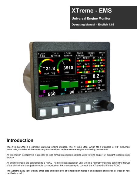
<strong>XTreme</strong> - <strong>EMS</strong>Universal Engine MonitorOperating <strong>Manual</strong> – English 1.02IntroductionThe <strong>XTreme</strong>-<strong>EMS</strong> is a compact universal engine monitor. The <strong>XTreme</strong>-<strong>EMS</strong>, which fits a standard 3 1/8” instrumentpanel hole, contains all the necessary functionality to replace several engine monitoring instruments.All information is displayed in an easy to read format on a high resolution wide viewing angle 4.3” sunlight readable colordisplay.All engine sensors are connected to a RDAC (Remote data acquisition unit) which is normally mounted behind the firewallof the aircraft and then just a simple communication link is necessary to connect the <strong>XTreme</strong>-<strong>EMS</strong> to the RDAC.The <strong>XTreme</strong>-<strong>EMS</strong> light weight, small size and high level of functionality makes it an excellent choice for all types of noncertifiedaircraft.
<strong>XTreme</strong>-<strong>EMS</strong> Operating <strong>Manual</strong> Page 21 FeaturesEngine Monitoring:• 1x Engine RPM display• 1x Rotor RPM display (<strong>MGL</strong> <strong>Avionics</strong> RDAC-XF / MAP required)• 1x Manifold pressure display (<strong>MGL</strong> <strong>Avionics</strong> RDAC-XF MAP required)• 1x Oil pressure display• 1x Oil temperature display• 2x Auxiliary analog channel displays (Pressure,Temperature or Current)• 12 Channel EGT/CHT display• 2x Fuel Flow displays (Dual fuel flow requires the RDAC-XF / MAP)• 2x Fuel Level displays• 1x Fuel pressure display (<strong>MGL</strong> <strong>Avionics</strong> RDAC-XF / MAP required)• 1x Current input (<strong>MGL</strong> <strong>Avionics</strong> RDAC-XF / MAP required)• Special Rotax 912/914 engine monitor mode utilizing the standard built in Rotax NTC CHT probes• Special Rotax 912IS mode (<strong>MGL</strong> <strong>Avionics</strong> RDAC CAN required)• Programmable maintenance timer for scheduled routine engine maintenance• User settable Hobbs meter (password protected)• Fuel range / endurance calculated from GPS ground speed. (Requires external RS232 GPS receiver)• Supply Voltage display• OAT (Outside Air Temperature) display• Engine leaning feature• Stopwatch timer• Automatic / <strong>Manual</strong> flight timer• RTC (Real Time Clock)• CO Monitor. (CO Guardian CO detector required)• The engine display screen is automatically configured to optimize screen space depending on whatengine parameters has been selectedHardware:• Powerful 32 bit ARM processor• 4.3” high resolution 480x272, sunlight readable, wide viewing angle, 600 cd/m2 TFT LCD display• LED backlight (brightness can be adjusted for low light flying conditions)• Fits standard 3 1/8” aircraft instrument panel hole• SD Card interface for data recording, user splash screens, checklists, graphic information pages, firmwareupgrades etc• 1x RS232 communication port (Either for a CO Monitor or an external GPS receiver)• 1x <strong>MGL</strong> <strong>Avionics</strong> Airtalk communication port• 1x <strong>MGL</strong> <strong>Avionics</strong> RDAC optical communications port• 1x CAN communication port (RDAC-XF / MAP interface)• Rotary control plus 5 independent buttons for easy menu navigation and user input• External alarm switch output for an external indicator lamp etc• Support for an external GPS receiver• Support for an external CO Monitor device• Built in RTC (Real Time Clock)• Wide input supply voltage range of 8 to 30V DC• Built in voltage reversal and over voltage protection for harsh electrical environments• Light weight design
<strong>XTreme</strong>-<strong>EMS</strong> Operating <strong>Manual</strong> Page 3General:• Records maximum and minimum values of most displayed values• Built in black box recorder – records all engine data and GPS data to SD card. Data can be exported toGoogle Earth, Microsoft Excel, etc.• Includes a 1000 entry automatic flight log (Records start date&time, flight time, pilot number, Hobbs timeand maintenance time)• User configurable start up (Splash) screen• Unlimited configurable checklists• Unlimited configurable graphic information displays• Automatic or manual local magnetic variation• Dual menu system for quick item selection and user setups• Sunrise/Sunset calculator• Firmware upgrades via SD Card• 1 year limited warranty
<strong>XTreme</strong>-<strong>EMS</strong> Operating <strong>Manual</strong> Page 53 Display ScreensPress the left or right most soft keys to cycle through the display screens.<strong>EMS</strong> DISPLAYGPS DISPLAY (External GPS receiver required)CHECKLIST/INFO DISPLAY
<strong>XTreme</strong>-<strong>EMS</strong> Operating <strong>Manual</strong> Page 63.1 <strong>EMS</strong> Display3.1.1 Information barFLIGHT:The flight time is automatically reset to zero when a new flight is started (manual or automatic flight detection). The “:” willflash when a flight is active. The flight timer can be started in the quick select menu (<strong>Manual</strong> flight mode).LOCAL:Local time normally includes an offset from Zulu time. The time offset can be setup in the “TIMERS SETUP” menu.TIMER:The Timer can be configured in the quick select menu.HOBBS:The <strong>XTreme</strong>-<strong>EMS</strong> contains a password protected Hobbs timer. The Hobbs time can be set to the current known enginetime in the “TIMERS SETUP” menu. The Hobbs timer will only increment when the RPM is greater then the “HOBBSMINIMUM RPM”.MAINT (Maintenance Timer):This timer is set in engine hours and it will count down to zero when the engine RPM is greater then the “HOBBSMINIMUM RPM” value as set in the “TIMERS SETUP”. A good use for this function is to set the hours until your nextspark plug change or engine inspection.The purpose of this function is to assist you in determining remaining hours until maintenance will be required. It is notintended as a replacement for the aircraft's maintenance log. It is therefore important that the aircraft's maintenance logbe maintained in the normal manner. You should further use your own discretion in performing maintenance earlier thanindicated should any aircraft performance problems arise.
<strong>XTreme</strong>-<strong>EMS</strong> Operating <strong>Manual</strong> Page 7A maximum of 999 hours can be entered as a maintenance interval. Areminder message will appear on startup when zero hours areremaining. The reminder message will automatically disappear after 10seconds or if the pilot presses any key. Engine running time for thepurpose of the maintenance timer is defined as the run time where the engine RPM is greater than the “HOBBSMINIMUM RPM” value as set in the “TIMERS SETUP”.CO (PPM):This value is the carbon monoxide PPM value from the CO Monitor Detector (CO Guardian detector required).3.1.2 RPM / Rotor / MAP display sectionThe RPM/Rotor/MAP section will maximize the space according to which parameter RPM/Rotor/MAP is enabled. TheRPM,Rotor and MAP parameters can be configured in the “<strong>EMS</strong> SETUP” menu.RPM,Rotor and MAP enabled.RPM and MAP enabled.RPM only enabledMAP only enabled3.1.3 Volts, OAT, Oil Temperature/Pressure, Current and Auxiliary Analog sectionThis section displays the supply voltage, OAT, oil temperature, oil pressure, aswell as the 2 auxiliary analog channels. The oil temperature/pressure as well asthe 2 auxiliary analog channels can be configured in the “<strong>EMS</strong> SETUP” menu.
<strong>XTreme</strong>-<strong>EMS</strong> Operating <strong>Manual</strong> Page 83.1.4 Fuel display sectionThe <strong>XTreme</strong>-<strong>EMS</strong> supports dual fuel flow, dual fuel levels and a single fuel pressure. The fuel section will automaticallytry and maximize the display area according to the fuel parameters selected. The fuel parameters can be configured inthe “FUEL SETUP” menu.3.1.4.1 Single fuel flow and calculated tank level (single tank)Single fuel flow and fuel level sender (single tank)Differential fuel flow and calculated tank level (single tank)Differential fuel flow and fuel level sender (single tank)Summed fuel flow and calculated tank level (single tank)Summed fuel flow and fuel level sender (single tank)3.1.4.2 Dual fuel flow and calculated tank levels (dual tank)Dual fuel flow and dual fuel level senders (dual tank)3.1.4.3 Single fuel flow and dual fuel level senders (dual tank)Single fuel flow, single fuel level sender, single calculated tankDifferential fuel flow and dual fuel level senders (dual tank)Differential flow, single fuel level sender, single calculated tankSummed fuel flow and dual fuel level senders (dual tank)Summed fuel flow, single fuel level sender, single calculated tank
<strong>XTreme</strong>-<strong>EMS</strong> Operating <strong>Manual</strong> Page 93.1.4.4 Single/Differential/Summed fuel flow, single fuel level sender, single calculated tankThese modes are nice for multiple fuel tanks whereby one or more tanks are difficult to insert level senders in. Potentialproblems such as those listed below can easily be diagnosed by doing side by side comparisons between a calculatedand physical tank.• Leaks in the fuel system• Uneven drain of interconnected tanks• Malfunction of the level sender• Malfunction of the flow sender3.1.4.5 Single fuel flow only indicatorThis mode is displayed if either fuel flow 1 or fuel flow 2 is selected and no fuel level senders are selected.3.1.4.6 Dual fuel flow indicatorThis mode is displayed if both fuel flow 1 and fuel flow 2 is selected and the fuel mode is selected for dual flow. Both fuellevel senders are disabled.3.1.4.7 Single tank level indicatorThis mode is displayed if either fuel level 1 or fuel level 2 is selected. Both fuel flow senders are disabled.3.1.4.8 Dual tank level indicatorThis mode is displayed if both fuel level 1 and fuel level 2 is selected. Both fuel flow senders are disabled.
<strong>XTreme</strong>-<strong>EMS</strong> Operating <strong>Manual</strong> Page 103.1.4.9 Differential/Summed fuel flowThis mode is displayed if both fuel flow 1 and fuel flow 2 is selected and the fuel mode is selected for either differentialor summed.3.1.4.10 Calculated Fuel TanksCalculated fuel tanks will have the text “CALC” in the fuel bar to indicate that the fuel level is calculated from fuel flow andthat it is not a physical measure of the fuel tank.3.1.4.11 Fuel PressureThe fuel pressure bar will be displayed when the fuel pressure has been enabled in the menu system. The below pictureillustrates a single physical fuel tank, with a single flow and fuel pressure enabled.3.1.4.12 Speed, Range and GPS Fix StatusThe speed value will change color depending on the source of the information:White: The <strong>XTreme</strong>-<strong>EMS</strong> is using the cruising speed for the range calculationMagenta: The <strong>XTreme</strong>-<strong>EMS</strong> is using the GPS ground speed for the range calculationCyan: The <strong>XTreme</strong>-<strong>EMS</strong> is using the airtalk airspeed for the range calculation
<strong>XTreme</strong>-<strong>EMS</strong> Operating <strong>Manual</strong> Page 113.1.5 EGT/CHT display sectionThe <strong>XTreme</strong> supports up to 12 thermocouples for EGTs/CHTs. The EGT/CHT section will automatically try and maximizethe display area according to the number of EGTs/CHTs selected. The EGT/CHT parameters can be configured in the“EGT SETUP” and “CHT SETUP” menu.The EGT/CHT number will highlight to the indicated the temperature value if “HIGHEST” is selected. The EGT highlightcolor is magenta, and the CHT color is cyan.High AlarmMaximum temperaturereached indicatorHigh CautionEGT group indicatorTemperature unitIndicates highest value if“HIGHEST” is selected orthe highlighted bar valueif “SCANNING” is selectedCHT group indicator
<strong>XTreme</strong>-<strong>EMS</strong> Operating <strong>Manual</strong> Page 123.2 <strong>EMS</strong> Quick Select Menu SystemPress the rotary control when the <strong>EMS</strong> screen is displayed to access the <strong>EMS</strong> quick selectmenu.START FLIGHT:Select this option to manually start/stop a flight. This menu option is only shown if the <strong>XTreme</strong>-<strong>EMS</strong> is setup to select themanual flight option under the “FLIGHT LOG” setup menu. The ':' will flash to indicate that a valid flight is in progress.FUEL REFILL:Select this menu option to refill a calculated fuel tank.Press the “FULL” soft key for a quick fill to the fullreading in the tank setup menu. Press the “EXIT”soft key when done.CRUISE SPEED:Select this menu option to enter your average cruisingspeed. If there is no GPS fix or no airtalk airspeed dataavailable then the Xtreme-<strong>EMS</strong> will use the averagecruising speed to calculate fuel range. It is advisable toenter your average cruising speed irrespective if you areusing an external GPS receiver or external airtalkairspeed device. If the GPS signal is lost during flightthen the Xtreme-<strong>EMS</strong> automatically defaults to thisvalue.
<strong>XTreme</strong>-<strong>EMS</strong> Operating <strong>Manual</strong> Page 13LEAN MODE:EGT information is also very useful for fuel mixture control. As the fuel mixture is leaned, so the exhaust gasses gethotter. This rise in temperature is a sign of increased combustion efficiency as the optimum mixture setting is approached.If the leaning progresses past a certain point however, the temperature will begin to drop. This temperature drop is theresult of reduced energy output from the diminished fuel flow. The best operating mixture for aircraft engines is in thevicinity of this peak EGT reading. The <strong>XTreme</strong>-<strong>EMS</strong> has a special Leaning mode, which easily identifies the peak EGTcondition allowing you to adjust your fuel mixture for best performance. Fuel mixture should be adjusted once you havedecided on a suitable cruise power setting (typically 70%). Once leaning mode has been enabled, the "LEAN MODE"label is displayed at the bottom left of the <strong>EMS</strong> display to clearly differentiate it from the normal operating mode. As thefuel mixture is slowly leaned past the point at which the temperature begins to drop (by more than 10°C/15°F), theabsolute EGT temperatures will change to show the EGT reading relative to this peak. The sequential order as eachcylinder peaks is also shown as numeric text under the cylinder. Leaning mode can be canceled by pressing the soft keyto “OFF” or by changing the display screen.EGT Temperaturewhile leaningEGT Reading relativeto first peaked cylinderLean mode indictor2nd cylinder to peak1st cylinder to peakCRUISE MODE:Once cruise mode has been enabled, the "CRUISE MODE" label is displayed atthe bottom of the <strong>EMS</strong> display to clearly differentiate it from the normal operatingmode. All EGT and CHT readings are immediately sampled as referencetemperatures for the cruise. The display then shows EGT and CHT valuesrelative to this reference temperature. Cruise mode can be canceled by pressingthe soft key to “OFF”.FUEL TOTALS:Select this menu option to display the fuel totals. Pressthe “RESET” soft key to reset the totalisers to zero.Press the “EXIT” soft key when done.
<strong>XTreme</strong>-<strong>EMS</strong> Operating <strong>Manual</strong> Page 14TIMER:Select this menu option to configure the timer. Use therotary control to adjust the timers reset value. Press the“UP/DOWN” soft key to select whether the timer mustcount up or down, the “START/STOP” soft key tostart or stop the timer and the “ON/OFF” soft key toenable or disable the timer.MIN/MAX:Select this menu option to display the maximum andminimum captured values. Press the “RESET” soft keyto reset the min/max values to the current values.BACKLIGHT:Select this menu option to adjust the backlight brightness level. This may be desirableduring low light flying conditions. Use the rotary control to adjust the brightness level.MENU:Select this menu option to enter the main menu system.
<strong>XTreme</strong>-<strong>EMS</strong> Operating <strong>Manual</strong> Page 153.3 GPS Display (External RS232 GPS receiver required)The GPS page show the GPS information in an easy to read format. Sunrise/sunset times as well as the magneticvariation is shown.3.4 GPS Quick Select Menu SystemPress the rotary control when the GPS screen is shown to access the GPS quick select menu.BACKLIGHT:Select this menu option to adjust the backlight brightness level. This may be desirableduring low light flying conditions. Use the rotary control to adjust the brightness level.MENU:Select this menu option to enter the main menu system.
<strong>XTreme</strong>-<strong>EMS</strong> Operating <strong>Manual</strong> Page 163.5 Information/Checklist DisplayThe Information / Checklist page shows checklists and graphic information pages which are loadable from the SD card.The last checklist or graphic information page is automatically loaded as startup.3.5.1 Graphic information pagesThe graphic information page allows you to display any type of image on the <strong>XTreme</strong>s high resolution graphics display.Creating your own graphic information pagesYou will need:·A bitmap picture of your choice (*.BMP, 480x272 pixel resolution)·The Enigma BMP to MIF converter tool (can be downloaded free of charge from http://www.mglavionics.co.za or can befound on the <strong>XTreme</strong>-<strong>EMS</strong> distribution SD card).The Enigma BMP to MIF program is used to convert images in Windows BMP format to Enigma MIF format. You can usethis program to make your own startup screen (Splash screen) and graphic information pages. The color depth is limitedto Enigmas 256 colors.Run the Enigma BMP image to MIF format converter program.Load an image file (and remember the location), select the resolution as width (480) and height (272) and press theprocess button. The new MIF image will be located in the same directory as the source (.BMP) file. Copy the created file(.MIF extension) to the Infopage directory on the SD card.The graphic information file can then be loaded by pressing the rotarycontrol and selecting “INFO PAGES”. A window containing all the fileswith the .MIF extension is shown. Select the desired information page.The number of information pages that can be stored and displayeddepends on the size of the SD card.
<strong>XTreme</strong>-<strong>EMS</strong> Operating <strong>Manual</strong> Page 173.5.2 ChecklistsA checklist file is simply a text file created in a word processing program and saved with a .ECL extension. The name ofthe file does not matter but we suggest calling it something familiar so you can easily identify it. The length of each textline must not be more then 60 characters and must be terminated with an Enter (CR). The line will automatically betruncated at the end of the right hand side of the screen. Each checklist file must not be more then 30 lines.Copy the created file (.ECL extension) to the checklst directory on theSD card when you are complete. The checklist file can be loaded bypressing the rotary control and selecting “CHECKLISTS”. A windowcontaining all the files with the .ECL extension will shown. Select thechecklist you require. The number of checklists that can be stored anddisplayed depends on the size of the SD card.3.6 Information/Checklist Quick Select Menu SystemPress the rotary control when the Info/Checklist screen is shown to access the Info/checklistquick select menu.INFO PAGES:This menu option selects a graphic information page to display. A window will open displaying all the files with the .MIFextension in the Infopage directory on the SD card. Press the rotary control over the file you wish to load as a graphicinformation page.CHECKLISTS:This menu option selects a checklist to display. A window will open displaying all the files with the .XCL extension in theChecklst directory on the SD card. Press the rotary control over the file you wish to load as a checklist.BACKLIGHT:Select this menu option to adjust the backlight brightness level. This may be desirableduring low light flying conditions. Use the rotary control to adjust the brightness level.MENU:Select this menu option to enter the main menu system.
<strong>XTreme</strong>-<strong>EMS</strong> Operating <strong>Manual</strong> Page 184 Main Menu SystemTo access the main menu system, press the rotary control knob, scroll down to the “MENU”option and press the rotary control knob again. Use the rotary control to navigate the menusystem.4.1 Menu Sub-BarUse the menu sub-bar for quick menu navigation. Select the soft key directly under the text to activate the softkeyfunction. Some soft keys have a x1, x10, x100, x1000 assigned to them. This allows for faster incrementing anddecrementing of the menu settings.
<strong>XTreme</strong>-<strong>EMS</strong> Operating <strong>Manual</strong> Page 194.2 Flight LogNOTE: The Flight log is stored in RAM until a valid flight has been completed. If the power is turned off to the<strong>XTreme</strong>-<strong>EMS</strong> before the flight has ended then the flight information will be lost.EXPORT FLIGHT LOG TO SD CARD (.CSV FILE):Use this function to export the current flight logs stored in the <strong>XTreme</strong>-<strong>EMS</strong> to a SD card. The exported filename is calledXTFLIGHT.CSV. The exported flight log is exported in a CSV (Comma Separated Variable) file format and can beimported into programs such as Microsoft Excel and Open Office.VIEW FLIGHT LOG:This allows the pilot to view the last 1000 recorded flights.ERASE FLIGHT LOG:Use this function to erase the current flight log stored in the <strong>XTreme</strong>-<strong>EMS</strong>.PILOT NUMBER:Select a pilot number under which the next flights will be logged. Every flight entry in the flight log has a pilot numberassociated to it.FLIGHT DETECT:Select if you want the flight log to automatically “AUTOMATIC” start or if you want to manually “MANUAL” start and stopit.
<strong>XTreme</strong>-<strong>EMS</strong> Operating <strong>Manual</strong> Page 20The <strong>XTreme</strong> uses the following algorithm to determine if a flight is in progress (“AUTOMATIC” mode): If the ground speedis greater than the preset “FLIGHT DETECT MIN GROUND SPEED” value or the RPM is greater than the preset“FLIGHT DETECT MINIMUM RPM” value for a duration of 60 seconds or more, a flight is started with a logbook entry.The flight ends if ground speed or RPM falls below the preset value for 30 seconds.The above algorithm ensures that touch-and-goes will not result in the end of a flight and a logbook entry.FLIGHT DETECT MINIMUM RPM: (Automatic mode only)Enter the minimum RPM threshold that will start a new flight log entry.FLIGHT DETECT MINIMUM GROUND SPEED: (Automatic mode only, External GPS Required)Enter the minimum ground speed threshold that will start a new flight log entry.
<strong>XTreme</strong>-<strong>EMS</strong> Operating <strong>Manual</strong> Page 214.3 <strong>EMS</strong> Setup
<strong>XTreme</strong>-<strong>EMS</strong> Operating <strong>Manual</strong> Page 224.3.1 RPM SetupRPM DISPLAY:Select if you want the RPM to be displayed in “RPM” or “PERCENT” .If you do not want any RPM information then set thisparameter to "OFF". If the rotor RPM is set to "RPM" or "PERECENT" then the engine RPM display will automatically beenabled.RPM 100% DISPLAY:Select the maximum value that you want the RPM to correlate to 100%.RPM DISPLAY MAX:Select the maximum RPM that you want the RPM dial to show. This can give you increased display resolution.RPM DISPLAY MIN:Select the minimum RPM that you want the RPM dial to show. This can give you increased display resolution.HIGH ALARM:This enables or disables the RPM high alarm.HIGH ALARM:Enter the RPM threshold for when the high alarm must be activated. Any RPM value above this value will activate thealarm.HIGH CAUTION:Enter the RPM value for the high caution. This is the lower value of the upper yellow band.LOW CAUTION:Enter the RPM value for the low caution. This is the upper value of the lower yellow band.LOW ALARM:This enables or disables the RPM low alarm.LOW ALARM:Enter the RPM threshold for when the low alarm must be activated. Any RPM value below this value will activate thealarm.
<strong>XTreme</strong>-<strong>EMS</strong> Operating <strong>Manual</strong> Page 23PULSES/REV:Enter the number of pulses per RPM. For engines with an uneven number of cylinders like three cylinder four strokeengines you can enter values containing fractions (usually 1.5 in this example). Most four stroke engines would generateone pulse for every two revolutions per cylinder. A four cylinder automotive four stroke engine would thus generate 2pulses per revolution. A typical Rotax DCDI two stroke engine would generate 6 pulses per revolution. The well knownRotax 912/914 engine generates one pulse per revolution.RPM RESOLUTION:Select the step size between successive RPM values eg. if the RPM value is 4003 RPM and the “RPM RESOLUTION” is5 then the actual value shown is 4005 RPM.
<strong>XTreme</strong>-<strong>EMS</strong> Operating <strong>Manual</strong> Page 244.3.2 Rotor SetupROTOR DISPLAY:Select if you want the rotor RPM to be displayed in “RPM” or “PERCENT” .If you do not want any rotor RPM informationthen set this parameter to off. If the rotor RPM is set to "RPM" or "PERECENT" then the engine RPM display willautomatically be enabled.ROTOR 100% DISPLAY:Select the maximum value that you want the rotor RPM to correlate to 100%.HIGH ALARM:This enables or disables the Rotor RPM high alarm.HIGH ALARM:Enter the Rotor RPM threshold for when the high alarm must be activated. Any Rotor RPM value above this value willactivate the alarm.HIGH CAUTION:Enter the Rotor RPM value for the high caution. This is the lower value of the upper yellow band.LOW CAUTION:Enter the Rotor RPM value for the low caution. This is the upper value of the lower yellow band.LOW ALARM:This enables or disables the Rotor low alarm.LOW ALARM:Enter the Rotor RPM threshold for when the low alarm must be activated. Any Rotor RPM value below this value willactivate the alarm.PULSES/REV:Enter the number of pulses per rotor RPM.ROTOR RESOLUTION:Select the step size between successive Rotor RPM values eg. if the Rotor RPM value is 403 RPM and the “ROTORRESOLUTION” is 5 then the actual value shown is 405 RPM.
<strong>XTreme</strong>-<strong>EMS</strong> Operating <strong>Manual</strong> Page 254.3.3 EGT/CHT SetupEGT/CHT CHANNELS:Select the number of EGT or CHT channels you want to use. Choices are from 1 to 12. The temperature display willconfigure itself to make best possible use of the available display size. Please note that the minimum number of EGT &CHT channels that can be displayed is 1 and the maximum number of EGT and CHT channels that can be displayed is12.EGT/CHT DISPLAY MAX:Select the maximum temperature that you want the EGT/CHT bargraph to show. This can give you increased displayresolution.EGT/CHT DISPLAY MIN:Select the minimum temperature that you want the EGT/CHT bargraph to show. This can give you increased displayresolution.HIGH ALARM:This enables or disables the EGT/CHT high alarm.HIGH ALARM:Enter the temperature threshold for when the high alarm must be activated. Any temperature above this value will activatethe alarm.HIGH CAUTION:Enter the temperature value for the high caution.
<strong>XTreme</strong>-<strong>EMS</strong> Operating <strong>Manual</strong> Page 26PROBE:Select if you are using a K-type, J-type or E-type thermocouple probe for the EGT/CHT group. All probes supplied by<strong>MGL</strong> <strong>Avionics</strong> are K-Type. J-types are sometimes used with American made CHT probes. All EGT probes are K-type. E-type probes are seldom used.TEMPERATURE UNIT:Select whether you want the EGT/CHT temperature to be displayed in degrees Celsius (ºC) or degrees Fahrenheit (ºF).MODE:A selection between “HIGHEST” or “SCANNING” can be selected. If “HIGHEST“ is selected then the current highestthermocouple temperature is displayed. If “SCANNING” is selected then the unit will cycle through each thermocouple atthe time specified in “SCAN TIME”.SCAN TIME:Specify the time that each of the channels must be displayed for. This menu option is only shown if “SCANNING” isselected for the display mode.4.3.3.1 Special Rotax 912/914 probe modeIn this mode the RDAC AUX 3 and AUX 4 analog input channels become the Rotax CHT channel 1 and CHT channel 2respectively. All CHT setups must still be done under the “CHT SETUP” menu. The sender selection for the “AUX 3” and“AUX 4” must be set for “OFF”. A probe type of “NTC” must be selected for the probe setting in the “CHT SETUP” menu.The reason for using the NTC inputs is that the sensors Rotax use are standard NTC temperature probes and not of athermocouple type.
<strong>XTreme</strong>-<strong>EMS</strong> Operating <strong>Manual</strong> Page 274.3.4 Fuel SetupUNIT:Select your desired units for distance and fuel quantity. The following options are available:L/sm: Liters and statute milesG/sm: U.S. Gallons and statute milesL/nm: Liters and nautical milesG/nm: U.S. Gallons and nautical milesL/km: Liters and kilometerG/km: U.S. Gallons and kilometersSPEED:Select which speed will be used for fuel range/endurance based calulations. You can select beteween "AIRTALK-AIRSPEED" which can be transmitted from an external airspeed indicator such as the <strong>MGL</strong> <strong>Avionics</strong> ASI-1/3 or "GPS-GROUND SPEED". If a 2D or 3D GPS is not obtained and "GPS-GROUND SPEED" is selected then the <strong>XTreme</strong>-<strong>EMS</strong>will default to use the cruising speed for the fuel range/endurance calculations.FLOW 1/2:This enables or disables the Flow 1/2 display on the EFIS and MFD displays.KFACTOR 1/2:The K-Factor is the number of pulses generated by the fuel flow sender for one liter of fuel. The dual range fuel flowsender supplied by <strong>MGL</strong> <strong>Avionics</strong> has a K-Factor of 7000 in the low flow mode (jet installed) and 1330 for the high flowmode (no jet installed). The Flowscan 201A-6 has a K-Factor of 8454. You can use the K-Factor to calibrate your fuel flowsender. See the RDAC manual for more details on how to calibrate and install the fuel flow sender.MODE:Select if you want to measure fuel flow using a fuel flow sender or by using fuel injectors.FLOW MODE:If both fuel flow senders are selected then select if they are operating on individual fuel tanks (dual) or if they areoperating in a supply/return type fuel system (differential).TANK 1/2 SETUP:Select this menu item to setup the fuel level for fuel tank 1/2. See below for more details.
<strong>XTreme</strong>-<strong>EMS</strong> Operating <strong>Manual</strong> Page 28Fuel level setup. (Only tank 1 setup is shown, follow the same steps for tank 2 setup)TANK 1/2:Select if the fuel tank has a physical fuel level sender connected to it or if the Xtreme must use a calculation based virtualfuel tank. If you do not want any fuel level information then set this parameter to off.TANK SIZE:Enter the size of the fuel tank in your system. It is recommended to choose a size that is slightly less than the actual sizeso you can compensate for sender inaccuracies and give you a measure of reserve fuel.LOW ALARM:This enables or disables the fuel level low alarm.LOW ALARM:Enter your desired minimum fuel value that you would like to trigger the fuel low alarm.LOW CAUTION:Enter the fuel level value for the low fuel caution.CALIBRATE TANK:The fuel level sender needs to be calibrated before it can be used with this system. The calibration allows the system tolearn the shape of your tank as well as any errors your fuel level sender or installation has.Regardless of your use of a fuel flow sender, you can install a fuel level sender into your fuel tank. These level sendersare inexpensive and are available as after market replacement fittings from a car spares outlet. We recommend thesenders available from VDO.Be aware that some makes of cheap level senders can prove troublesome, as the lever arms tend to be sticky. Thisprevents the floats from floating on the surface of the fuel at all times. As a consequence, this will lead to incorrect fuellevel indication.
<strong>XTreme</strong>-<strong>EMS</strong> Operating <strong>Manual</strong> Page 29Adjusting calibration points automaticallySelect “SENDER” for the “MODE” menu item. Once you have installed a fuel level sender into your tank, make sure thefloat can travel all the way from empty to full position without hindrance of any kind. The calibration procedure should becarried out with your aircraft in flight attitude. This means you need to lift the tail if you have a tail-dragger or lift the nosewheel if you have a weightshift trike.Calibration procedureStart the calibration procedure with an empty tank.Add five liters of fuel (our reserve quantity) using a suitable measure. Make sure the measure is suitablyaccurate. This is now the “level sender reading at 0 Lt” position. Move the highlight to this position and wait untilthe sender reading has stabilized (You will see the sender reading at the top line). This could take up to a minuteso have patience.ENSURE THAT THE FLOAT IS NOT SUBMERGED AND IS FLOATING ON TOP OF THE FUEL LEVEL.Should this number not react to changes of your level sender position, then you have a problem. Please checkyour wiring according to the installation section of this manual. You should expect the number to change in theregion of at least 20 to 60 counts per calibration position. If the number does not change with fuel level or onlychanges a very small amount – check your installation. Something is not right!• If you see the number changing then everything is well. Once it has stabilized and the highlight is on the 0 Lposition, press the rotary control to transfer the reading from the sender to the calibration point.• Now you are ready for the next step. Add the required amount of fuel to get to the next level (In our case 9 Lt –this is 20% tank capacity). Once done, wait for the reading to stabilize and press the rotary control again after youhave moved the highlight to the “9 L” position.• Proceed in a similar manner until you have reached the last calibration position at 100% tank capacity.You are done!To finish your calibration, exit the calibration function by moving the highlight over the “- - -PREVIOUS MENU - --” menu item and press the rotary control.The instrument uses the 6 calibration points to work out a correction curve that takes into account the tolerances of yourfuel level sender and the shape of your fuel tank. This results in an incredibly accurate and usable fuel level display thatfar exceeds that available from ordinary dial type gauges.
<strong>XTreme</strong>-<strong>EMS</strong> Operating <strong>Manual</strong> Page 30Adjusting calibration points manuallyYou may want to set individual calibration points manually. For example you may find that your fuel level is overreading at a specific fuel level. Correcting the tank level reading for this area can be simply done by adjusting thecalibration point. You can do this by moving the float level with your hands to the desired position and then performing thecalibration as outlined above, or you can use the manual option.Select “MANUAL” for the “MODE” menu item. Then highlight the point you want to change manually and press the rotarycontrol. Use the rotary control to adjust the value. Press the rotary control when done.Note: The calibration positions may be edited by using the rotary control. This allows you, in theory, to copy calibrationsettings from one instrument to another. We however recommend that you do go though the calibration procedure even ifthe two aircraft are identical in all respects. Tolerances do exist and the calibration cancels these out. Accurate fuel leveldisplays are a vital safety factor for an aircraft and a very useful feature for peace of mind during cross county flights.Notes on Slope errorSender value is a value determined by the <strong>XTreme</strong>. Itis used to calculate fuel level, fuel enduranceestimate and current range estimate. The fuel tanksetup sender value can either increase in value asfuel is added or decrease in value if fuel is added.This is dependent on the type of fuel level senderused. However should the second reading be largerthan the first reading all readings will have to belarger than the previous readings. Likewise shouldthe second reading be smaller than the first readingall readings will have to be smaller than theprevious reading.If this is not the case the wording "SLOPE ERROR" will be displayed. This could happen when fuel was removed insteadof added between steps, no fuel was added between steps or when the fuel level sender was moved in the wrongdirection e.g. moving the fuel level sender manually when it is not inserted in to the fuel tank. Determine the cause of theerror if you should get a slope error message. If you do not know the cause of your error it is best to start from scratch. Itshould be remembered that accuracy in the fuel tank calibration is extremely important to enable your <strong>XTreme</strong> to displaythe correct data.TANK FILTER:Select the damping factor for the fuel level. A selection of "NONE", "LOW", "MED" or "HIGH" can be made.
<strong>XTreme</strong>-<strong>EMS</strong> Operating <strong>Manual</strong> Page 31FUEL PRESSURE SETUP: (<strong>MGL</strong> <strong>Avionics</strong> RDAC-XF / MAP Required)Select this menu item to setup the fuel pressure input.FUEL PRESSURE DISPLAY:This enables or disables the fuel pressure display on the <strong>EMS</strong> display screenTYPE:Select if you are using a resistive, 4-20mA or 0-5V output pressure sender.If the “RESISTIVE” pressure sender is selectedSENDER:Select what type of resistive pressure sender you are using. Select “VDO” for VDO / resistive senders, “USER” for acustom sender.MODEL:Select which VDO pressure sender you are using. A selection between a VDO 2, 5 or 10 Bar can be selected.If the “0-5V” pressure sender is selectedSENDER:Select the type of 0-5V sender used. Select “UMA” for UMA senders of “USER” for a custom 0-5V sender.MODEL:For UMA senders select the UMA model number.If the “4-20mA” pressure sender is selectedSENDER:Select the type of 4-20mA sender used. Select “ROTAX” for Rotax 912/914 4-20mA sender or “USER” for a custom 4-20mA sender.PRESSURE @ 4mA:Enter the pressure specified at 4mA output.
<strong>XTreme</strong>-<strong>EMS</strong> Operating <strong>Manual</strong> Page 32PRESSURE @ 20mA:Enter the pressure specified at 20mA output.If the “USER" pressure sender is selectedCALIBRATE SENDER:If the sender type is set to “USER”, then use this menu option to calibrate your pressure sender. See section 4.4.9 formore information.Menu options for all sender typesPRESSURE UNIT:Select whether you want to display the pressure in Bar, PSI or PSI(0.1). The PSI(0.1) is for low range pressure senderse.g. UMA 7PSI.DISPLAY MAX:Select the maximum pressure that you want the oil pressure bargraph to show. This can give you increased displayresolution.DISPLAY MIN:Select the minimum pressure that you want the oil pressure bargraph to . This can give you increased display resolution.HIGH ALARM:This enables or disables the pressure high alarm.HIGH ALARM:Enter the pressure threshold for when the high alarm must be activated. Any pressure above this value will activate thealarm.HIGH CAUTION:Enter the pressure value for the high caution. This is the lower value of the upper yellow band.LOW CAUTION:Enter the pressure value for the low caution. This is the upper value of the lower yellow band.LOW ALARM:This enables or disables the pressure low alarm.LOW ALARM:Enter the pressure threshold for when the low alarm must be activated. Any pressure below this value will activate thealarm.
<strong>XTreme</strong>-<strong>EMS</strong> Operating <strong>Manual</strong> Page 334.3.5 Manifold Setup (<strong>MGL</strong> <strong>Avionics</strong> RDAC-XF MAP required)MAP DISPLAY:This enables or disables the manifold pressure display on the <strong>EMS</strong> displays screensMAP UNIT:Select if you want the manifold pressure displayed in mB (millibars) or “Hg (inches of mercury).MAP DISPLAY MAX:Select the maximum pressure that you want the manifold bargraph in the <strong>EMS</strong> displays to show. This can give youincreased display resolution.MAP DISPLAY MIN:Select the minimum pressure that you want the manifold bargraph in the <strong>EMS</strong> display to show. This can give youincreased display resolution.HIGH ALARM:This enables or disables the manifold pressure high alarm.HIGH ALARM:Enter the pressure threshold for when the high alarm must be activated. Any pressure above this value will activate thealarm.HIGH CAUTION:Enter the pressure value for the high caution. This is the lower value of the upper yellow band.LOW CAUTION:Enter the pressure value for the low caution. This is the upper value of the lower yellow band.LOW ALARM:This enables or disables the manifold pressure low alarm.LOW ALARM:Enter the pressure threshold for when the low alarm must be activated. Any pressure below this value will activate thealarm.
<strong>XTreme</strong>-<strong>EMS</strong> Operating <strong>Manual</strong> Page 34FILTER:This function can be used to select the signal filter time constant. Selections are "NONE", “FAST” or “SLOW”. Thisselection influences the rate at which your manifold pressure can change its reading.MAP CALIBRATION FACTOR:The sender in the RDAC is shipped uncalibrated. To calibrate the manifold pressure, compare and adjust the calibrationfactor until the manifold reading is the same as the pressure value in brackets. The pressure value in brackets is thebarometer reading built into the Xtreme. The manifold pressure can only be calibrated in mB.
<strong>XTreme</strong>-<strong>EMS</strong> Operating <strong>Manual</strong> Page 354.3.6 Oil Temperature SetupOIL TEMPERATURE DISPLAY:This enables or disables the oil temperature display on the <strong>EMS</strong> displays screensSENDER:Select what type of sender you are using. Select “VDO” for a VDO resistive sender, “WESTACH” for Westach thermistortype senders, “<strong>MGL</strong>” for a <strong>MGL</strong> NTC resistive temperature sender, “LM335” for a <strong>MGL</strong> precision temperature sender or“USER” for a custom sender. The <strong>XTreme</strong> has a built in linearization curve for a standard 50ºC to 150ºC VDO resistivesender, Westach senders and the <strong>MGL</strong> NTC resistive sender.If the sender type is set to “USER"CALIBRATE SENDER:If the sender type is set to “USER”, then use this menu option to calibrate your temperature sender. See section 4.4.9 formore information.If the sender type is set to “LM335"LM335:If the sender type is set to LM335, then use this menu option to calibrate your LM335 precision temperature sender. Ifrecalibration is required then adjust the value using the rotary control until the temperature matches the reference ambienttemperature. Please note that the LM335 can only be calibrated in degrees Celsius irrespective if the <strong>XTreme</strong> is setup todisplay temperature in Fahrenheit.Menu options for all sender typesTEMPERATURE UNIT:Select whether you want the temperature to be displayed in degrees Celsius (ºC) or in degrees Fahrenheit (ºF).DISPLAY MAX:Select the maximum temperature that you want the oil temperature bargraph to show. This can give you increaseddisplay resolution.
<strong>XTreme</strong>-<strong>EMS</strong> Operating <strong>Manual</strong> Page 36DISPLAY MIN:Select the minimum temperature that you want the oil temperature bargraph to show. This can give you increased displayresolution.HIGH ALARM:This enables or disables the temperature high alarm.HIGH ALARM:Enter the temperature threshold for when the high alarm must be activated. Any temperature above this value will activatethe alarm.HIGH CAUTION:Enter the temperature value for the high caution. This is the lower value of the upper yellow band.LOW CAUTION:Enter the temperature value for the low caution. This is the upper value of the lower yellow band.LOW ALARM:This enables or disables the oil temperature low alarm.LOW ALARM:Enter the temperature threshold for when the low alarm must be activated. Any temperature below this value will activatethe alarm.
<strong>XTreme</strong>-<strong>EMS</strong> Operating <strong>Manual</strong> Page 374.3.7 Oil Pressure SetupOIL PRESSURE DISPLAY:This enables or disables the oil pressure display on the <strong>EMS</strong> displays screensTYPE:Select if you are using a resistive, 4-20mA or 0-5V output pressure sender.If the “RESISTIVE” pressure sender is selectedSENDER:Select what type of resistive pressure sender you are using. Select “VDO” for VDO / resistive senders, “USER” for acustom sender.MODEL:Select which VDO pressure sender you are using. A selection between a VDO 2, 5 or 10 Bar can be selected.If the “0-5V” pressure sender is selectedSENDER:Select the type of 0-5V sender used. Select “UMA” for UMA senders of “USER” for a custom 0-5V sender.MODEL:For UMA senders select the UMA model number.If the “4-20mA” pressure sender is selectedSENDER:Select the type of 4-20mA sender used. Select “ROTAX” for Rotax 912/914 4-20mA sender or “USER” for a custom 4-20mA sender.PRESSURE @ 4mA:Enter the pressure specified at 4mA output.
<strong>XTreme</strong>-<strong>EMS</strong> Operating <strong>Manual</strong> Page 38PRESSURE @ 20mA:Enter the pressure specified at 20mA output.If the “USER" pressure sender is selectedCALIBRATE SENDER:If the sender type is set to “USER”, then use this menu option to calibrate your pressure sender. See section 4.4.9 formore information.Menu options for all sender typesPRESSURE UNIT:Select whether you want to display the pressure in Bar, PSI or PSI(0.1). The PSI(0.1) is for low range pressure senderse.g. UMA 7PSI.DISPLAY MAX:Select the maximum pressure that you want the oil pressure bargraph to show. This can give you increased displayresolution.DISPLAY MIN:Select the minimum pressure that you want the oil pressure bargraph to . This can give you increased display resolution.LOW ALARM:This enables or disables the pressure low alarm.LOW ALARM:Enter the pressure threshold for when the low alarm must be activated. Any pressure below this value will activate thealarm.LOW CAUTION:Enter the pressure value for the low caution. This is the upper value of the lower yellow band.HIGH CAUTION:Enter the pressure value for the high caution. This is the lower value of the upper yellow band.HIGH ALARM:This enables or disables the pressure high alarm.HIGH ALARM:Enter the pressure threshold for when the high alarm must be activated. Any pressure above this value will activate thealarm.
<strong>XTreme</strong>-<strong>EMS</strong> Operating <strong>Manual</strong> Page 394.3.8 Auxiliary analog 1/3, 2/4 SetupThe analog AUX 1/3,2/4 channel on the RDAC are general purpose channels that can be used for pressure, temperatureor current. The AUX 3 and 4 pertains to the RDAC-XF / MAP and AUX 1 and 3 to all the other RDACs.FUNCTION:Select the function for the analog channel. Options are “PRESSURE”, “TEMPERATURE”, “CURRENT” or “OFF”.If the “PRESSURE” function is selected:TYPE:Select if you are using a resistive, 4-20mA or 0-5V output pressure sender.If the “RESISTIVE” pressure sender is selectedSENDER:Select what type of resistive pressure sender you are using. Select “VDO” for VDO / resistive senders, “USER” for acustom sender.MODEL:Select which VDO pressure sender you are using. A selection between a VDO 2, 5 or 10 Bar can be selected.If the “0-5V” pressure sender is selectedSENDER:Select the type of 0-5V sender used. Select “UMA” for UMA senders of “USER” for a custom 0-5V sender.
<strong>XTreme</strong>-<strong>EMS</strong> Operating <strong>Manual</strong> Page 40MODEL:For UMA senders select the UMA model number.If the “0-20mA” pressure sender is selectedSENDER:Select the type of 4-20mA sender used. Select “ROTAX” for Rotax 912/914 4-20mA sender or “USER” for a custom 4-20mA sender.PRESSURE @ 4mA:Enter the pressure specified at 4mA output.PRESSURE @ 20mA:Enter the pressure specified at 20mA output.If the “USER" pressure sender is selectedSENDER:Select the type of 4-20mA sender used. Select “ROTAX” for Rotax 912/914 4-20mA sender or “USER” for a custom 4-20mA sender.CALIBRATE SENDER:If the sender type is set to “USER”, then use this menu option to calibrate your pressure sender. See section 4.4.9 formore information.Menu options for all sender typesLABEL:Choose one of a selection of labels to suit your pressure input so you can identify it easily.PRESSURE UNIT:Select whether you want to display the pressure in Bar, PSI or PSI(0.1). The PSI(0.1) is for low range pressure senderse.g. UMA 7PSI.DISPLAY MAX:Select the maximum pressure that you want the bargraph to show. This can give you increased display resolution.DISPLAY MIN:Select the minimum pressure that you want the bargraph to show. This can give you increased display resolution.HIGH ALARM:This enables or disables the pressure high alarm.HIGH ALARM:Enter the pressure threshold for when the high alarm must be activated. Any pressure above this value will activate thealarm.HIGH CAUTION:Enter the pressure value for the high caution. This is the lower value of the upper yellow band.LOW CAUTION:Enter the pressure value for the low caution. This is the upper value of the lower yellow band.
<strong>XTreme</strong>-<strong>EMS</strong> Operating <strong>Manual</strong> Page 41LOW ALARM:This enables or disables the pressure low alarm.LOW ALARM:Enter the pressure threshold for when the low alarm must be activated. Any pressure below this value will activate thealarm.If the “TEMPERATURE” function is selected:SENDER:Select what type of sender you are using. Select “VDO” for a VDO resistive sender, “WESTACH” for Westach thermistortype senders, “<strong>MGL</strong>” for a <strong>MGL</strong> NTC resistive temperature sender, “LM335” for a <strong>MGL</strong> precision temperature sender or“USER” for a custom sender. The <strong>XTreme</strong> has a built in linearization curve for a standard 50ºC to 150ºC VDO resistivesender, Westach senders and the <strong>MGL</strong> NTC resistive sender.If the sender type is set to “USER"CALIBRATE SENDER:If the sender type is set to “USER”, then use this menu option to calibrate your pressure sender. See section 4.4.9 formore information.If the sender type is set to “LM335"LM335:If the sender type is set to LM335, then use this menu option to calibrate your LM335 precision temperature sender. Ifrecalibration is required then adjust the value using the rotary control until the temperature matches the reference ambienttemperature. Please note that the LM335 can only be calibrated in degrees Celsius irrespective if the <strong>XTreme</strong> is setup todisplay temperature in Fahrenheit.Menu options for all sender typesLABEL:Choose one of a selection of labels to suit your temperature input so you can identify it easily.TEMPERATURE UNIT:Select whether you want the temperature to be displayed in degrees Celcius (ºC) or in degrees Fahrenheit (ºF).
<strong>XTreme</strong>-<strong>EMS</strong> Operating <strong>Manual</strong> Page 42DISPLAY MAX:Select the maximum temperature that you want the bargraph to show. This can give you increased display resolution.DISPLAY MIN:Select the minimum temperature that you want the bargraph to show. This can give you increased display resolution.HIGH ALARM:This enables or disables the temperature high alarm.HIGH ALARM:Enter the temperature threshold for when the high alarm must be activated. Any temperature above this value will activatethe alarm.HIGH CAUTION:Enter the temperature value for the high caution. This is the lower value of the upper yellow band.LOW CAUTION:Enter the temperature value for the low caution. This is the upper value of the lower yellow band.LOW ALARM:This enables or disables the temperature low alarm.LOW ALARM:Enter the temperature threshold for when the low alarm must be activated. Any temperature below this value will activatethe alarm.4.3.9 Calibrating the user defined pressure and Temperature Senders1. Enter the number of points that you want tocalibrate.2. Enter the display reading that you want toshow when the sender is at that actual displayreading.3. Enter the ADC (analog to digital converter)reading that corresponds to this display reading.The ADC reading is shown at the bottom of thedisplay if you are applying the actualstimulus from the temperature or pressuresender. You can also manually enter this valueif the ADC value is known or pre-calculated.4. Continue entering display and ADC valuesuntil all the points have been entered.5. Verify the above calibration by checking thetemperature/pressure display versus the actualapplied sender stimulus.
<strong>XTreme</strong>-<strong>EMS</strong> Operating <strong>Manual</strong> Page 43If the “CURRENT” function is selected: (<strong>MGL</strong> <strong>Avionics</strong> Current Sensor required)DISPLAY MAX:Select the maximum current that you want the bargraph to show. This can give you increased display resolution.DISPLAY MIN:Select the minimum current that you want the bargraph to show. This can give you increased display resolution.HIGH ALARM:This enables or disables the current high alarm.HIGH ALARM:Enter the current threshold for when the high alarm must be activated. Any current above this value will activate thealarm.HIGH CAUTION:Enter the current value for the high caution. This is the lower value of the upper yellow band.LOW CAUTION:Enter the current value for the low caution. This is the upper value of the lower yellow band.LOW ALARM:This enables or disables the current low alarm.LOW ALARM:Enter the current threshold for when the low alarm must be activated. Any current below this value will activate the alarm.ZERO CURRENT SENSOR:Select this function to indicate to the <strong>XTreme</strong> that zero current is flowing through the <strong>MGL</strong> current monitor. This is bestdone with the <strong>MGL</strong> current monitor disconnected from the main current suppling conductor.CURRENT SPAN CALIBRATION:Enter the maximum value that your <strong>MGL</strong> current monitor can measure. This will depend on the distance and the methodthat is used to attach the <strong>MGL</strong> current monitor to the main current supplying conductor. It will be best if a multimeter canbe inserted in series with the current supplying conductor and the span calibration adjusted until the <strong>XTreme</strong> matches thatof the multimeter. Please see the <strong>MGL</strong> current monitor document for more information.
<strong>XTreme</strong>-<strong>EMS</strong> Operating <strong>Manual</strong> Page 444.3.10 Volts SetupVOLTS DISPLAY MAX:Select the maximum value that you want the volts bargraph in the <strong>EMS</strong> display to show. This can give you increaseddisplay resolution.VOLTS DISPLAY MIN:Select the minimum value that you want the volts bargraph in the <strong>EMS</strong> display to show. This can give you increaseddisplay resolution.HIGH ALARM:This enables or disables the volts high alarm.HIGH ALARM:Enter the voltage threshold for when the high alarm must be activated. Any voltage above this value will activate thealarm.HIGH CAUTION:Enter the voltage for the high caution. This is the lower value of the upper yellow band.LOW CAUTION:Enter the voltage for the low caution. This is the upper value of the lower yellow band.LOW ALARM:This enables or disables the volts low alarm.LOW ALARM:Enter the voltage threshold for when the low alarm must be activated. Any voltage below this value will activate the alarm.VOLTS CALIBRATION FACTOR:Measure the battery voltage with a multimeter and then adjust this value to match that of the multimeters volts reading.
<strong>XTreme</strong>-<strong>EMS</strong> Operating <strong>Manual</strong> Page 454.3.11 Current Setup (<strong>MGL</strong> <strong>Avionics</strong> RDAC-XF / MAP required)This menu options is only used if you have a <strong>MGL</strong> <strong>Avionics</strong> RDAC-XF / MAP RDAC and <strong>MGL</strong><strong>Avionics</strong> current sensor.CURRENT DISPLAY:Select to enable or disable the current bar graph.DISPLAY MAX:Select the maximum current that you want the bargraph to show. This can give you increased display resolution.DISPLAY MIN:Select the minimum current that you want the bargraph to show. This can give you increased display resolution.HIGH ALARM:This enables or disables the current high alarm.HIGH ALARM:Enter the current threshold for when the high alarm must be activated. Any current above this value will activate thealarm.HIGH CAUTION:Enter the current value for the high caution. This is the lower value of the upper yellow band.LOW CAUTION:Enter the current value for the low caution. This is the upper value of the lower yellow band.LOW ALARM:This enables or disables the current low alarm.LOW ALARM:Enter the current threshold for when the low alarm must be activated. Any current below this value will activate the alarm.ZERO CURRENT SENSOR:Select this function to indicate to the <strong>XTreme</strong> that zero current is flowing through the <strong>MGL</strong> current monitor. This is bestdone with the <strong>MGL</strong> current monitor disconnected from the main current supplying conductor.
<strong>XTreme</strong>-<strong>EMS</strong> Operating <strong>Manual</strong> Page 46CURRENT SPAN CALIBRATION:Enter the maximum value that your <strong>MGL</strong> current monitor can measure. This will depend on the distance and the methodthat is used to attach the <strong>MGL</strong> current monitor to the main current suppling conductor. It will be best if a multimeter can beinserted in series with the current supplying conductor and the span calibration adjusted until the <strong>XTreme</strong> matches that ofthe multimeter. Please see the <strong>MGL</strong> current monitor document for more information.
<strong>XTreme</strong>-<strong>EMS</strong> Operating <strong>Manual</strong> Page 474.3.12 OAT SetupOAT TEMPERATURE UNIT:Select whether you want the OAT to be displayed in degrees Celsius (ºC) or in degrees Fahrenheit (ºF).OAT DISPLAY MAX:Select the maximum temperature that you want the OAT bargraph in the <strong>EMS</strong> display to show. This can give youincreased display resolution.OAT DISPLAY MIN:Select the minimum temperature that you want the OAT bargraph in the <strong>EMS</strong> display to show. This can give youincreased display resolution.HIGH ALARM:This enables or disables the OAT high alarm.HIGH ALARM:Enter the temperature threshold for when the high alarm must be activated. Any temperature above this value will activatethe alarm.LOW ALARM:This enables or disables the OAT low alarm.LOW ALARM:Enter the temperature threshold for when the low alarm must be activated. Any temperature below this value will activatethe alarm.OAT CALIBRATION FACTOR:During the factory calibration a factor has been determined and entered here that will give you an accurate OAT reading.If you find this value is incorrect then adjust the calibration factor until the <strong>XTreme</strong>s OAT matches that of a precisionthermometer. Calibration can only be done in Celcius (ºC).
<strong>XTreme</strong>-<strong>EMS</strong> Operating <strong>Manual</strong> Page 484.3.13 CO Monitor Carbon Monoxide SetupThe CO Monitor Carbon Monoxide menu option allows the pilot to enable the CO Guardians Carbon Monoxide detector.The <strong>XTreme</strong>-<strong>EMS</strong> will display the carbon monoxide value on the <strong>EMS</strong> display as well as enable the carbon monoxidewarning alarm. Please see the relevant CO Guardian detector manuals for more information.CO MONITOR:Select which CO Monitor you are using. Select “None” to disable the CO display.RESET CO GUARDIAN:This will reset the CO Guardian Carbon Monoxide detector, perform a self test and then will re-enable the CO GuardianCarbon Monoxide detector.
<strong>XTreme</strong>-<strong>EMS</strong> Operating <strong>Manual</strong> Page 494.3.14 ROTAX 912IS Setup (<strong>MGL</strong> <strong>Avionics</strong> RDAC CAN required)The Rotax ECU transmits various status messages. These can be observed in the Engine, Sensor and Device statusfields. Please see the 912IS installation and parameter settings in the installation section. When a <strong>MGL</strong> <strong>Avionics</strong> RDACCAN unit is connected then the Xtreme-<strong>EMS</strong> will automatically rename AUX1/3 to COOLANT TEMP.
<strong>XTreme</strong>-<strong>EMS</strong> Operating <strong>Manual</strong> Page 50
<strong>XTreme</strong>-<strong>EMS</strong> Operating <strong>Manual</strong> Page 514.4 GPS SetupGPS:Select “OFF” to disable the GPS information screen or select "EXTERNAL" if you have an external NMEA compatibleGPS connected to the <strong>XTreme</strong>-<strong>EMS</strong>.If an external GPS is used then it must output the following NMEA sentences•GGA - Global positioning system fix data•RMC – Recommended minimum specific GNSS data•GSA – GNSS DOP and active satellites•GSV – GNSS satellites in viewNMEA stands for the National Marine Electronics Association. For more information please visit www.nmea.org.GPS BAUD RATE:Select the baud rate to match the external GPS receiver you are using.POSITION FORMAT:Select the display format of the GPS latitude and longitude.ALTITUDE UNIT:Select the unit of the altitude display.COG:Select if you want the COG to be related to true or magnetic north.LOCAL VARIATION:Select “AUTO” to allow the <strong>XTreme</strong>-<strong>EMS</strong> to automatically calculate the local variation or “MANUAL” for manual localvariation input.AUTO LOCAL VARIATION:This item displays the calculated local magnetic variation. The <strong>XTreme</strong>-<strong>EMS</strong> will calculate the local variation every 10minutes if a valid 2D or 3D GPS fix is obtained.MANUAL LOCAL VARIATION:This item allows the pilot to manually enter his local variation.
<strong>XTreme</strong>-<strong>EMS</strong> Operating <strong>Manual</strong> Page 524.5 Timers SetupHOBBS MINIMUM RPM:Enter the RPM limit in which the Hobbs timer/Maintenance timer must start incrementing.SET HOBBS TIME:This function allows you to set the engine Hobbsmeter to any value. Typically, you would use thisfunction to set the Hobbs meter to the currentknown engine time. Use the rotary control tochange the value. Press the rotary control toaccept and exit the menu option. If the Hobbscode is set to another value beside zero, then thepilot will be prompted to enter the Hobbs accesscode before allowing him to change the Hobbs time.This feature is useful for charted and flying schoolplanes.CHANGE HOBBS CODE:This menu option allows you to change the Hobbs access code. You will first be prompted to enter the current codefollowed by entering in a new code followed by re-entering the new code. If the new code and the re-entered code is thesame, then the Hobbs access code will be changed. Default code is 0000.
<strong>XTreme</strong>-<strong>EMS</strong> Operating <strong>Manual</strong> Page 53SET MAINTENANCE TIMER:These timers allow you to keep track of enginemaintenance interval. Set the timer when you haveserviced your engine. A typical time might be 50hours. This function allows you to set an enginemaintenance timer. This timer is set in engine hoursand it will count down to zero when the engine RPMis greater then the “HOBBS MINIMUM RPM”. Agood use for this function is to set the hours untilyour next spark plug change or engine inspection.Use the rotary control to change the value.UTC OFFSET:Enter the UTC offset for your location. The UTC offset can be adjust in half an hour increments.RTC SOURCE:Select if you want the RTC UTC time to come from the GPS receiver or the internal RTC. Both real time clocks arepowered by an internal 3V lithium coin cell battery. The internal battery can be replaced by unscrewing the 5 screwsholding the back and front enclosures together as well as the 2 screws next to the D15 connector. Delicately slide out theelectronics and replace the battery. The battery is a CR2032 coin cell.SET UTC DATE & TIME:Use the rotary control to set the UTC date & time inthe internal RTC.
<strong>XTreme</strong>-<strong>EMS</strong> Operating <strong>Manual</strong> Page 544.6 Data Recording SetupThe <strong>XTreme</strong>-<strong>EMS</strong> has the ability to act as a black box recorder recording flight data directly onto an inserted SD card forlater playback and investigation using the <strong>MGL</strong> <strong>Avionics</strong> Black Box viewer program. See the Black box viewer documentsfor further information. The Black box viewer can also convert the data into other file formats such as:• KML: Keyhole Markup Language / Google Earth• CSV: Comma-Separated Variable• IGC: FAI Gliding commissionThe <strong>XTreme</strong>-<strong>EMS</strong> records the engine data as well as the GPS data (If an external GPS receiver is available) once persecond WHEN A VALID FLIGHT IS DETECTED (AUTOMATIC OR MANUAL FLIGHT DETECT MODE).CREATE RECORDING FILE ON SD CARD:Selecting this menu option will create a file on the SD card (If inserted and not write protected) called enigma.rec with afixed file size of 10MB. The reason behind the fixed file size of the recording file has to do with limited write cycles of theSD card and the instability of the MS-DOS file system. With a fixed file size, the <strong>XTreme</strong>-<strong>EMS</strong> never has to write to eitherthe directory structure or FAT tables of the SD card eliminating wear of the card or possible data corruption. Once therecording file has been filled, the recording continues at the start of the file again, overwriting the oldest data in the file.The file size is large enough to record 5-20 hours of data depending on what data is recorded.DATA RECORDING ON:Selecting “ON” will enable the data recording functionality.
<strong>XTreme</strong>-<strong>EMS</strong> Operating <strong>Manual</strong> Page 554.6.1 Examples of the exported flight data using CSV format and the KML format
<strong>XTreme</strong>-<strong>EMS</strong> Operating <strong>Manual</strong> Page 564.7 Miscellaneous SetupAIRCRAFT REGISTRATION:Enter your aircraft registration. A maximum of 8characters can be entered. The aircraft registration isdisplayed on the start up (Splash) screen.SAVE SETTINGS TO SD CARD:Select this option to save all the <strong>XTreme</strong>-<strong>EMS</strong> settings to the SD card. This is useful when setting up the instrument onthe PC simulator and then later transferring the settings on the instrument itself. A file called “XTREME.<strong>EMS</strong>” will becreated in the root directory of the SD card. This function is also used to save your settings during firmware upgrades.RECALL SETTINGS FROM SD CARD:Select this option to recall all the <strong>XTreme</strong>-<strong>EMS</strong> settings from the SD card. This is useful when setting up the instrumenton the PC simulator and then later transferring the settings to the instrument itself. The settings will be loaded from a filecalled “XTREME.<strong>EMS</strong>” in the root directory of the SD card. This function is also used to recall your settings after afirmware upgrade.RDAC PROTOCOL:This option is only valid if using the optical RDAC interface, ignore this option if using the CAN interface. If using theRDAC-XF or RDAC-XF MAP RDAC and using the optical interface then set this menu option to extended otherwise set itto normal. Please note that the RDAC-XF dip switches must be SET to A=ON and B=ON for the extended messages towork. Please see the installation section for more information.It is recommended to use the CAN interface if using the RDAC-XF or RDAC-XF MAP
<strong>XTreme</strong>-<strong>EMS</strong> Operating <strong>Manual</strong> Page 574.8 ADC ValuesThese values are mainly used for debugging purposes. Contact the <strong>MGL</strong> factory or your local dealer for more information.5 Startup (Splash) ScreenCreating your own Startup (Splash) Screen:You will need:·A bitmap picture of your choice (*.BMP, 480x272 pixel resolution)·The Enigma BMP to MIF converter tool (can be downloaded free of charge from http://www.mglavionics.co.za or can befound on the <strong>XTreme</strong> SD card).The Enigma BMP to MIF program is used to convert images in Windows BMP format to Enigma MIF format. You can usethis program to make your own startup screen (Splash screen) and graphic information display screens. The color depthis limited to Enigmas 256 colors.Run the Enigma BMP image to MIF format converter program.Load an image file (and remember the location), select the resolution as width(480) and height (272) and press theprocess button. The new MIF image will be located in the same directory as the source (BMP) file.If the original file was not named Splash.BMP, rename the new *.MIF file to Splash.MIF, and copy the Splash.MIF file intothe root directory of your SD card.The picture will be displayed when the unit is powered up.
<strong>XTreme</strong>-<strong>EMS</strong> Operating <strong>Manual</strong> Page 586 Loading factory default settingsPress and hold the left and right most soft keys simultaneously on power up to load default factory settings. The followingmessage will be displayed:7 Alarm conditionIf an alarm condition occurs the following will happen:• The item causing the alarm condition will flash on the screen• An alarm warning message will be displayed on the screen• An external alarm switch will closeThe alarm warning message and switch closure will remain until any button is pressed or until the condition(s) thatactivated the alarm no longer exist.The alarm output can be used to switch an external alarm indicator. The external alarm switch is an open collectortransistor switch to ground with a maximum rating of 0.5A DC. It is possible to wire the alarm contacts of severalStratomaster instruments in parallel should this be desired.To avoid false activation of the alarms, the alarm function is only active 10 seconds after the instrument has powered up.8 CleaningThe unit should not be cleaned with any abrasive substances. The screen is very sensitive to certain cleaning materialsand should only be cleaned using a clean, damp cloth.Warning: The <strong>XTreme</strong>-<strong>EMS</strong> is not waterproof. Serious damage could occur if the unit is exposedto water and/or spray jets.
<strong>XTreme</strong>-<strong>EMS</strong> Operating <strong>Manual</strong> Page 599 <strong>XTreme</strong>-<strong>EMS</strong> SpecificationsOperating Temperature Range -10ºC to 50ºC (14ºF to 122ºF)Storage Temperature Range -20ºC to 80ºC (-4ºF to 176ºF)Power Supply8 to 30Vdc SMPS (switch mode power supply)Built in 33V over voltage and reverse voltage protectionCurrent Consumption Approx. 130mA @ 13.8VPower Consumption Approx. 1.8W4.3” 480x272 pixel active matrix TFT LCDDisplay600 cd/m2Sunlight ReadableDisplay BacklightLEDFront panel user adjustableDimensionsFits standard 3 1/8” instrument holeSee section 12 for dimensional drawingsADC12 bits 100kspsBlack ABSEnclosureFront mountingRear of enclosure fits a standard 3 1/8” instrument holeWeightApprox. 250 grams (<strong>XTreme</strong>-<strong>EMS</strong> unit only)Alarm contact current ratingOpen collector transistor switch to groundMaximum rating 0.5A DCNon-volatile memory storage 100000 write cyclesWarm up time10 minutes
<strong>XTreme</strong>-<strong>EMS</strong> Operating <strong>Manual</strong> Page 6010 Installation10.1 <strong>XTreme</strong>-<strong>EMS</strong> General Connection DiagramThe use of an external 1A fuse is recommended. Connect the supply terminals to your aircraft’s power supply. The<strong>XTreme</strong>-<strong>EMS</strong> can be used on both 12V and 24V without the use of any pre-regulators. Ensure that the supply voltage willnot drop below 8V during operation as this may result in incorrect readings.Please see below for RDAC installation and usage.
<strong>XTreme</strong>-<strong>EMS</strong> Operating <strong>Manual</strong> Page 6110.2 <strong>XTreme</strong>-<strong>EMS</strong> DB15 Cable connectionsD15 MaleDB 15 Pin Color Function1 Red 8-30Vdc power2 White Alarm Output3,4,9,10 Black Ground5 NC RS232 Port 2 Transmit6 NC RS232 Port 2 Receive7 NC RS232 Port 1 Transmit8 NC RS232 Port 1 Receive11 Green OAT Probe12 NC CAN High13 NC CAN Low14 NC RDAC Signal15 NC AirtalkNC = Not ConnectedThe <strong>XTreme</strong>-<strong>EMS</strong> has a D15 Female connector. The connecting cable must have a D15 male connector attached to it.The communication interface from your RDAC must be connected to either to the CAN bus or to the RDAC signal. Seethe installation section below for more details on the 2 communications interfaces and the different RDAC units.
<strong>XTreme</strong>-<strong>EMS</strong> Operating <strong>Manual</strong> Page 6210.3 <strong>MGL</strong> <strong>Avionics</strong> RDAC VDThe RDAC model VD is an integrated, microprocessor controlled engine monitoring subsystem. It is intended forinstallation close to the engine, inside the engine compartment thereby eliminating the need for long probe and senderwires. If using the RDAC-VD then the RDAC protocol setting in the miscellaneous section must be set to normal.10.3.1 The RDAC VD provides the following functions:4 x EGT and/or CHT thermocouple inputs2 x analog inputs intended for NTC type temperature senders1 x oil temperature sender input (NTC or semiconductor types)1 x oil pressure sender (resistive types)2 x fuel level inputs (resistive types or active capacitive probes with low impedance voltage output from 0-2.5V)1 x fuel flow sender input, can also be used to measure injector opening times on fuel injected engines to derive indirectfuel flow measurement.1 x variable sensitivity RPM inputThe RDAC VD is intended for installation on all engines where up to four thermocouple senders are sufficient. For largerengines, please see the RDAC-XF and RDAC-XF MAP models. The RDAC VD is a good choice for engines such as mosttwo stroke engines,Rotax 912/914 engines and smaller two cylinder four stroke engines.10.3.2 RDAC VD Power supplyThe RDAC VD requires supply from a 12V DC source. Voltages such as found in typical 12V nicad or lead-acid batterybased installations are acceptable. The RDAC VD is designed to operate from 8VDC to 18VDC. Should your aircraft havea 24/28V system, you need to provide a 12V preregulator.In order to achieve maximum accuracy, it is important to route the power supply wiring correctly.It is important that the ground terminal connection is routed in as sort as possible manner to the engine block.The engine block must have a connection to the negative of the battery. Normally this connection is provided in the formof a heavy duty cable to allow for the considerable currents of an electric starter motor. Should your installation not haveelectric start, you will still need to provide this connection. Do not route the ground wire directly to the battery minus. This
<strong>XTreme</strong>-<strong>EMS</strong> Operating <strong>Manual</strong> Page 63can lead to false readings on some senders. The ground wire must be routed to the engine block. You must have aconnection from the engine block to the battery minus.The red wire must be connected to a +12V source.10.3.3 RDAC VD function indicatorThe RDAC VD has a red LED that will flash in an approximate 0.5-1 second interval if power has been supplied and theRDAC is functioning.Note: If you have not connected the ground terminal to the engine block and the engine block does not have a groundconnection to the battery minus then the LED will not flash and your RDAC will not operate.10.3.4 RDAC VD communications linkThe RDAC VD has a serial data communications link that is optically isolated, i.e. it has no electrical connection to theRDAC electronics itself. This prevents any form of electrical current flowing in this cable in case of an electrical wiring faultin your aircraft, in particular ground faults.There are three connections that are required to be connected:Braid – Connect to the <strong>XTreme</strong>-<strong>EMS</strong> ground (D15 Pin 3,4,9,10)Blue (Data line) – Connect to the blue wire of the Xtreme-<strong>EMS</strong> (D15 pin 14)Red – Connect to the <strong>XTreme</strong>-<strong>EMS</strong> +12V power (D15 Pin 1).Used to power a pull-up resistor on the blue wire andprovide the positive power connection to the RDAC
<strong>XTreme</strong>-<strong>EMS</strong> Operating <strong>Manual</strong> Page 6410.3.5 Installation of the RDAC VDThe RDAC VD must be installed with the following requirements met:a) The RDAC must not be exposed to direct engine vibrations. Never mount the RDAC on the engine itself. Mount theRDAC on on the aircraft's firewall or similar suitable structure.b) The RDAC must be installed so extreme heat from the engine cannot damage it.c) The RDAC must be mounted in a position where it is protected from any engine oils or other engine fluids includingwater.d) If required the RDAC should be mounted inside a protected enclosure if it is otherwise not possible to protect it fromenvironmental exposure such as rain.e) All wires to the baseboard must be secured such that it is not possible or any wire to be damaged due to chafing or thatany wire can loosen itself from its connection terminal.f) If the RDAC is operated in conditions that may lead to corrosion of exposed electrical metal parts, suitable protection isa mandatory requirement.g) The RDAC includes very good protection against voltage transients on the power supply. However, in cases wheresevere transients containing a large amount of energy are expected, additional, external protection may be required.h) All signal connections that terminate in any of the RDAC terminals must never be allowed to contain dangerous highvoltages such as can be created by ignition systems or inductive devices. In particular never route such cables alongsideHT ignition leads.
<strong>XTreme</strong>-<strong>EMS</strong> Operating <strong>Manual</strong> Page 6510.3.6 RDAC VD principle wiring diagramThe following diagram shows a basic connection sample for various sensors. The actual connection of sensors dependson your application and setup in the display unit (instrument). Normally, in cases of multiple EGT/CHT thermocouplesensors, EGT sensors start from TC channel 1 while the CHT channels follow.The starting channel for CHT channels depends on your instruments setup.CHT1/H2O is used for either a NTC type water temperature sender or the 1 st CHT probe of a Rotax 912/914 engine.CHT2/ICE/FP is used for the 2 nd CHT probe of a Rotax 912/914 engine.
<strong>XTreme</strong>-<strong>EMS</strong> Operating <strong>Manual</strong> Page 6610.3.7 RDAC VD thermocouple inputsTypical Thermocouple setup here Shown for four EGT probes. Please note that the probes are color coded. Yellow wiresmust connect to the “+” terminals and the red wires must connect to the “-“ terminals.Thermocouple inputs – detailsThe RDAC VD <strong>EMS</strong> provides for up to 4 thermocouple inputs for use with EGT and CHT probes. Both K as well as J typeprobes can be used. K types are used for EGT probes while most CHT probes are also K types. Some makes of CHTprobes are J type. Probe types are selected in the “EGT SETUP” and “CHT SETUP” menus of your <strong>XTreme</strong>-<strong>EMS</strong>.Important: Incorrect selection will lead to incorrect temperature display.The RDAC VD <strong>EMS</strong> will accept both grounded and isolated thermocouple probes. Your only consideration in case of themore common grounded configurations is that you need to ensure that the thermocouple mounting position (Exhaustflange, etc) is at the same electrical potential as the negative supply line of the RDAC VD (REF GND).RDAC VD thermocouple guidelinesThe thermocouple amplifier is a precision device providing full cold junction compensation and bow voltage correction. Inaddition the amplifier measures and corrects for its own errors. This results in very accurate measurements providing youinstall high quality probes. Here are some guidelines:EGT Probes: Select probes that are made from 316 stainless steel and that use glass-fiber insulated conductors. Tefloninsulated conductors as found in many cheap probes introduce errors as the insulation melts moving the measuring pointtowards the mounting bolt which transfers a lot of heat to the exhaust material. This results in under reading probes. Stayaway from probes that use simple plastic heat shrink sleeving – it does not last. Choose probes that use a generousamount of stainless steel spring as strain relief. The Bolt itself should be stainless as well or it will rust very quickly.
<strong>XTreme</strong>-<strong>EMS</strong> Operating <strong>Manual</strong> Page 67CHT probes: These are made from washers to fit spark-plug bases. Temperatures are considerably lower so mostthermocouple cables will work without problems. The biggest area of concern should be the connection of thethermocouple cable to the washer. This often breaks after the spark plug has been changed a few times. Choose a probethat is suitably reinforced at this point for a long and trouble free life.EGT and CHT probes supplied by <strong>MGL</strong> <strong>Avionics</strong> are of highest quality. We recommend that you consider using ourprobes if at all possible.Warning: Four stroke engines produce much hotter exhaust gases compared to two stroke engines. Do not use EGTprobes made from lower grade stainless steel (for example 310), these probes will not withstand the high temperaturesand can fail as the metal gets very soft at 800 degrees C. Many four strokes (such as the Rotax 912) will produce exhaustgases of up to 850 degrees C.Important installation note:EGT and CHT probes use wire made from plain Iron and other basic metals. As a result these probes are not able towithstand much flexing of the wires due to engine vibrations. Avoid making nice looking coils or similar constructions thatwill result in excessive vibration or flexing of the wire. Route the cables from the probe points tightly along suitable enginemounting points eliminating any chance of unnecessary wire flexing during engine operation.
<strong>XTreme</strong>-<strong>EMS</strong> Operating <strong>Manual</strong> Page 6810.3.8 RDAC VD Connecting coolant temperature, oil temperature and oilpressure senders.This drawings shows the connection of a coolant temperature probe, a oil temperature probe and a oil pressure sender.Note that all of these probes require a good electrical ground connection to the engine block so they should never beinstalled using sealant or PTFE sealant tapes. The RDAC VD REF GND connection should also be wired to theengine block.The RDAC VD supports various types of temperature senders and well as oil pressure senders. These are selected in therelevant setup menus of your instrument.Please note that the CHT1 and CHT2 terminals are used in case of a Rotax 912 or 914 engine to interface to the two builtin CHT senders. These senders are standard VDO oil temperature senders.Coolant and oil temperature senders are mostly NTC resistors. These are resistors that vary their resistance withtemperature. These senders come in a wide variety so ensure that the sender you are using is compatible with theinstrument and that you have selected the correct probe type in the relevant setup menu.
<strong>XTreme</strong>-<strong>EMS</strong> Operating <strong>Manual</strong> Page 6910.3.9 RDAC VD Fuel flow sender installationNote: Direction of fuel flow Indicated by arrow on senderRED wire – Fuel Flow Sender SupplyBLUE wire – Fuel Flow Sender signalBraid – Fuel Flow Sender GroundWarning: Incorrect wiring can damage both the RDAC unit as well as the flow sender.The optional Fuel Flow Sender is highly recommended for use with Xtreme-<strong>EMS</strong>. It provides instantaneous readouts ofhourly fuel usage, and both time and distance estimates on remaining fuel in flight. You can also verify the performance ofyour fuel pump during the pre-takeoff engine run up – a very valuable check !Further, it is possible to set up the instruments to calculate Fuel remaining by subtracting fuel used from a value enteredwhen you filled your tank(s). In this case you may omit the installation of the optional fuel level sender.Please note that the installation of the Fuel Flow sender should be done in such a fashion that dirt or debris from the fueltank cannot lodge inside the flow sender. These will not block you fuel flow but may lead to the impeller inside the senderjamming. It is usually sufficient to mount the Flow sender AFTER the fuel filter but before the fuel pump. It is a good ideato provide a small reservoir such as a primer bulb between the flow sender and the fuel pump.
<strong>XTreme</strong>-<strong>EMS</strong> Operating <strong>Manual</strong> Page 70As indicated in the recommended fuel flow sender installation drawing, it can be of advantage to install the flow sender insuch a fashion that the inlet points slightly down and the outlet points slightly up. This prevents vapor from forming abubble inside the flow sender.We strongly recommend to mount the flow sender in such a fashion that the impeller rests on only one bearing. This isachieved if you mount the sender such that the surface with the arrow faces upwards. Mounting the sender like thisresults in the best performance at low flow rates as only very little friction is present.The flow sender is delivered with a small jet that can be installed in the flow sender inlet. Installation of this jet isrecommended for engines with fuel flow rates lower than about 30 liters per hour. This would apply to most small twoand four stroke engines.The Xtreme-<strong>EMS</strong> is shipped with the Fuel sender calibration set for the jet installed. In a good installation you can expectabout +/- 3% maximum flow reading error with this factor. You can calibrate the flow sender yourself to a higher degree ofaccuracy if you so desire.Recommended procedure to calibrate the fuel flow sender:Note: You must disable the Fuel Level sender if you have one installed first.Fill your tank exactly to a known level (for example 50 liters).Set your fuel level to 50 liters using the Main Menu. If required you may have to disable the fuel level sender.Fly your aircraft for a period that you know will use approximately 20 liters of fuel. The exact fuel burn is not important, justburn about 20 liters of your fuel. At the end of your flight the Xtreme-<strong>EMS</strong> should give you a reading of how much fuel youhave left – the reading should be about 30 liters left.Now place your aircraft in exactly the same position that you used when you first filled the tank and refill the tank to 50liters using a measuring jug. You should find that you need 20 liters of fuel to refill to 50 liters. If you find that theinstrument under or over reads the fuel used, you should perform a simple adjustment of the Fuel Flow sender calibrationfactor.Example:Actual fuel used: 21.5 liters, Xtreme-<strong>EMS</strong> fuel burn calculated 29.7 liters left in tank. This means the Xtreme-<strong>EMS</strong>measured 50-29.7 = 20.3 liters. We are under reading by 1.2 liters.Default Kfactor Fuel menu =7000.Let the corrected calibration factor be X.X = (21.5 * 7000) / 20.3X = 7413.79The closest setting you can enter as factor is 7414. Enter it into the unit and you are done !Repeat the above procedure to verify that your flow sender is now reading correctly.
<strong>XTreme</strong>-<strong>EMS</strong> Operating <strong>Manual</strong> Page 71Please note:Before you calibrate the flow sender ensure there are no problems with your installation. We find the senders are veryaccurate if everything is installed and working properly. If your fuel burn indication is out by a large amount youhave a problem that you should not attempt to fix by fiddling with the calibration factor !Please ensure that no fuel vapor can be trapped inside the sender housing in the form of bubbles. Due to the low fuel flowrates the bubbles will prevent the tiny impeller from turning freely, You can verify the turning of the impeller. Youshould notice three dark spots that are just visible in the inside of the fuel flow sender. These are small magnets that areattached to the impeller. With fuel flowing you should see the magnets turning.The best defense against vapor bubbles is to install the flow sender in such a way that the bubbles can escape. Theeasiest way is to point the outlet slightly upwards and the inlet (with the jet) slightly downwards.Another possible problem is the fuel sender jet. When you install it, do not damage it. Use a drill bit of suitable diameter topush the jet all the way the opening of the jet must be just in front of the impeller.YOU NEED TO APPLY SOME FORCE TO INSERT THE JET ALL THE WAY. THE JET MUST BE LOCATED RIGHT INFRONT OF THE IMPELLOR. YOU CANNOT PUSH THE JET TOO FAR.Using other Flow SendersIt is quite possible to use Flow Senders other than the <strong>MGL</strong> <strong>Avionics</strong> device. In this case ensure that the Sender outputs a5V TTL square wave or a similar signal. The RDAC interface electronics will adapt to a variety of different voltages andpulse shapes as it contains a schmitt-trigger input stage. The calibration factor can be entered in a wide range making theunit particularly suited to other Flow senders.The supply output terminal for the Sender provides a positive, regulated 5 volt output. This may be used to power theFlow Sender provided the Sender will not draw more than 40 mA of current. Should your sender require a highervoltage or more current, then you must supply the sender from a different power source. Exceeding the rating on theStratomaster Flow sender supply terminal can affect the operation on the unit negatively or even damage it.Recommended Calibration Factors for the <strong>MGL</strong> <strong>Avionics</strong> dual range flow sender:With jet installed = 7000. Recommended with flow rates below 30 liters/hour maximum.Without jet installed = 1330. Recommended with flow rates above 30 liters/hour.Please refer to the leaflet included with the Flow Sender for information on pressure drop vs. flow rate, wetted materialsetc.It is your responsibility to ensure that the flow sender used is compatible with the fuels you intend using. Wehave found the <strong>MGL</strong> <strong>Avionics</strong> sender to be very compatible with automotive fuels used in South Africa, many ofwhich contain methanol. 100LL AVGAS also appears not to harm the sender in any way. We have exposed asender continuously to our automotive fuels for a duration of two years without any noticeable ill effect on thesender. However, despite this <strong>MGL</strong> <strong>Avionics</strong> or its appointed agents cannot assume responsibility for anyincident or damage, even loss of life by whatsoever cause connected with the fuel flow sender or theStratomaster Flight Instrument. Usage of this or other senders is your own sole responsibility. If you do notagree with the above statement you must not use the fuel flow sender.Note to Pilots:You must always have a visual indication of the fuel level available, either by means of a sight glass, direct tankobservation or a known, reliable secondary fuel level gauge. Fuel level indication by means of calculated fuel burn issubject to errors both by entering incorrect starting fuel levels as well as mechanical problems causing the flow senderimpeller to turn too slowly, resulting in under reading fuel burn and thus over reading remaining fuel. As pilot in commandof an aircraft it is your responsibility to ensure that you have sufficient fuel to reach your intended destination. Alwaysensure that you have a generous amount of reserve fuel and never use your reserve fuel except in an emergency if it isunavoidable.
<strong>XTreme</strong>-<strong>EMS</strong> Operating <strong>Manual</strong> Page 7210.3.10 RDAC VD Fuel injection system monitoringShould you want to monitor fuel flow directly by means of measuring the fuel injector opening time, the abovearrangement can be used. You can use both high or low fired injectors (most systems are low side fired as shown above).After you have connected the system as shown above you can proceed to set up the system. (don’t forget that you needa connection from the RDAC ground terminal to the engine block (at the same potential as the battery negative).a) Select INJECTOR for MODE in the fuel setup menu.b) Select high or low side fired injector (INJECTOR: HIGH or LOW).c) Select a suitable K-Factor to give you correct rate of flow. A good starting value may be in the 1500-2000 range.Increase to lower indicated flow and decrease to have a larger indicated flow.Flow through the injectors may not be 100% linear with switching times due to various effects. However, it is possible toobtain very good performance from this flow monitoring system if you keep the following in mind:Calibrate the K-Factor so flow indication is accurate during cruise, the period your engine spends most of its active timeat. Ensure that you have a correctly working fuel pressure regulator. The more constant your fuel pressure, the moreaccurate the flow indication.Never use this or any other flow system as your only fuel level indication. This is not the intended purpose of aflow measuring system and this can be dangerous if for whatever reason incorrect flow is indicated.
<strong>XTreme</strong>-<strong>EMS</strong> Operating <strong>Manual</strong> Page 7310.3.11 RDAC VD Connecting fuel level sender(s)The RDAC VD <strong>EMS</strong> permits the connection of one or two standard automotive fuel level senders. These senders can beobtained at automotive spares outlets at reasonable cost. When you choose a float level sender, ensure that you select amodel that is sturdy and promises reliable and long lifetime. In particular, select a model that does not have any metalparts that can rust.The RDAC VD <strong>EMS</strong> can interface to a large variety of these fuel level senders. It does not matter if the sender resistanceincreases or decreases with the fuel level as long as it changes. The calibration procedure outlined in the fuel setup menudescribes in great detail the procedure to follow.In essence, the calibration procedure will measure the resistance of the fuel level sender at various fuel levels and thenwork out the readings in between those known settings. Typical fuel level senders that can be used with the RDAC VD<strong>EMS</strong> have resistance ranges in the region of 100 ohms to 500 ohms.You can connect capacitive senders as well. These generally come in two types: The first emulates a normal resistiveprobe and is simple to connect and use as a result.The second type has a voltage level output. These can be used if the voltage can be set to a range of about 0-2.5V.Higher voltage levels will result in the instrument assuming a problem.The RDAC VD supports one or two fuel tank level senders. You need to enable these in the tank 1 and tank 2 setupmenus.Safety Hazard ! Please read this:Be careful when installing fuel level senders into fuel tanks. Ensure that the fuel tank is completely empty when youproceed with the installation. Ensure that the fuel tank is well ventilated and does not contain any fuel vapors –these are highly explosive when mixed with air.Ensure that at all times the ground connection (the connection of the fuellevel sender mounting flange) is securely connected to the aircraft frame (in case of a metal frame) and to the negativeterminal of the battery. In addition the negative terminal of the battery must at all times be connected to the Supplyground terminal of the RDAC VD <strong>EMS</strong>.Please note – this wiring is critical and must never break in flight. It would be possible to create electrical sparks in thefuel tank if your wiring is faulty or incorrect. The consequences of this can be imagined. This has nothing to dowith the RDAC <strong>EMS</strong> itself but is a general hazard for any automotive fuel level sender installation.If you have no experience with electrical wiring, PLEASE delegate the task to a qualified automobile electrician orelectronics technician.If you need to remove the RDAC VD <strong>EMS</strong>, please first disconnect and secure the fuel level sender wire beforedisconnecting anything else.
<strong>XTreme</strong>-<strong>EMS</strong> Operating <strong>Manual</strong> Page 7410.3.12 RDAC VD Connecting the rev counterAdjusting rev counter sensitivityThe rev counter has a sensitivity adjustment trimmer as shown in the picture below. Adjust this trimmer using a smallscrewdriver such that you get stable RPM readings over the entire rev band of your engine.If your sensitivity is too high, you may get unstable RPM readings (usually at higher RPM as electrical noise in the ignitionsystem increases). If the sensitivity is too low the RPM reading may remain at zero.Magneto systems such as found on Jabiru and similar engines.After you have connected the rev counter terminal to the signal source you need to set the number of pulses/rev in theRPM setup menu.The calibration itself depends on your engine type and what kind of signal you are using. Typical sources are:Magneto coils (suitable signal at the kill switch).Primary (low voltage) side of ignition coil, at contact breaker or electronicignition module.RPM counter output of electronic ignition systems (for example Bosh Motronic).RPM pickup devices such as hall-effect sensors on flywheels etc.Typical calibration settings are 10 or 20 for most engines.
<strong>XTreme</strong>-<strong>EMS</strong> Operating <strong>Manual</strong> Page 75The rev counter input on the RDAC can be used with signals from about 5Vpp to as much as 100Vpp. A noise filter isincluded that results in the input ignoring any noise signals as long as this is below the detection threshold of about2.5Vpp. The input impedance of the rev counter input is approximately 10Kohm. You can use series resistors as well asload resistors for applications that have unusual signals.Rev counter pickup from automotive engines
<strong>XTreme</strong>-<strong>EMS</strong> Operating <strong>Manual</strong> Page 76Connecting the rev counter on a two stroke RotaxSuch a system produces 6 pulses for every revolution of the engine. Other engines can be used but you must adjust thepulses/rev setting accordinglyFor example:Rotax 503 or Rotax 582: 6.0 pulses/revRotax 912 or Rotax 914 – 1.0 pulses/revThe rev counter input can be connected to a variety of different sources such as the low voltage side of a ignition coil (atthe points contact breaker) or to rev counter outputs of fuel injection computers.Note: Some Rotax engines may require that a 220 ohm ballast resistor is fitted between the rev counter input and theREF GND terminal. This resistor should be fitted if you cannot obtain stable RPM throughout the range regardless of anysetting of the rev counter sensitivity adjustment.
<strong>XTreme</strong>-<strong>EMS</strong> Operating <strong>Manual</strong> Page 77Connecting the rev counter to a Rotax 912 engineThe Rotax 912/914 contains two built in NTC type CHT temperature senders. In addition oil temperature and oil pressuresender is provided as standard.Due to the fact that the 912 has two carburetors (one for each side of the engine), two EGT probes should be connected,one for each exhaust stack. You can connect four EGT probes if you like. You would use TC1 and 3 as one pair and TC2and 4 as the other pair. Each pair monitors one side of the engine. CHT1 and CHT2 connect to the standard CHTsenders, again one for each side. Connect oil pressure and oil temperature and you are done.Connect the Rev counter wires (blue/yellow and white/yellow) as follows: One of the two wires needs to be connected toground (engine block), the other to the REV counter input. Do not forget to set the pulse per rev to 1.0 as the enginegenerates one pulse for every revolution.Please note: Most of the senders are “grounded configurations” This means they connect electrically to the engine block.It is vital for good and stable readings that you connect the “Ground” terminal of the RDAC to the engine block using ashort, good quality electrical connection. Never use sealant or PTFE tape on the threads of the senders. This mayelectrically isolate the senders which will result in incorrect indications. The threads on these senders are expandingthreads which are designed to create a tight metal to metal seal.
<strong>XTreme</strong>-<strong>EMS</strong> Operating <strong>Manual</strong> Page 78Connecting a Rotax 503 or 582This diagram shows EGT, CHT and water temperature sender locations and wiring based on a Rotax 582. This is a watercooled engine so CHT senders should be viewed as optional. For a Rotax 503 or similar air cooled installation,proceed similar but omit the water temperature sender and wiring.Please note that the ground connection (black wire) from the RDAC must be connected to the engine block as shown.Select a suitable point on your engine block for this connection. The engine block itself needs to be connected to thenegative supply, in all cases this should be a direct connection to your batteries minus terminal. This should be a thickcopper cable with a very low resistance and it needs to be as short as possible. This requirement is even more severe ifyou are using electric start as the very considerable currents required by the starter motor will be using this connection.
<strong>XTreme</strong>-<strong>EMS</strong> Operating <strong>Manual</strong> Page 79Connecting a Bendix magneto as RPM sourceThe above drawing shows the connection required if you would like to connect a magneto as RPM source.Shown is a typical Bendix magneto as used on Lycoming and other aircraft engines. You should find a wire connected toa terminal on the magneto that originates from your magento kill switch (or starter switch). The terminal is often refered toas a “P-terminal”. Connect a wire as shown and connect this to the Rec counter input of the RDAC. We stronglyrecommend that a resistor is inserted into your wire as shown. A good value would be 10.000 ohms (10K). A normal 1/4W resistor is just fine. The above circuit can also be used on other magneto systems such as found on Jabiru and similarengines.
<strong>XTreme</strong>-<strong>EMS</strong> Operating <strong>Manual</strong> Page 8010.4 <strong>MGL</strong> <strong>Avionics</strong> RDAC XF and RDAC XF MAPRDAC XF MAP version has a map sensor fitted.Input ConnectionsTC1 to 12 Inputs for use with thermocouple temperature probes. Typically used for EGTprobes (K-types) and CHT probes (K or J types). Can also be used for othertypes of temperature monitoring depending on abilities of connected system.GNDGrounding point. Connected to the engine block, also used as ground for sensorsnot electrically connected to the engine itself such as flow senders and currentsenders.OIL POil pressure senderOIL TOil temperature senderFuel PFuel pressure senderCoolCoolant temperatureCurrElectrical curent sender (E.G. <strong>MGL</strong> magnetic current sender)FL 1 Fuel level sender for tank 1FL 2 Fuel level sender for tank 2AUX 1 & AUX 2 Auxiliary inputs. Used for example for Rotax 912/914 NTC type CHT probesRPM 1 Engine RPM input 1RPM 2 Rotor RPM input 25V Out5V DC supply output intended only for low current users (30mA maximum).Typically used as supply point for <strong>MGL</strong> fuel flowFF 1 Fuel flow sender 1FF 2 Fuel flow sender 2MAP Sensor This 1/8” NPT fitting connects to an internal MAP pressure sensor. (Range: 0.2 –2.5 Bar). Optional, fitted to RDAC XF MAP
<strong>XTreme</strong>-<strong>EMS</strong> Operating <strong>Manual</strong> Page 81D9 Pin Name Function1 OPT- No Connect2 TX No Connect3 RX No Connect4 OPT+ No Connect5 GND Ground. Connect this to engine block (and engine block to batterynegative). Do not connect directly to battery negative. This must berouted via the engine block.6 CAN+ CANH signal line to <strong>XTreme</strong>-<strong>EMS</strong> CAN H (D15 Pin 12)7 CAN- CANL signal line to <strong>XTreme</strong>-<strong>EMS</strong> CAN L (D15 Pin 13)8 VIN +12V supply from battery via power switch / circuit breaker andfuse if required.9 GND Ground. Connect this to engine block (and engine block to batterynegative). Do not connect directly to battery negative. This must berouted via the engine block. This terminal may be left unconnectedif desired, it is connected to pin 5 internally.10.4.1 RDAC XF Dip SwitchesOff PositionOn PositionDip SwitchRDAC SEL B & RDAC SELAAUX 1 PUAUX 2 PUOIPP PDOIPP PUFuel P PUCoolant PUFuel level 2 PUFuel level 1 PURPM 2 FilterRPM 2 BallastRPM 2 High GainRPM 1 FilterRPM 1 BallastRPM 1 High GainFunctionThese switches are used to assign each RDAC in the system with an IDnumber. Set both switches to the “off” position.used to pull the AUX 1 sensing line highused to pull the AUX 2 sensing line highused to pull the OILP line lowused to pull the OILP line highused to pull the Fuel Pressure sensing line highused to pull the Coolant sensing line highused to pull the Fuel level 2 sensing line highused to pull the Fuel level 1 sensing line highAdds a high frequency filter to the signal pathused when the RPM 2 signal line requires a220 ohm ballast resister to groundused when the RPM 2 signal needs a High Gain (increases signal sensitivityapproximately by a factor 10)Adds a high frequency filter to the signal pathused when the RPM 1 signal line requires a 220 ohm ballast resister togroundused when the RPM 1 signal needs a High Gain (increases signal sensitivityapproximately by a factor 10)PD = pull down resisterPU = pull up resister
<strong>XTreme</strong>-<strong>EMS</strong> Operating <strong>Manual</strong> Page 82This drawing illustrates the pull up resister circuitThis drawing illustrates the pull up and pull down resister circuit for the oil pressureThese circuits shows how the various PU switches feeds 5 volt onto the input(sense) line if required. Please check thesenders information for type and settings needed. The 2nd circuit shows a pull down circuit that has a 100Ω load resisterswitched to GND. This intended for use with the Rotax 4-20 mA oil pressure sender. The white wire is connected to theOILP input on the RDAC XF. The OILP PD switch must be in the ON position and the OIL PU switch must be in the OFFposition.Passive senders such as resistive temperature and pressure senders will require the pullup resistor to be “ON”. If you areusing active senders (mostly used as electronic pressure senders) please switch the pull-up resistor “OFF”.Default settings for most installations (assuming the Rotax 4-20mA sender is not used):
<strong>XTreme</strong>-<strong>EMS</strong> Operating <strong>Manual</strong> Page 8310.4.2 RDAC XF Sensitivity gain adjustRPM 1 MIN MAX Adjusts sensitivity of the RPM1 inputRPM 2 MIN MAX Adjusts sensitivity of the RPM2 inputSensitivity to input signals on the RPM inputs can be adjusted over a wide twoswitchable ranges (via the DIPSwitch selection, high and low range). Highestsensitivity achievable is around 0.4V peak to peak in high gain and 4V peak topeak in low gain. From this level, the trimmers can be used to reduce the gain overa very wide range to around 50V peak to peak or higher depending on trimmersetting.10.4.3 RDAC XF IndicatorThe green LED flashes at about 1Hz during operation. If the LED is steady “ON” there is a serious fault with the RDACand it cannot operate. If the LED is “OFF” the RDAC is not being supplied with power or there is a serious fault with theRDAC.10.4.4 RDAC XF InstallationPrecautionsNote that the unit is not waterproof, when installing the unit in a location where it will be exposed to fluids it is advisable toinstall it in an enclosure(box) This unit is intended for mounting on the aircraft's fire-wall,engine side. The unit is notdesigned for mounting directly to the engine! Excessive vibration , moisture and temperature extremes will damage theRDAC or shorten its life span.Advisory !Once installation is complete and all setups regarding RDAC XF are done, it is important for the dip switches andsensitivity gain adjustment to be covered (Suggestion: clear self adhesive film). This is to prevent dust andmoisture getting in to the switches, variable resisters and other components.
<strong>XTreme</strong>-<strong>EMS</strong> Operating <strong>Manual</strong> Page 8410.4.5 RDAC XF Dimensions10.4.6 RDAC XF WiringIt is important to connect the RDAC ground wire to the engine block. Failure to do so will result in the readings from theengine sensors to be incorrect. Please note that the following steps need to be done correctly otherwise unit may functionincorrectly or damage could result from bad installation. Take care to insulate all exposed connections. Plan your wireroutings carefully to minimise chaffing of cables. The engine compartment may get hot so use suitable wire. Make neatconnections with minimal exposed wire showing from connectors. If you are not sure, then ask for advise from an AMO.10.4.7 Connecting the RDAC-XF to the<strong>XTreme</strong>-<strong>EMS</strong>Observe the polarity of the two CAN wires. One of the lines iscalled “CAN L” and the other “CAN H”. It is recommended that atwisted pair wire is used for this connection using two wirecolors for ease of identification. The CAN bus must beterminated at each end with a 120 ohm resistor. Connectionsfrom equipment into the CAN bus (other than the ends) mustonly use short stubs into the bus (maximum length of a stubshould not exceed 20cm if possible). It is OK to use only asingle resistor of value 60-120 ohms if the total length of theCAN bus is not more than two meters (6 feet).
<strong>XTreme</strong>-<strong>EMS</strong> Operating <strong>Manual</strong> Page 8510.4.8 RDAC XF Thermocouple Probes Inputs (EGT/CHT)TC 1 to 12 provide up to 12 channels for thermocouple temperature sensors. You can use “K” TYPE thermocoupleprobes for EGT and “K or J” TYPE thermocouple probes as CHT sensors. Note that you need to setup the <strong>XTreme</strong>-<strong>EMS</strong>so it knows the probe types and what channels you are using.The TC setups on the Xtreme-<strong>EMS</strong> are programmed to see the first TC inputs as EGTs then followed immediately byCHTs. Example: 2 EGTs and 4 CHTs then TC1=EGT1, TC2=EGT2, TC3=CHT1, TC4= CHT2, TC5=CHT3 andTC6=CHT4.These are some examples of “J” and “K” type thermocouple lead colour codes andcorresponding polarity
<strong>XTreme</strong>-<strong>EMS</strong> Operating <strong>Manual</strong> Page 86RDAX XF thermocouple guidelinesThe thermocouple amplifier is a precision device providing full cold junction compensation and bow voltage correction. Inaddition the amplifier measures and corrects for its own errors. This results in very accurate measurements providing youinstall high quality probes.Here are some guidelines:EGT Probes: select probes that are made from 316 stainless steel and that use glass-fiber insulated conductors. Tefloninsulated conductors as found in many cheap probes introduce errors as the insulation melts moving the measuring pointtowards the mounting bolt which transfers a lot of heat to the exhaust material. This results in under reading probes. Stayaway from probes that use simple plastic heat shrink sleeving – it does not last. Choose probes that use a generousamount of stainless steel spring as strain relief.The Bolt itself should be stainless as well or it will rust very quickly. CHT probes: These are made from washers to fitspark-plug bases. Temperatures are considerably lower so most thermocouple cables will work without problems. Thebiggest area of concern should be the connection of the thermocouple cable to the washer. This often breaks after thespark plug has been changed a few times. Choose a probe that is suitably reinforced at this point for a long and troublefree life.EGT and CHT probes supplied by <strong>MGL</strong> <strong>Avionics</strong> are of highest quality. We recommend that you consider using ourprobes if at all possible.Warning: Four stroke engines produce much hotter exhaust gases compared to two stroke engines. Do not use EGTprobes made from lower grade stainless steel (for example 310), these probes will not withstand the high temperaturesand can fail as the metal gets very soft at 800 degrees C. Many four strokes (such as the Rotax 912) will produce exhaustgases of up to 850 degrees C.Important installation note:EGT and CHT probes use wire made from plain Iron and other basic metals. As a result these probes are not able towithstand much flexing of the wires due to engine vibrations. Avoid making nice looking coils or similar constructions thatwill result in excessive vibration or flexing of the wire. Route the cables from the probe points tightly along suitable enginemounting points eliminating any chance of unnecessary wire flexing during engine operation.
<strong>XTreme</strong>-<strong>EMS</strong> Operating <strong>Manual</strong> Page 8710.4.9 RDAC XF Oil, Fuel Pressure and Coolant monitoringOil P connect to oil pressure senderOIL T connect to oil temperature senderFUEL P connect to fuel pressure senderCOOL connect to water temperature senderIt is important to know what type, range and connections are needed for the sensors. In the EFIS and I-EFIS units menu'srelating to the sensors placement can show you what sensor types can be used. Most sensor types are resistive. In thiscase you have a pull-up resistor enabled via the DIPSWITCH array. The pull-up resistor connects to 5V DC internally.The sensors resistance forms a resistive voltage divider to ground. The resultant voltage on the sensor is measured andtranslated into a sensor reading depending on the type of sensor connected.Electronic pressure senders tend to output a voltage level in proportion to applied pressure. For these devices it isrecommended to switch the pull-up resistor off. Rotax 4-20 mA oil pressure sender part no.956413. The sensor cable isapprox. 3 m long and has 3 leads. The Black lead is not to be connectedand has no function. The Red lead from the sensor has to be connected tothe positive bus via a fuse or circuit breaker The White lead (output signal)has to be connected directly to the OILP input on the RDAC XF. The OILPPD switch must be in the on position and the OILP PU switch must be inthe off position. This sets up the RDAC XF to measure the currentinjected into the grounded 100 ohm resistor.
<strong>XTreme</strong>-<strong>EMS</strong> Operating <strong>Manual</strong> Page 8810.4.10 RDAC XF Current InputCURR connect to <strong>MGL</strong> Current Sensor or any other electronic current sensor that provides an output centered around2.5V for zero current.This example shows connection of the <strong>MGL</strong> Magnetic current sensor. Connect sensor wires asindicated. Connect the current sensor power (red wire) to the RDAC positive supply and the black wire to GND.The magnetic current sensor can be installed in several ways depending on the current range it is to measure. Pleaserefer to the documentation for this sensor.
<strong>XTreme</strong>-<strong>EMS</strong> Operating <strong>Manual</strong> Page 8910.4.11 RDAC XF Fuel Level InputsFL 1 connects to fuel level sender output/signal from tank1FL 2 connects to fuel level sender output/signal from tank 2 ( if installed)Safety Hazard ! Please read this:Be careful when installing fuel level senders into fuel tanks. Ensure that the fuel tank is completely emptywhen you proceed with the installation. Ensure that the fuel tank is well ventilated and does not containany fuel vapors – these are highly explosive when mixed with air.Ensure that at all times the ground connection (the connection of the fuel level sender mounting flange) issecurely connected to the aircraft frame (in case of a metal frame) and to the negative terminal of thebattery. In addition the negative terminal of the battery must at all times be connected to the Supplyground terminal of the RDAC X <strong>EMS</strong>. Please note – this wiring is critical and must never break in flight. Itwould be possible to create electrical sparks in the fuel tank if your wiring is faulty or incorrect. Theconsequences of this can be imagined. This has nothing to do with the RDAC <strong>EMS</strong> itself but is a generalhazard for any automotive fuel level sender installation.If you have no experience with electrical wiring, PLEASE delegate the task to a qualified automobileelectrician or electronics technician. If you need to remove the RDAC X <strong>EMS</strong>, please first disconnect andsecure the fuel level sender wire before disconnecting anything else.
<strong>XTreme</strong>-<strong>EMS</strong> Operating <strong>Manual</strong> Page 9010.4.12 RDAC XF Aux InputsAUX 1 is an axillary input for extra temperature sensors( cht1,coolant)AUX 2 is an axillary input for extra temperature sensors (cht2)The AUX inputs can be used to measure temperature or pressure withthe use of a variable resistance NTC type probes.Electronic sensors such as the popular type LM335 can also be used.This is a typical Rotax 912/914 CHTsensor connection. With this setup theAUX 1 PU and AUX 2 PU switcheswill be in the ON position.
<strong>XTreme</strong>-<strong>EMS</strong> Operating <strong>Manual</strong> Page 9110.4.13 RDAC XF Rpm InputsRPM 1 This input connects to one of your magneto, ignition, ecu or pick-up unitsRPM 2 This input connects to a rotor rpm feed. (auto gyro or helicopters).On the <strong>XTreme</strong>-<strong>EMS</strong> the RPM generally works by taking the highest RPM reading for display on the standard screens.This drawing of a system that uses a pick-up sensor (Hall Effect Sensor) sometimes seen on Rotax engines.Each RPM input has the following options:Noise filter: This can be switched into the signal path to help in removing high frequency noise from the signal that canresult in unstable readings. Use this switch only if you rely on a “dirty” signal. An example of such a signal is a directcoupling to a magneto device.Ballast resistor: This switches a 220 ohm ballast resistor to ground. This can be used to reduce noise or secondarypulses on the RPM line. Often used with Rotax engines. Note: For direct magneto pickups this switch must be “OFF” asotherwise the magneto pulse may have low energy in particular at idle.Gain setting: Switch “on” selects a high gain. In this case the input is about 10 times more sensitive than normal. Usedonly for low level signals such as inductive pickup coils.
<strong>XTreme</strong>-<strong>EMS</strong> Operating <strong>Manual</strong> Page 92RPM 1 shows ¼ turn RPM 1 shows mid position RPM 1 shows max positionRPM 1 High Gain on 3.5V (Peakto Peak)0.8V (Peak to Peak) RPM 1 High gainonRPM 1 High Gain on 0.4V (Peak toPeak)RPM 1 High Gain Off 35V (Peakto Peak)RPM 1 High Gain off 8V (Peak toPeak)RPM 1 High Gain off 4V (Peak toPeak)RPM 1 High Gainturned ONRPM 1 High Gainturned OFFECU units may have a digital RPM output you may be able to use.
<strong>XTreme</strong>-<strong>EMS</strong> Operating <strong>Manual</strong> Page 93This a drawing of a magneto system. In this case the RPM feeds are taken from the “P” connectionterminal. Note that the two magnetos are connected to the appropriate RPM inputs with a recommended 10KΩ (10.000ohms) resister in line. In this case you would have the RPM 1&2 BALLAST switches in the OFF position.
<strong>XTreme</strong>-<strong>EMS</strong> Operating <strong>Manual</strong> Page 94
<strong>XTreme</strong>-<strong>EMS</strong> Operating <strong>Manual</strong> Page 9510.4.14 RDAC XF Fuel Flow InputsThis example is based on typical <strong>MGL</strong> flow senders:FF1 & FF2 Connection of fuel flow sender (Braid to GND, Red to +5 volts, Blue to FF1)If a second fuel flow sensor is used then the braid and red wires of the second flow sender connect as the first sender butthe blue wire (signal) connects to FF2.Using the Fuel Flow SenderIt is important to install the fuel flowsender at an angle so that will nobubbles can get trapped in theimpeller section. This will causeincorrect or erratic readings.It is also important to work out what fuel flow to expect (generally manufacturers specify fuel usage per hour) in order toselect the right jet for the fuel flow sender unit.Please note that the installation of the Fuel Flow sender should be done in such a fashion that dirt or debris from thefuel tank cannot lodge inside the flow sender. These will not block your fuel flow but may lead to the impeller inside thesender jamming. It is usually sufficient to mount the Flow sender AFTER the fuel filter but before the fuel pump. It is agood idea to provide a small reservoir such as a primer bulb between the flow sender and the fuel pump.Using InjectorsIn this injector system is the injectorhas a +12volts connection but thenegative (low) side of the injector isswitched/fired by the electronicinjector control system.For this reason in ”Fuel relatedsetup;Fuel flow setup menu” the selectionshould show as “Flow sender typeRdac one: InjectorL”Most systems used are lowtriggering/firing systemsIf a positive(high) switching/ firinginjector system is used then theselection will show“Flow sender type Rdac one: InjectorH”
<strong>XTreme</strong>-<strong>EMS</strong> Operating <strong>Manual</strong> Page 9610.4.15 RDAC XF Manifold Air Pressure InputPlease note that the MAP Sensor is only available on the RDAC XF MAPThe MAP Sensor is connected to the manifold. This sensor measures the air pressure or vacuum in the manifold. In thecase of the 912 and 914 Rotax engines there is a pipe connecting the two manifolds where this connection can be made.On the RDAC there is a standard 1/8th NPT female threaded fitting.
<strong>XTreme</strong>-<strong>EMS</strong> Operating <strong>Manual</strong> Page 9710.4.16 RDAC XF Temperature monitoring connection for Rotax 58210.4.17 RDAC XF typical sensor connection layout
<strong>XTreme</strong>-<strong>EMS</strong> Operating <strong>Manual</strong> Page 9810.5 <strong>MGL</strong> <strong>Avionics</strong> RDAC CAN10.5.1 RDAC CAN GeneralThe RDAC CAN interface forms the bridge between the Rotax 912iS ECU and the <strong>XTreme</strong>-<strong>EMS</strong>.The RDAC CAN interface provides the following:- Interface to Rotax ECU Lane A with fallback to Lane B on Lane A failure.- 2 fuel level sender inputs with internal pullups suitable for resistive senders. Pullup resistors can be disabled allowingsenders with a voltage output to be connected.- Fuel pressure input suitable for use with a voltage output electronic sender.- Input for a DC current monitor centered around 2.5V (range 0.5-4.5V).The RDAC CAN emulates the RDAC XF system.10.5.2 RDAC CAN Data Connections:
<strong>XTreme</strong>-<strong>EMS</strong> Operating <strong>Manual</strong> Page 99As shown on this diagram, connect the CAN bus ECU lanes A and B together and then connect to the RDAC CAN “CANECU” inputs.Do NOT add CAN termination resistors to this connection as both ECUs have these built in. Connect the RDAC CAN tothe CAN interface of the <strong>XTreme</strong>-<strong>EMS</strong>.Observe CAN bus termination resistor recommendations for this connection.10.5.3 RDAC CAN Rotax 912iS <strong>XTreme</strong>-<strong>EMS</strong> SetupThe Xtreme-<strong>EMS</strong> must be setup as follows:RPM:PULSES/REV: 1.0Fuel Flow:K-FACTOR 1: 3500MODE: FLOW SENDERManifold Air Pressure:No change neededOil Pressure:TYPE: 0-5VSENDER: UserCALIBRATE SENDER:POINTS: 2DISPLAY 1: 0.0 barADC 1: 0000DISPLAY 2: 10.0 barADC 2: 4095Oil Temperature:SENDER: LM335LM335: 0Coolant Temperature:This is remapped to ANALOG AUX1/3FUNCTION: TEMPERATURESENDER: LM335LM335: 0LABEL: COOLANTEGT 1,2,3,4EGT CHANNELS: 4Throttle Position:0-100% can be viewed in the ROTAX 912iS sectionEngine Ambient Pressure:This can be viewed in the ROTAX 912iS sectionFuel Level senders:This is setup as normal in the fuel setup menuFuel pressure sender:This is setup as normal in the fuel setup menu
<strong>XTreme</strong>-<strong>EMS</strong> Operating <strong>Manual</strong> Page 100DC current input:This is setup as normal in the current setup menu.10.5.4 Functions provided by the RDAC CANThe RDAC CAN provides a number of additional sensor monitoring inputs on the D25 connector.Fuel level sender inputsThese inputs are marked “FL1” and “FL2”. These are intended for connection to resistive fuel level senders. The RDACCAN provides internal pullup resistors (470 ohms to 3.6V). These pullup resistors are switched into the circuit if theinternal DIP switch array 7 and 8 are in the “ON” position. If the switches are “OFF” it is possible to connect electroniclevel senders with a voltage output provided the output voltage is in the range of 0V to about 3.3V. The fuel level senderreadings are presented to the EFIS in a fashion compatible with the RDAC XF.Fuel pressure sender inputUse input “Curr1” to connect to a 0-5V or 0.5-4.5V DC output fuel pressure sender. Select the corresponding sender typein the Xtreme-<strong>EMS</strong> fuel pressure configuration menu.It is also possible to use a resistive pressure sender. In this case connect the pressure sender to the fuel pressure senderinput (the other end of the fuel pressure sender variable resistor is connected to ground via the engine block). Alsoconnect a pull-up resistor of 2.7KOhms from the fuel pressure input to the 12V supply this will energize a typical 200 ohmVDO sender.DC current monitoring inputConnect a DC current monitoring sensor to input “Curr2”. The current sensor should produce a voltage of around 2.5V fora zero current and increase or decrease this voltage depending on the magnitude and direction of the current. Range is 0-5V. Perform zero and gain calibration in the EFIS Voltage/Current setup as required.10.5.5 RDAC CAN Connector pinsD9 PinFunction1 Ground2 +12V3,4,5 No connection6 CAN EFIS Low7 CAN EFIS High8 CAN ECU Low9 CAN ECU HighD25 PinFunction1-7 No connection8 Current sensor input9 Fuel pressure sender input12 Fuel level sender 2 input13 Fuel level sender 1 input10,11,14-20 No connection21-25 Ground (Same ground as power supply ground on the D9
<strong>XTreme</strong>-<strong>EMS</strong> Operating <strong>Manual</strong> Page 10110.5.6 Grounding the RDAC CANEngine ground is deemed to be hazardous to EFIS systems. For this reason ensure that there is no direct groundconnection between the engine block and the RDAC CAN device. Connect the RDAC CAN do the engine only by meansof the two CAN data lines. This assumes that the engine block is grounded to the battery negative and the avionics supplybus also has a connection to the same battery negative. There must not be any other ground connection between theengine and the avionics as this could cause large currents to flow in the avionics grounds and this in turn can causeserious damage. If you are using a shielded cable to connect the RDAC CAN to the ECU, ensure that theshield is grounded on one side only so it does not form an electrical ground connection between the RDAC CAN and theengine block.10.5.7 Power supply requirements for the RDAC CANNominal 12V DC. Range: 8.5V to 36V. Voltages above 16V may only be applied short term (less than 30 seconds below20V, less than 5 seconds to 36V). Power supply must be filtered and free of surges, spikes and noise.Current consumption: 50mA typical, maximum 70mA with fuel level senders grounded and pull up resistors switched on.10.5.8 RDAC CAN dip switch assignmentThe RDAC CAN dip switches must be setup as follows:Switch 1 on, switches 2,3,4,5,6 off (Data appears as RDAC 1. Lane B data will be sent if Lane A fails)10.5.9 RDAC CAN Status LEDThe RDAC CAN has a greed status LED indicator.Single flash: RDAC CAN is powered and working but there is not data received on the ECU CAN bus.Double flash: RDAC CAN is powered and working, data is being received on the ECU CAN bus.10.5.10 RDAC CAN Error codesThe RDAC CAN interface transmits the value 9001 as RPM in case there is no data received from a Rotax ECU.As the EFIS should be setup for 1.0 pulses per revolution (RPM setup menu) this results in the value 9001 displayed onthe <strong>XTreme</strong>-<strong>EMS</strong> in this case.If no data is received from the Rotax ECU for one second, all values will be transmitted as “zero” (except for the RPMwhich is transmitted as 9001).Tip: If the RPM overs peed alarm is set and enabled, this will trigger the alarm on the <strong>XTreme</strong>-<strong>EMS</strong>.10.5.11 CAN bus primerThe CAN bus (Controller Area Networking) was defined in the late 1980 by Bosch, initially for use in automotiveapplications.It has been found to be very useful in a wide variety distributed industrial systems and is becoming popular in avionicsapplications due its robustness and ease of use.
<strong>XTreme</strong>-<strong>EMS</strong> Operating <strong>Manual</strong> Page 102The connection uses two wires which are twisted around each other. This forms a “balanced transmission line”. It helps toreduce emissions and also makes the link more robust against external interferences.The CAN bus is always implemented as a single cable allowing only short stubs to connect to equipment along the route.Never implement a CAN bus as a “star” or other wiring topology.The CAN bus requires termination resistors at each end of the bus. These are to be 120 ohm resistors. 1/4W or 1/8Wresistors are usually used here. The resistors must be installed at each end of the bus, not in the center or anywhere else.For short CAN runs (less than three meters) it is possible to install a single resistor of lesser value (not less than 60 ohms)at any location in the cable run.The two wires are referred to “CAN High” and “CAN Low”. These must connect to the corresponding lines at the devices.Never swap these connections (I.e. Never connect CAN H to CAN L at any device) as the CAN bus will not be able tofunction.Never run the CAN bus connection inside a wire harness next to sensitive connection such as audio or signal wires.Never run the CAN bus next to RF cables.10.5.12 Making twisted wireIt is very easy to make your own twisted wire. Simply take two equally long wires (for example 5 meters) in parallel and tieone end (both wires) to a fixture (a door handle works well). Insert the other end (both wires) into a drill. Stretch the wiresso they are straight. Run the drill for a few short bursts at slow speed and you have a created a perfect twisted pair !10.5.13 Shielded, twisted wiresIt is possible to purchase shielded, twisted wire. This can be used in applications where there may be electrical noiseissues. In this case we advise to connect the shield to ground AT A SINGLE LOCATION ONLY. This prevents creating a“ground loop” which can cause EMI issues.10.5.14 Basic wiring checksYou can use a volt meter to perform basic checks on a CAN connection. With at least one device connected and poweredyou should be able to measure voltages of around 1.0 – 3.0 volts on each cable with respect to ground. The voltageshould appear very similar on each connection.
<strong>XTreme</strong>-<strong>EMS</strong> Operating <strong>Manual</strong> Page 10311 Firmware upgradesThe <strong>XTreme</strong>-<strong>EMS</strong> firmware can be upgraded in the field to the latest version via the SD card. This will keep your <strong>XTreme</strong>-<strong>EMS</strong> up to date with bug fixes and new features.The name of the firmware file must be called XTREME.FW and it must reside in the root directory of the SD card. Whenthe <strong>XTreme</strong>-<strong>EMS</strong> powers up it will first look at the SD card to see whether the file exists, if it does then it will prompt theuser to upgrade the firmware. Use the soft keys at the bottom to select whether to upgrade to the new firmware or to exitthe firmware upgrade feature. The <strong>XTreme</strong>-<strong>EMS</strong> also provides a soft key to delete the XTREME.FW file from the SD cardto avoid removing the SD card and deleting it with a PC.If the file does not exist, then the firmware upgrade function is bypassed and the <strong>XTreme</strong>-<strong>EMS</strong>' main program isexecuted. Please check http://www.mglavionics.co.za/<strong>XTreme</strong>.html regularly for the latest firmware releases.Steps to follow when upgrading firmware:1) Save the current settings to a SD card using the “SAVE SETTINGS TO SD CARD” function in the Miscellaneousmenu section.2) Load the new firmware as described above.3) Load factory default settings as outlined in section 6 of this manual.4) Recall the saved settings from SD card by using the “RECALL SETTINGS FROM SD CARD” function in theMiscellaneous menu section.5) Verify all settings.
<strong>XTreme</strong>-<strong>EMS</strong> Operating <strong>Manual</strong> Page 10412 <strong>XTreme</strong>-<strong>EMS</strong> Dimensions12.1 Front view
<strong>XTreme</strong>-<strong>EMS</strong> Operating <strong>Manual</strong> Page 10512.2 Side view
<strong>XTreme</strong>-<strong>EMS</strong> Operating <strong>Manual</strong> Page 10612.3 Top view
<strong>XTreme</strong>-<strong>EMS</strong> Operating <strong>Manual</strong> Page 10713 WarrantyThis product carries a warranty for a period of one year from date of purchase against faulty workmanship or defectivematerials, provided there is no evidence that the unit has been mishandled or misused. Warranty is limited to thereplacement of faulty components and includes the cost of labor. Shipping costs are for the account of the purchaser.Note: Product warranty excludes damages caused by unprotected, unsuitable or incorrectly wiredelectrical supplies and or sensors, and damage caused by inductive loads.14 DisclaimerOperation of this instrument is the sole responsibility of the purchaser of the unit. The user must make themselves familiarwith the operation of this instrument and the effect of any possible failure or malfunction.This instrument is not certified by the FAA. Fitting of this instrument to certified aircraft is subject to the rules andconditions pertaining to such in your country. Please check with your local aviation authorities if in doubt. This instrumentis intended for ultralight, microlight, home built and experimental aircraft. Operation of this instrument is the soleresponsibility of the pilot in command (PIC) of the aircraft. This person must be proficient and carry a valid and relevantpilot’s license. This person has to make themselves familiar with the operation of this instrument and the effect of anypossible failure or malfunction. Under no circumstances does the manufacturer condone usage of this instrument for IFRflights.The manufacturer reserves the right to alter any specification without notice.


