

Capstan servo installation guide - MGL Avionics
Capstan servo installation guide - MGL Avionics
Capstan servo installation guide - MGL Avionics
- No tags were found...

Create successful ePaper yourself
Turn your PDF publications into a flip-book with our unique Google optimized e-Paper software.
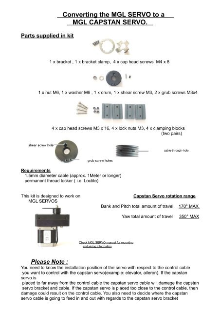
Parts supplied in kitConverting the <strong>MGL</strong> SERVO to a<strong>MGL</strong> CAPSTAN SERVO.1 x bracket , 1 x bracket clamp, 4 x cap head screws M4 x 81 x nut M6, 1 x washer M6 , 1 x drum, 1 x shear screw M3, 2 x grub screws M3x44 x cap head screws M3 x 16, 4 x lock nuts M3, 4 x clamping blocks(two pairs)shear screw holecable-through-holegrub screw holesRequirements1.5mm diameter cable (approx. 1Meter or longer)permanent thread locker ( i.e. Loctite)This kit is designed to work on<strong>MGL</strong> SERVOS<strong>Capstan</strong> Servo rotation rangeBank and Pitch total amount of travel170° MAXYaw total amount of travel350° MAXCheck <strong>MGL</strong> SERVO manual for mountingand wiring informationPlease Note :You need to know the <strong>installation</strong> position of the <strong>servo</strong> with respect to the control cableyou want to control with the capstan <strong>servo</strong>(example: elevator, aileron). If the capstan<strong>servo</strong> isplaced to far away from the control cable the capstan <strong>servo</strong> cable will damage the capstan<strong>servo</strong> bracket and cable. If the capstan <strong>servo</strong> is placed too close to the control cable, thendamage could result on the control cable. You also need to decide where the capstan<strong>servo</strong> cable is going to feed in and out with regards to the capstan <strong>servo</strong> bracket
orientation. Please consider your <strong>installation</strong> carefully11. Removal of output arm1.1 Remove the retaining nut and washer. Fig.11.2 Remove the shear screw. Fig 11.3 Check the collar is clean and free of burs. Fig 2retaining nut and washer.collarFigure 1 Figure 2shear screw.2. Assembly of capstan <strong>servo</strong> parts2.1 Fit clamp and bracket together. Fig 32.2 Place bracket assembly over collar to check that the key hole on thebracket, lines up with one of the four screw holes on the collar.2.3 Place drum into bracket and clamp assembly. Fig 42.4 Please note the side with the large recessed round hole inthe drum is the bottom and this side will go over the collarwhere the output arm was secured.2.5 Let the bracket assembly rest on drum while holding the drum inone hand. Fig 5Place the 4 (4 X 8mm) cap head screw into the slots on the clamp as inFig 6. Line up the screws with four of the eight holes around the collaron the <strong>servo</strong> lid. Keep in mind where you lined up the key hole and collarearlier. Fig 72.6 Turn in the cap head screws a few turns on each screw at a time (toavoid damaging the drum) until the bracket and clamp touch the <strong>servo</strong>lid.----------------------------------------------------------------------------------NB: Please check the alignment of the drum during this process.The drum should slide on easy.-----------------------------------------------------------------------------------2.7 Turn the drum till you see shear screw hole through the key holein the bracket.2.8 Turn in the shear screw , but do not tighten this screw yet! Fig 82.9 Fit the retaining nut and washer. Hold the drum firmly. Turn the nuton
till it tightens, then turn the nut back approximately 1/8 th of a turn. Fig 92.10 Remove the shear screw. Turn the drum slowly to feel if the drummoves with minimal friction against the collar but has no play (wobble).2.11 Refit shear screw and adjust the nut (small adjustments only) , thenremove the shear screw and check the friction again. Repeat untilfeels correct. Note that some collars and drums have a tight and a loosesection in the drums rotation, in this case you will have to find a happymedium.------------------------------------------------------------------------------------NB: When the retaining nut is too tight, causing friction between thedrum and the collar, it will require more force to brake the shearscrew. When the retaining nut is too loose then it may cause thedrum to move (shift) incorrectly, damaging the shear screw andpossibly the drum. The shear screw only works when there isminimal friction and no play between the drum and collar.-----------------------------------------------------------------------------------2.12 Apply a small drop of permanent thread locker (Loctite) to the shearscrew (only enough to wet the last 4 threads of the shear screw).-------------------------------------------------------------------------------------NB: To much permanent thread locker (Loctite) will cause the excess toseep in between the drum and the collar causing the forcerequired to brake the shear screw to increase!-------------------------------------------------------------------------------------2.13 Using the spanner rotate the drum till you see the two smallthreaded holes. These threaded holes are for the grub screwsthat will clamp the cable to the drum. Fig 102.14 Rotate drum till one of the grub screw holes are clear enough toturn in one grub screw and then turn the drum again till the otherhole is visible.2.15 Turn in the grub screws (Fig 11) a few turns. Do not turn thesegrub screws all the way in ,this will stop the cable from goingthrough the cable-through-hole.
33. Fitting the cable cable-through-hole3.1 Turn the drum so you can see the cable-through-hole in thecentre groove on the side of the drumFig 12 (shows through-hole)Align this through-hole across the part of the bracket where thecapstan cable will feed in and out.opposite bracket leg)Fig 13( note through hole is positioned3.2 Feed the capstan cable through the hole. Fig 13(cable fed through through-hole)3.3 Feed the cable in the grooves around the drum till you get throughthe part of the bracket where the through-hole is lined up. Fig 143.4 Repeat the previous step with the other side of the cable,following the grooves in the opposite direction. Fig 15----------------------------------------------------------------------------------NB: If the cable does not fit flush in the grooves all the wayround, then you may have skipped one when feeding thecable between the bracket and drum.-----------------------------------------------------------------------------------3.5 Once cable is threaded through correctly, then feed the cablethrough untill you have an equal or sufficient amount on both sides.3.6 Turn the grub screws tight, clamping the cable into place so itcan't slide. Ref. Fig 10If you need to remove the capstan <strong>servo</strong> parts, follow section 2 and 3 inreverse so as to not cause any damage to the parts.
4. Installing the capstan <strong>servo</strong>.4.1The clamping blocks are designed for clamping a 1.5mm capstan <strong>servo</strong> cableand a 3mm control cable. If a thicker control cable is used in aircraft then file thelarger slot on the pair of clamping blocks deeper. When the pair of clampingblock are put together, the larger hole must be 0.5mm smaller than thecontrol cable thickness.4.2Mount the capstan <strong>servo</strong> in the predetermined location.4.3Check that there is no interference with any of the <strong>servo</strong>s moving partsand capstan <strong>servo</strong> cable.4.4Use one pair of the clamping blocks to clamp the capstan<strong>servo</strong>cable to the control cable on each end, to be controlled. Takenote that the clamping blocks must not be closer than 100mm to the <strong>servo</strong>.Also make sure that the capstan <strong>servo</strong> cable is clamped with no slack.A slack cable will not be able to control the intendedsurface correctly, thus causing wear and could jam up the <strong>servo</strong>.4.5Move the controls from stop to stop to check that the capstan <strong>servo</strong> partsare moving correctly and that there is no interference through out thecontrols range.


