


You also want an ePaper? Increase the reach of your titles
YUMPU automatically turns print PDFs into web optimized ePapers that Google loves.
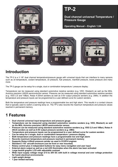
<strong>TP</strong>-2Dual channel universal Temperature /Pressure GaugeOperating <strong>Manual</strong> – English 1.04IntroductionThe <strong>TP</strong>-2 is a 3 1/8” dual channel temperature/pressure gauge with universal inputs that can interface to many sensorssuch as oil temperature, coolant temperature, oil pressure, fuel pressure, manifold pressure, boost pressure and manymore.The <strong>TP</strong>-2 gauge can be setup for a single, dual or combination temperature / pressure display.Temperature can be measured using standard automotive resistive senders (e.g. VDO, Westach) as well as the <strong>MGL</strong><strong>Avionics</strong> precision LM335 semiconductor sensor. Pressure can be measured using standard automotive resistive senders(e.g. VDO 2,5 and 10Bar), Rotax 4-20mA senders as well as 0-5V output pressure senders (e.g. UMA). In addition thetemperature and pressure inputs can be programmed to a user defined curve for custom senders.Both the temperature and pressure readings have a programmable low and high alarm. This results in a contact closurethat is typically used to switch a warning lamp on. The <strong>TP</strong>-2 also records the maximum temperature and pressure valuesreached in permanent memory.1 Features• Dual channel universal input temperature and pressure gauge• Temperature can be measured using standard automotive resistive senders (e.g. VDO, Westach) as wellas the <strong>MGL</strong> <strong>Avionics</strong> precision LM335 semiconductor sensor• Pressure can be measured using standard automotive resistive senders (e.g. VDO 2,5 and 10Bar), Rotax 4-20mA senders as well as 0-5V output pressure senders (e.g. UMA)• Temperature and pressure inputs can be programmed to a user defined curve for custom senders• Can be setup for a single, dual or combination temperature / pressure display.• Both temperature and pressure readings have a programmable low and high alarm• Records maximum temperature and pressure reached in permanent memory• Supports Rotax 4-20mA pressure sender as used in 912/914 engines• Standard 3 1/8” aircraft enclosure (can be front or rear mounted)• Rotary control plus 2 independent buttons for easy menu navigation and user input• External alarm output as well as a red LED illuminates when the alarm has been activated• Large backlit graphic LCD with adjustable contrast• Wide input supply voltage range of 8 to 30V DC with built in voltage reversal and over voltage protectionfor harsh electrical environments• Light weight design• 1 year limited warranty
<strong>TP</strong>-2 Operating <strong>Manual</strong> Page 22 <strong>TP</strong>-2 LayoutBacklit Graphic LCD Display:Contrast and backlight can be adjustedin the menu systemLED Alarm:The red LED will illuminate if any of thealarm set points have been exceededHarness:Harness connects to power,temperature and pressuresendersUp/F1 Button:Up button in menu systemDisplay maximum temperatureand pressure values in normalmodeDown/F2 Button:Down button in menuSystem. Adjust contrastin normal modeRotary Control (Up/Down) & Enter Button:Press the rotary control during normal mode to access the menu system. Rotate anti/clockwisefor up/down menu scrolling. During normal mode rotating the rotary control will toggle between thetemperature and pressure display (only if Single display mode is selected).
<strong>TP</strong>-2 Operating <strong>Manual</strong> Page 64 Menu SystemPressing the rotary control button during the normal display mode will cause the <strong>TP</strong>-2 to enter the menu system. Use theup/down keys or the rotary control to navigate through the menu system.4.1 Exit MenuPressing the rotary control on this menu item will cause the <strong>TP</strong>-2 to exit the menu system. Allchanges made during navigation of the menu system will be saved in non-volatile memory onexiting the menu system. If you remove power before exiting the menu the instrument will notsave any changes.4.2 Display SetupMove the highlight over this menu item and press the rotary button to return to the main menu.Select this menu option to adjust the display contrast.Select this menu option to turn the backlight on or off.If “SINGLE” is selected then only temperature or pressure is shown at one time. If “DUAL” isselected then both temperature and pressure are shown on the same screen.Select whether you want the temperature and pressure bar to be shown vertically or horizontally.Select whether you want the single temperature/pressure display to alternate automatically ormanually. This display is only shown if display mode is setup to show “SINGLE”.
<strong>TP</strong>-2 Operating <strong>Manual</strong> Page 7Set the time that the single display modes must be displayed for. This display is only shown ifauto is selected for the display mode.4.3 Channel 1 / Channel 2 SetupThe <strong>TP</strong>-2 can be setup to display temperature or pressure for each individual input channel.Setup is shown for Channel 1, Channel 2 is identical in setupMove the highlight over this menu item and press the rotary button to return to the main menu.Select what type of sender is connected to the input channel. Selectbetween pressure, temperature or off.4.3.1 Pressure SetupMove the highlight over this menu item and press the rotary button to return to the main menu.Select if you are using a resistive, 4-20mA or 0-5V output pressure sender.If the “Resistive” pressure sender is selectedSelect what type of resistive pressure sender you are using. Select “VDO” for VDO / resistivesenders, “USER” for a custom sender.Select which VDO pressure sender you are using. A selection between a VDO 2, 5 or 10 Bar canbe selected.
<strong>TP</strong>-2 Operating <strong>Manual</strong> Page 8If the “0-5V” pressure sender is selectedSelect the type of 0-5V sender used. Select “UMA” for UMA senders of “USER” for a custom0-5V sender.For UMA senders select the UMA model number.If the “4-20mA” pressure sender is selectedPlease note that only 1 4-20mA pressure sender can be interfaced to the <strong>TP</strong>-2.Select the type of 4-20mA sender used. Select “ROTAX” for Rotax 912/914 4-20mA sender or“USER” for a custom 4-20mA sender.Enter the pressure specified at 4mA output.Enter the pressure specified at 20mA output.If the “User” pressure sender is selectedA custom sensor can be interfaced to the <strong>TP</strong>-2. This sensor can be a resistive, 4-20mA or 0-5Vsender.If the sender type is set to “USER”, then use this menu option to calibrate your pressure sender.See section 4.3.3 for more information.Menu options for all sender typesChoose one of a selection of labels to suit your pressure input so you can identify it easily.Select whether you want to display the pressure in Bar, PSI or PSI(0.1). The PSI(0.1) is for lowrange pressure senders e.g. UMA 7PSI.
<strong>TP</strong>-2 Operating <strong>Manual</strong> Page 9Set the range of the pressure sender. This is the maximum that the bargraph display will go to.This allows the user to zoom into the top half of the bar graph resulting in a higher displayresolution. This option set to “ON” is recommended.Select whether to use the low pressure alarm.Use this to set the low pressure alarm set-point.Select whether to use the high pressure alarm.Use this to set the high pressure alarm set-point.4.3.2 Temperature SetupSelect what type of sender you are using. Select “VDO” a VDO resistive sender, “WESTACH” forWestach thermistor type senders, “<strong>MGL</strong>” for a <strong>MGL</strong> NTC resistive temperature sender, LM335for a <strong>MGL</strong> precision temperature sender or “USER” for a custom sender. The <strong>TP</strong>-2 has a built inlinearization curve for a standard 50ºC to 150ºC VDO resistive sender as well as for the <strong>MGL</strong>NTC resistive sender.If the sender type is set to “User”If the sender type is set to “USER”, then use this menu option tocalibrate your temperature sender. See section 4.3.3 for moreinformation.If the sender type is set to “LM335”If the sender type is set to LM335, then use this menu option to calibrate your LM335 precisiontemperature sender. If recalibration is required then adjust the value using the up/down keys orthe rotary control until the temperature matches the reference ambient temperature. Please notethat the LM335 can only be calibrated in degrees Celcius irrespective if the <strong>TP</strong>-2 is setup todisplay temperature in Fahrenheit.
<strong>TP</strong>-2 Operating <strong>Manual</strong> Page 10Menu options for all sender typesChoose one of a selection of labels to suit your temperature input so you can identify it easily.Select whether you want the temperature to be displayed in degrees Celcius (ºC) or in degreesFahrenheit (ºF).Set the range of the temperature sender. This is the maximum that the bargraph display will goto.This allows the user to zoom into the top half of the bar graph resulting in a higher displayresolution. This option set to “ON” is recommended.Select whether to use the low temperature alarm.Use this to set the low temperature alarm set-point.Select whether to use the high temperature alarm.Use this to set the high temperature alarm set-point.4.3.3 Calibrating the user defined pressure and temperature sender1. Enter the number of points that you want to calibrate.2. Enter the display reading that you want to show when the sender is at that actual displayreading.3. Enter the ADC (analog to digital converter) reading that corresponds to this display reading.The ADC reading is shown at the top of the calibration menu if you are applying the actualstimulus from the temperature or pressure sender. You can also manually enter this value ifthe ADC value is known or pre-calculated.4. Continue entering display and ADC values until all the points have been entered.5. Verify the above calibration by checking the temperature/pressure display versus the actualapplied sender stimulus.
<strong>TP</strong>-2 Operating <strong>Manual</strong> Page 115 Loading Factory default settingsPressing and holding the F1 and F2 keys simultaneously on power up will cause the <strong>TP</strong>-2 to load preprogrammed factorydefault settings. The following screen will be displayed:6 Operating the alarmsIf the alarm is activated, the corresponding item on the display will flash. At the same time the externally available alarmswitch will close. The switch will remain closed until any button is pressed to acknowledge the alarm or until thecondition(s) that activated the alarm no longer exist. The alarm output can be used to switch an external alarm indicator.The external alarm switch is an open collector transistor switch to ground with a maximum rating of 0.5A DC. It is possibleto wire the alarm contacts of several Stratomaster instruments in parallel should this be desired. To avoid false activationof the alarms, the alarm function is only active 10 seconds after the instrument has powered up.7 CleaningThe unit should not be cleaned with any abrasive substances. The screen is very sensitive to certain cleaning materialsand should only be cleaned using a clean, damp cloth.Warning: The <strong>TP</strong>-2 is not waterproof. Serious damage could occur if the unit is exposed to waterand/or spray jets.
<strong>TP</strong>-2 Operating <strong>Manual</strong> Page 128 <strong>TP</strong>-2 SpecificationsOperating Temperature RangeStorage Temperature RangeHumidityPower SupplyCurrent ConsumptionDisplayADCDimensionsEnclosureWeightAlarm contact current ratingNon-volatile memory storageTemperature sensors-10ºC to 50ºC (14ºF to 122ºF)-20ºC to 80ºC (-4ºF to 176ºF)
<strong>TP</strong>-2 Operating <strong>Manual</strong> Page 139 InstallationTemperature sendersFive types of temperature senders can be fitted:VDO Resistive senders: A standard 50ºC to 150ºC VDO resistive automotive sender can be used.<strong>MGL</strong> NTC resistive senders: A suitable sender with the same thread used by Rotax can be obtained from <strong>MGL</strong><strong>Avionics</strong> (manufacturer Echlin).Most NTC senders require a single wire connected as shown. The sender is grounded via the engine block. The groundterminal of the gauge input should be connected to the engine block. Some NTC senders have two wires. In this case it isnot required that the sender housing itself is connected to the engine block. Wire the second wire to the reference groundterminal.<strong>MGL</strong> Precision senders (National Semiconductors LM335): These are senders containing asemiconductor temperature measurement device. They can be used for water or oil temperature. These senders areavailable in two types: an encapsulated version with a brass housing suitable for Rotax thread; a second uncommittedversion contains only the sensor itself. This can be conveniently mounted inside an existing sender housing after youremove the original insides of the sender. This is intended to give you a solution for unusual or difficult to obtain senders.Connect the Black wire to ground, the Red or green wire to the channel input.Westach Resistive senders: The <strong>TP</strong>-2 supports the Westach thermistor type senders.User defined senders: The <strong>TP</strong>-2 has a user sender calibration feature that can be customized for senders not listedabove.Connect the temperature sender to the orange (Pin 2) or green (Pin 3) wire on the DB9 connectorPressure sendersFour types of pressure senders can be fittedVDO Resistive senders: The <strong>TP</strong>-2 includes linearisation curves for the VDO 2, 5 and 10 Bar pressure senders.Connect your VDO/resistive sender to the orange (Pin 2) or green (Pin 3) wire on the DB9 connector.4-20mA Pressure Senders: The <strong>TP</strong>-2 supports the 4-20mA pressure sender as used in Rotax 912/914 enginesConnect your VDO 4-20mA senders white wire to the yellow wire on the DB9 connector (Pin 8).0-5V output senders: e.g. UMA that can be used with the <strong>TP</strong>-2 are those types that have their maximum outputvoltage of 5V at their maximum pressure output. The <strong>TP</strong>-2 has built in linearisation curves for the UMA T1EU07, T1EU35,T1EU70A , T1EU70, T1EU100 and T1EU150Connect your UMA/Voltage output sender to the orange (Pin 2) or green (Pin 3) wire on the DB9 connector.User defined senders: The <strong>TP</strong>-2 has a user sender calibration feature that can be customized for Resistive, 4-20mA as well as Voltage output senders.
<strong>TP</strong>-2 Operating <strong>Manual</strong> Page 14Senders that are grounded in the engine blockSingle wire senders require that their mounting arrangement (thread) has a very good electrical contact with the engineblock. Avoid the use of any sealant or tapes as these may cause a bad electrical connection. Further to this it is veryimportant that the engine block has a good electrical connection to the negative supply terminal of the <strong>TP</strong>-2. Any voltagedrop caused by other equipment on the ground wire will cause incorrect readings. The best way to ensure a goodconnection is to wire a single connection between the <strong>TP</strong>-2 ground terminal (any of these terminals) and the engine block.Do not wire this anywhere else and do not allow any other equipment to use this wire as a current return path.9.1 Connection DiagramThe use of an external 1A fuse is recommended. Connect the supply terminals to your aircrafts power supply. The <strong>TP</strong>-2can be used on both 12V and 24V without the use of any pre-regulators. Ensure that the supply voltage will not dropbelow 8V during operation as this may result in incorrect voltage and or current readings.
<strong>TP</strong>-2 Operating <strong>Manual</strong> Page 159.2 UMA Voltage output pressure sender (0 to 5V output)Pinout:White/Red: +12VWhite: SignalWhite/Blue: GroundShield: Ground9.3 ROTAX 912/914 4-20mA Pressure senderThe sensor cable is approximately 3m long and has 3 leads. The black lead is not to be connected and has no function.The Red lead from the sensor has to be connected to the positive bus via a fuse or circuit breaker . The white lead(Output signal) has to be connected directly to the <strong>TP</strong>-2 Yellow wire (Pin 8).9.4 <strong>TP</strong>-2 DB9 Cable connectionsDB 9 Pin Color Function1 Black Ground2 Orange Channel 1 input (Pressure andTemperature sender input, resistive and0-5V)3 Green Channel 2 input (Pressure andTemperature sender input, resistive and0-5V input)4 NC Airtalk communication (Not connected)Used for firmware upgrading6 Red 8-30Vdc power8 Yellow Pressure Sender input (4-20mA)9 White Alarm Output
<strong>TP</strong>-2 Operating <strong>Manual</strong> Page 1610 WarrantyThis product carries a warranty for a period of one year from date of purchase against faulty workmanship or defectivematerials, provided there is no evidence that the unit has been mishandled or misused. Warranty is limited to thereplacement of faulty components and includes the cost of labor. Shipping costs are for the account of the purchaser.Note: Product warranty excludes damages caused by unprotected, unsuitable or incorrectly wiredelectrical supplies and or sensors, and damage caused by inductive loads.11 DisclaimerOperation of this instrument is the sole responsibility of the purchaser of the unit. The user must make themselves familiarwith the operation of this instrument and the effect of any possible failure or malfunction.This instrument is not certified by the FAA. Fitting of this instrument to certified aircraft is subject to the rules andconditions pertaining to such in your country. Please check with your local aviation authorities if in doubt. This instrumentis intended for ultralight, microlight, homebuilt, experimental and light sport aircraft. Operation of this instrument is the soleresponsibility of the pilot in command (PIC) of the aircraft. This person must be proficient and carry a valid and relevantpilot’s license. This person has to make themselves familiar with the operation of this instrument and the effect of anypossible failure or malfunction. Under no circumstances does the manufacturer condone usage of this instrument for IFRflights.The manufacturer reserves the right to alter any specification without notice.Other instruments in the Stratomaster Velocity seriesALT-3 Encoding aviation altimeter and Vertical speed indicator (VSI)ALT-4 Encoding aviation altimeter with Serial RS232 & Parallel Gillham code outputASI-3 Airspeed indicator (ASI) with automatic flight logASX-2 Encoding aviation altimeter and Airspeed indicator (ASI)AV-2 Artificial horizon and magnetic compass indicatorE-1 Universal engine monitorFLIGHT-2 Primary Flight instrumentFF-3 Fuel Computer (single or dual fuel tanks)GF-2 +-10G tilt compensated dual range G-force meterMAP-2 Manifold pressure and RPM IndicatorROTOR-1 Dual Rotor / Engine tachometerRTC-1 Aviation real time clock (RTC), outside air temperature (OAT) and Voltage displayRV-3 Universal engine / Rotor RPM IndicatorTC-2 4-Channel thermocouple (EGT/CHT) indicatorTC-3 12-Channel thermocouple (EGT/CHT) indicator<strong>TP</strong>-2 Universal temperature and pressure gauge


