Installat Instruction: Auxilliary Xenon Light BMW ... - Touratech-USA
Installat Instruction: Auxilliary Xenon Light BMW ... - Touratech-USA
Installat Instruction: Auxilliary Xenon Light BMW ... - Touratech-USA

Create successful ePaper yourself
Turn your PDF publications into a flip-book with our unique Google optimized e-Paper software.
01-040-1516-0<br />
1<br />
Lieferumfang:<br />
März 2006<br />
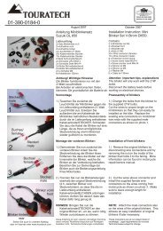
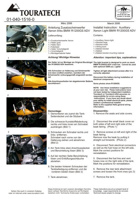
Anleitung Zusatzscheinwerfer<br />
<strong>Xenon</strong> links <strong>BMW</strong> R1200GS ADV<br />
1 x Zusatzscheinwerfer <strong>Xenon</strong><br />
1 x Halter groß<br />
1 x Halter klein<br />
1 x Kabelsatz<br />
1 x Halter Vorschaltgerät<br />
1 x Vorschaltgerät<br />
1 x Montagematerial Halter<br />
Achtung! Wichtige Hinweise<br />
March 2006<br />
DIN EN ISO 9001:2000<br />
Zertifikat 15 100 42285<br />
<strong>Installat</strong> <strong>Instruction</strong>: <strong>Auxilliary</strong><br />
<strong>Xenon</strong> <strong>Light</strong> <strong>BMW</strong> R1200GS ADV<br />
Contains:<br />
1 x <strong>Auxilliary</strong> <strong>Xenon</strong> light<br />
1 x Bracket large<br />
1 x Bracket small<br />
1 x Wiring loom<br />
1 x Ballast bracket<br />
1 x Ballast<br />
1 x Ballast bracket mounting material<br />
Attention: important tips, explanations<br />
Der Halter ist zur Montage am Original-Sturzbügel<br />
der R1200GS ADV bestimmt.<br />
Alle Schrauben an Halterung und Scheinwerfer<br />
erst dann endfest anziehen, nachdem der<br />
Scheinwerfer ordnungsgemäß eingestellt worden<br />
ist!<br />
Alle Anschlussarbeiten bei abgeklemmter Batterie<br />
durchführen!!<br />
The light bracket is designed to work on stock<br />
<strong>BMW</strong> R1200GS ADV crash bar. Cannot be used<br />
with optional OEM aux. <strong>Light</strong>s!<br />
Tighten all light attachment screws after it is<br />
correctly adjusted.<br />
Disconnect the battery during installation of<br />
electrical components.<br />
Some photos show R1200GS.<br />
2<br />
NOTE: Use these installation suggestions<br />
at your own risk. These instructions have<br />
not been tested by independent installers.<br />
<strong>Touratech</strong> or <strong>Touratech</strong>-<strong>USA</strong> assumes no<br />
responsibility for errors using these<br />
instructions. If you have any doubt about<br />
your ability to install electrical parts, please<br />
contact a professional installer.<br />
Refer to the supplied Hella general wiring<br />
information.<br />
3<br />
Demontage:<br />
1. Demontieren sie zuerst die Tank-<br />
Seitendeckel und die Sitzbank<br />
2. Die schwarze Kunststoffabdeckung<br />
rechts und links innen am Schnabel<br />
aushängen (Bild 1)<br />
3. Schrauben am Schnabel rechts und<br />
links entfernen.<br />
Schnabel nach vorne von der<br />
Halterung ziehen und abnehmen<br />
(Bild 2)<br />
4. Am Tank links oben Anschlussstecker<br />
und Benzinleitung lösen (Bild 3)<br />
5. Auf der rechten Seite Benzinleitung<br />
lösen und Entlüftungsschläuche<br />
abziehen<br />
6. Die beiden hinteren Schrauben der<br />
Tankbefestigung entfernen und die<br />
vorderen beiden lösen (Bild 3)<br />
7. Tank abnehmen<br />
Disassembly:<br />
1. Remove the seats and side covers.<br />
2. Disconnect the small black cover on<br />
both sides of left and right side of the<br />
beak fairing. (Photo 1)<br />
3. Remove screws on left and right of the<br />
beak fairing.<br />
Remove now the beak by pulling it<br />
straight out forwards. (Photo 2)<br />
4. Disconnect Tank electrical connectors<br />
as well as the fuel hose on the left side.<br />
Mark the correct positions for<br />
reinstallation.<br />
5. Disconnect the fuel line and vent<br />
hoses now on the right side of the tank.<br />
Mark the positions for reinstallation.<br />
6. Remove the rear tank attachment<br />
screws and loosen the front ones (pic.3)<br />
7. Remove the tank.<br />
Sehen Sie auch in unserem Katalog<br />
oder im Internet unter www.touratech.com<br />
Diese Anleitung ist nach unserem derzeitigen Kenntnisstand<br />
verfasst. Rechtliche Ansprüche auf Richtigkeit<br />
bestehen nicht. Technische Änderungen vorbehalten.<br />
These instructions are at our present level of<br />
knowledge. Legal requirements do not exist.<br />
Technical issues subject to change.
01-040-1516-0<br />
DIN EN ISO 9001:2000<br />
Zertifikat 15 100 42285<br />
1<br />
A<br />
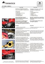
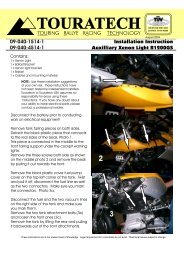
Montage des Halters:<br />
1. Scheinwerferhalterung wie in Bild 1<br />
vormontieren (Abbildung zeigt Halter<br />
rechts)<br />
<strong>Installat</strong>ion of light bracket:<br />
1. Install the light bracket as shown on<br />
photo 1. (Photo shows right side<br />
bracket)<br />
B<br />
1 x Halter groß (A)<br />
1 x Halter klein (B)<br />
2 x Linsenkopfschraube M6 x 18<br />
4 x U-Scheibe M6 groß<br />
2 x Mutter selbstsichernd M6<br />
1 x Bracket large (A)<br />
1 x Bracket small (B)<br />
2 x Screw dome head M6 x 18<br />
4 x Washer large M6<br />
2 x Self securing nylock nut M6<br />
2<br />
2. Scheinwerferhalterung wie in Bild 2<br />
unterhalb des Sturzbügels mit den<br />
beigelegten Schellen befestigen (je<br />
nach Ausführung links oder rechts).<br />
2. <strong>Light</strong> bracket will be installed under the<br />
crashbar with supplied pipe clamps as<br />
shown on photo 2. (Photo shows right<br />
side bracket)<br />
2 x Rohrschelle gummiert<br />
4 x Schraube Flachrundkopf M6 x 16<br />
4 x U-Scheibe M6 groß<br />
4 x Mutter selbstsichernd M6<br />
2 x Pipe clamp rubberized<br />
4 x Screw flat round head M6 x 16<br />
4 x Washer large M6<br />
4 x Self securing nylock nut M6<br />
3<br />
Hinweis:<br />
Falls unser Ölkühlerschutz verwendet<br />
wird, muss evtl. jeweils die Gummierung<br />
an der inneren Schelle wie in Bild 2 und 3<br />
entfernt werden! (Abbildung zeigt Halter<br />
rechts)<br />
Note:<br />
It may be necessary to remove the inner<br />
rubber off the pipe clamp if <strong>Touratech</strong> oil<br />
cooler guard is used as shown on photos<br />
2+3. (Photo shows right side bracket).<br />
4<br />
3. Scheinwerfer mit den beigelegten<br />
Schrauben an der Halterung<br />
befestigen (Bild 4). Die komplette<br />
Halterung so auf dem Sturzbügel<br />
verschieben, dass der Scheinwerfer<br />
näher am Schnabel steht (Bild 4 und 5)<br />
3. Attach the light on the bracket with<br />
supplied hardware (photo 4). Push now<br />
the light with bracket on the crash bar so<br />
that it is close to the beak. (Photo 4+5)<br />
5. Lösen sie jetzt die am Scheinwerfer<br />
befestigte Blende. Dies erleichtert den<br />
Anschluss!<br />
5. Remove the aluminum guard on the<br />
side of the light to make further<br />
installation easier.<br />
5<br />
Sehen Sie auch in unserem Katalog<br />
oder im Internet unter www.touratech.com<br />
Diese Anleitung ist nach unserem derzeitigen Kenntnisstand<br />
verfasst. Rechtliche Ansprüche auf Richtigkeit<br />
bestehen nicht. Technische Änderungen vorbehalten.<br />
These instructions are at our present level of<br />
knowledge. Legal requirements do not exist.<br />
Technical issues subject to change.
01-040-1516-0 / 01-040-4516-0<br />
DIN EN ISO 9001:2000<br />
Zertifikat 15 100 42285<br />
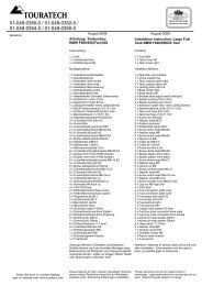
Elektrischer Anschluss:<br />
Electrical connection:<br />
Den Anschlussstecker des<br />
Vorschaltgerätes zum Vorschaltgerät<br />
ziehen und anschließen (Bilder beachten!)<br />
Connect the ballast power supply cable<br />
to the ballast as shown on the photos<br />
left.<br />
Correct<br />
Incorrect<br />
Rotes Kabel mit Ringöse zu Batterie-Plus<br />
ziehen, braunes Kabel zu Batterie-Minus<br />
ziehen. Relais in den Werkzeugkasten<br />
unter der Sitzbank, oder an einen<br />
geeigneten Platz unter dem Tank legen,<br />
ebenso den Sicherungsschalter!<br />
Kabel auf die passende Länge kürzen.<br />
Gelb/graues Kabel nach vorne zum<br />
Scheinwerferanschluss ziehen. Die<br />
schwarze Kabelhülle hinter dem<br />
Scheinwerfer-Anschlussstecker vorsichtig<br />
aufschneiden. Das gelb/graue Kabel mit<br />
dem Kabelverbinder am weißen<br />
Fernlichtkabel anschließen.<br />
Kabelhülle wieder mit Isolierband<br />
zukleben.<br />
Alle Kabel mit Kabelbindern sichern und<br />
Tank wieder montieren.<br />
Route the red wire to the battery positive<br />
pole, the two brown wires to the negative<br />
pole. Place the relay in the cavity by the<br />
ABS unit under the tank and the fuse<br />
right side behind the black plastic side<br />
cover where the fuses are easily<br />
accessible.<br />
Cut the wires to right lenght.<br />
Note two options for headlight<br />
connection! 1st option - carefully open<br />
the wireloom cover behind headlight.<br />
Attach yellow/gray wire with scotch lock<br />
connector to the white highbeam wire.<br />
2nd option - Route yellow/gray cable to<br />
the headlight. Remove the plastic cover<br />
behind the high beam. Carefully drill a<br />
10mm or 3/8" hole in the plastic headlight<br />
housing. There is a good flat spot right<br />
below the high beam cover next to the<br />
connector. It is also good to use 1/4"<br />
rubber hole grommets to protect and<br />
insulate the hole (grommets are not<br />
supplied in the package).<br />
Route the yellow/gray cable thru the hole<br />
and connect it to the white high beam<br />
cable with supplied scotchlock<br />
connectors inside the highbeam housing.<br />
Put the plastic cover back behind the<br />
highbeam or use electrical tape to protect<br />
connection if 1st option is used.<br />
Secure all wires with zip ties.<br />
Der Scheinwerfer ist Typ-geprüft und<br />
besitzt das E- und SAE-Prüfzeichen auf<br />
der vorderen unteren Einfassung des<br />
Scheinwerferglases.<br />
The light has E and SAE approvals on<br />
the underside of the black ring around<br />
the light glass.<br />
SAE Y 00 TF 40, 1120 E1 17 5 DR 00<br />
SAE Y 00 TF 40, 1120 E1 17 5 DR 00<br />
Sehen Sie auch in unserem Katalog<br />
oder im Internet unter www.touratech.com<br />
Diese Anleitung ist nach unserem derzeitigen Kenntnisstand<br />
verfasst. Rechtliche Ansprüche auf Richtigkeit<br />
bestehen nicht. Technische Änderungen vorbehalten.<br />
These instructions are at our present level of<br />
knowledge. Legal requirements do not exist.<br />
Technical issues subject to change.
01-040-1516-0<br />
DIN EN ISO 9001:2000<br />
Zertifikat 15 100 42285<br />
1<br />
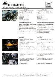
Montage Vorschaltgerät:<br />
1. Vormontage der beiden Elastikpuffer<br />
wie in Bild 1<br />
<strong>Installat</strong>ion of ballast:<br />
1. Preassembly of both elastic-rubbers<br />
as shown in pic. 1<br />
2. Vorschaltgerätehalterung wie in Bild2<br />
mit Original-Ölleitungsschraube und<br />
Kabelbinder auf der Benzinpumpe<br />
befestigen<br />
2. Install the ballast bracket at the left<br />
side (040-1516) on the fuel pump as<br />
show in picture 2. Using original oil line<br />
screw and cable tie.<br />
2<br />
3. Vorschaltgerät einlegen und mit dem<br />
O-Ring am Halter befestigen (Bild 3)<br />
4. Kabel wie in Bild 4 zum Scheinwerfer<br />
ziehen und anschließen<br />
3. Put the ballast in the bracket and<br />
secure it with the O-Ring (pic.3).<br />
4. Route the high voltage cable as shown<br />
in picture 4 to the HID light.<br />
5. Anschlusskabel mit Kabelbindern am<br />
Vorbauträger fixieren (Bild 4)<br />
5. Secure the cable with zip ties (pic.4)<br />
Hinweis:<br />
Bajonett-Verschluss!<br />
Note:<br />
Study carefully how the connector<br />
attaches to the HID light!<br />
3<br />
Jetzt alles an die Batterie anschließen und<br />
auf Funktion prüfen!<br />
<strong>Xenon</strong>-Zusatzscheinwerfer sollte jetzt mit<br />
dem normalen Fernlicht zusammen<br />
aufleuchten.<br />
Connect the wiring to the battery and test<br />
the light.<br />
HID should work with the high beam.<br />
Seitenteile und Sitzbank wieder anbauen!<br />
Reinstall tank, all fairing pieces and seat!<br />
4<br />
Sehen Sie auch in unserem Katalog<br />
oder im Internet unter www.touratech.com<br />
Diese Anleitung ist nach unserem derzeitigen Kenntnisstand<br />
verfasst. Rechtliche Ansprüche auf Richtigkeit<br />
bestehen nicht. Technische Änderungen vorbehalten.<br />
These instructions are at our present level of<br />
knowledge. Legal requirements do not exist.<br />
Technical issues subject to change.