How to Install (pdf) - Touratech-USA
How to Install (pdf) - Touratech-USA
How to Install (pdf) - Touratech-USA
- No tags were found...

You also want an ePaper? Increase the reach of your titles
YUMPU automatically turns print PDFs into web optimized ePapers that Google loves.
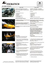
IMO-100 R300 Opera<strong>to</strong>r’s Manualand Assembly InstructionsThe IMO-100 R300 is an electronic all-in-one instrument <strong>to</strong> be installed in your vehicle. It can beused as a replacement for he instrument block or as an additional instrument. Besides theregular function of the speedometer and odometer, the IMO-100 R300 provides information ondistance and calculates fuel usage. The sport driver may find the acceleration and maximumspeed functions as well as the s<strong>to</strong>p watch function useful. Additionally there is an outsidetemperature gauge. Finally the computer provides information on the condition of he mo<strong>to</strong>rcycle,including engine temperature and battery life.You can utilize the computer as a rally computer. This function, which you can be used forcourse description, can be programmed by the driver with the assistance of road books. TheIMO-100 R300 has proven <strong>to</strong> be a worthwhile rally computer during the <strong>to</strong>ughest rallies in theworld.Copyright byTOURATECHHerbert Schwarz and Jochen SchanzPO Box 1082D-78074 NiederschachF.R. GermanyTel: +49 (0) 77 28 / 92 79 – 0Fax: +49 (0) 77 28 / 92 79 - 29E-mail: info@<strong>to</strong>uratech.deThis manual shall neither be copied nor distributed without explicit permission with the exceptionof brief reference during technical meetings.Page 2
IMO-100 R300 Opera<strong>to</strong>r’s Manualand Assembly Instructions2. Basic Setting of the IMO-100 R300 (Adapting <strong>to</strong> Your Vehicle)2.1 Start in the Basic FunctionAre you in the Basic Function? > Continue <strong>to</strong> “Parametrization” 2.2Are you in the Road Book Function? > Use the ⇓ key <strong>to</strong> move <strong>to</strong> the Basicfunction, Continue <strong>to</strong>“Parametrization” 2.2Are you in any other function?> Press the ⇓ key until you are in theBasic Function. Continue <strong>to</strong>“Parametrization” 2.22.2 Parametrization:Hold down the E key (editing see 1.2.1) approximately one (1) second. Now youshould be in the first edit field, “Time, Hour”. The first edit field is blinking. Pressthe E key again and move <strong>to</strong> the next field. If using the remote control, you mayuse the +/- key <strong>to</strong> move <strong>to</strong> the next field.2.2.1 Time:The hours flash and can be altered using the ⇑ and ⇓ keys. Press the Ekey <strong>to</strong> enter the minute field. Press the E key again and you will enterthe date field.2.2.2 Date:The day flashes and can be changed using the ⇑ and ⇓ keys. Press theE key and enter the month field. Press again <strong>to</strong> change the year. Eagain and you will enter the next field.2.2.3 Wheel Size:The wheel circumference size in mm must be entered here. Use the ⇑and ⇓ keys <strong>to</strong> enter the value and E <strong>to</strong> move the next field.2.2.4 Warning Temperature:Setting the Warning Temperature. Even here, each blinking field ischanged using the ⇑ and ⇓ keys. You can set the desired warningtemperature or select 000 <strong>to</strong> turn the option off. If you reach the warningtemperature, the display will switch <strong>to</strong> the Engine Specifications Displayregardless of the display you are in. If you’ve selected 000, you will seeWarning Temperature “off” in the Engine Specifications Display (see3.11).2.2.5 Lighting Genera<strong>to</strong>r Warning Function:This warning function can be turned off using the ⇑ and ⇓ keys. If thewarning is turned on, and the display is faltering, the display will switch <strong>to</strong>the Engine Specifications display regardless of the display you are in.2.2.6 Total Kilometer Reading:These are the <strong>to</strong>tal amount of km that your mo<strong>to</strong>rcycle has covered.Follow the directions for the wheel size and enter the <strong>to</strong>tal km readingfrom your mo<strong>to</strong>rcycle.2.2.7 Road Book Display:You may choose (using the ⇑ and ⇓ keys) whether you would like yourstretch or the <strong>to</strong>tal distance driven shown in large font. (see 3.12)2.2.8 Adapting the Rev Counter:Correction Rotation appears in the display. Normally the divisor is 1.Entering “0.5” means that the value of speed displayed later is doubled.If “2” is entered, the value is halved, if you enter”3”, the value is dividedby 3, and so on. Depending on the ignition system and number ofcylinders, the speed must be adapted.Page 6
IMO-100 R300 Opera<strong>to</strong>r’s Manualand Assembly Instructions3. Operating the Functions3.1 Basic Function – the basic function is intended <strong>to</strong> completely replace the vehicleinstrument gauges.• Speed• RPMs• Time and dateThe function is located in the <strong>to</strong>p right corner (as in all following functions). Toenter in<strong>to</strong> the Parametrization Function of the IMO, you must be in this functionand you can only enter the Road Book function from here.3.1.1 Possibilities within this Function• On the IMO-100 R300• ⇑ Key: The ⇑ key allows you <strong>to</strong> enter the Road Book Function.There are no other alternatives <strong>to</strong> activate Road Book (see 3.12).• ⇓ Key: The ⇓ key allows you <strong>to</strong> switch <strong>to</strong> the next function whichin this case, is the Short Distance Function (see 3.2)• E Key: Hold it down for approximately one (1) second <strong>to</strong> activatethe parametrization (see 2.2).• With the Remote Control (see 8.2)• +/- Key: You can also enter the next function by pressing the +/- .The – will take you <strong>to</strong> Short Distance Function (02), and the +key will take you <strong>to</strong> Engine Specifications (11) as long as youhave selected this during parametrization. Otherwise you willenter the next function you chose.• 0 Key: This key does not have a purpose in this Function.3.2 Short Distance – The Short Distance Function is a counter, which can be resetat any time.Additionally, this function displays:• Average speed without breaks (breaks are deducted from the calculation)• Actual drive time since the counter was resetSecond Calculation:• Average speed with breaks (breaks are included in calculation)• Break time since beginning of the drive.3.2.1 Possibilities within this Function• On the IMO-100 R300• ⇑ Key: Switches the display <strong>to</strong> the previous function, BasicFunction (01)• ⇓ Key: Switches the display <strong>to</strong> the next function, Short Distance(03)• E Key: Resets the course time back <strong>to</strong> zero, thereby alsoresetting the average speed and times back <strong>to</strong> zero.• With the Remote Control• +/- Key: Switches you <strong>to</strong> the previous or next• 0 Key: Resets the Short Distance Function (like E key on device)New calculations after resetting require a minimum of one-minute drivetime and one km driving distance. Break times can only be calculatedafter this point.Page 8
3.2.2 Hint: The Short Distance Function can be utilized as an “au<strong>to</strong>matics<strong>to</strong>pwatch” for lap times in mo<strong>to</strong>r cross or races: When starting, resetvalues <strong>to</strong> zero and upon reaching destination, record exact time (down <strong>to</strong>the second).3.3 Daily KilometerThe daily km counter displays the average speed driven since 12:00:01 am. Thisis a daily km counter.Additional info:• Average speed without breaks (breaks are deducted from calculation)• The actual drive time since 12 a.m. of that day.2 nd Calculation:• Average speed with breaks (breaks are included in calculation)• Total break time since the beginning of the day.3.3.1 Possibilities within this Function• On the IMO-100 R300• ⇑ Key: Switches the display <strong>to</strong> the previous function, ShortDistance Function (02)• ⇓ Key: Switches the display <strong>to</strong> the next function, Long Distance(04)• E Key: No function• With the Remote Control• +/- Key: Switches you <strong>to</strong> the previous or next• 0 Key: No function (like the E key on the device)New calculations after resetting require a minimum of one-minute drivetime and one km driving distance. Break times can only be calculatedafter this point.3.4 Long Distance / Add-on Feature• The long distance counter can be reset <strong>to</strong> zero at any point.• It counts the <strong>to</strong>tal distance since the last reset.• The information “Trip Day” and <strong>to</strong>tal trip day are counted from last reset ofvalues.• Additionally this function calculates the average number of km driven perday.3.4.1 Possibilities within the Function:• On the IMO-100 R300• ⇑ Key: Switches the display <strong>to</strong> the previous function, DailyKilometer (03)• ⇓ Key: Switches the display <strong>to</strong> the next function, Destination –Distance (05)• E Key: By pressing the 0, you will reach the add-on feature• With the Remote Control• +/- Key: Switches you <strong>to</strong> the previous or next• 0 Key: By pressing 0, you will reach the add-on feature (like theE key on the device)• Resetting the Long Distance Counter:Page 9
IMO-100 R300 Opera<strong>to</strong>r’s Manualand Assembly Instructionsthe measurement will begin. Finally, after you reach the “<strong>to</strong>” value (120km/hr),your display will show you the time (rate of acceleration).3.7.1 Possibilities within this Function• On the IMO-100 R300• ⇑ Key: Switches the display <strong>to</strong> the previous function, Fuel TankS<strong>to</strong>p (06)• ⇓ Key: Switches the display <strong>to</strong> the next function, MaximumSpeed (08)• E Key:• Long Press: Enter Edit mode by pressing the E key. Nowyou can enter values for “<strong>to</strong>” and “from”:• The first edit field will blink• Use the ⇑ and ⇓ key <strong>to</strong> select desired value.• Use E <strong>to</strong> move <strong>to</strong> the next edit field, correct value, andso on.• After the last entry, press E <strong>to</strong> exit edit mode.• Short Press: Activates desired measurements• With the Remote Control• +/- Key: Switches you <strong>to</strong> the previous or next (like the ⇑ and ⇓key on the device)• 0 Key: Like the E key on the device.• Long Press: Edit• Short Press: Activates measurements3.8 Maximum SpeedShows the maximum speed that was held constant for a minimum of one second.The date and time of the maximum speed are recorded. By using the E key, youcan erase values, which makes new measurements possible.The maximum speed is still recorded if you are in a different function.3.8.1 Possibilities within this Function• On the IMO-100 R300• ⇑ Key: Switches the display <strong>to</strong> the previous function,Acceleration (07)• ⇓ Key: Switches the display <strong>to</strong> the next function, S<strong>to</strong>p Watch (09)• E Key: By pressing E, you will erase the recorded measurement(value). Now when you begin driving (after 1 minute and 1 km),the new measurement begins.• With the Remote Control• +/- Key: Switches you <strong>to</strong> the previous or next (like the ⇑ and ⇓key on the device)• 0 Key: Like the E key on the device. Erases the recordedmeasurementsPage 12
IMO-100 R300 Opera<strong>to</strong>r’s Manualand Assembly Instructions3.11 Engine SpecificationsThe Engine Specifications function displays two important pieces of information:• Engine Temperature. This is the actual engine temperature (either oil orcooling water) and the previously set warning temperature. If, while driving,you are in a different function and you reach the warning temperature, thedisplay will switch <strong>to</strong> the Engine Specifications Display. You can turn thewarning temperature off in the parameterization function. (see 2.2.4)Only engine temperatures between 40° Celsius and 160° are displayed. Ifoutside this range, “---“ will be displayed.• Battery life display with built in warning: As soon as the RPMs are over 1,200and the voltage is less than 12 volts, the display will switch <strong>to</strong> the EngineSpecifications Function (11), regardless of the display it is in currently.The warning temperature can be turned off in the Parametrization Function(see 2.2.5)3.12 Road Book FunctionThe Road Book Function is especially designed for Rallies and long drives.The following is displayed:• Partial Distance• Total Distance• Date and TimeThe Partial Distance is easily reset by pressing either the E key or the 0 on theremote control.The Total Distance can be edited by 10s, 50s, or 100s by pressing either the Ekey or the 0 on the remote control.Depending on your Parameterization (see 2.2.7), either the partial distance or the<strong>to</strong>tal distance is displayed in Large Font on the screen; the other is shown in asmaller font on the display.You can use both the Total Distance or Partial distance as a kilometer counter.3.12.1 Possibilities within this Function:• On the IMO-100 R300• ⇑ Key: Sets the Partial Distance back <strong>to</strong> zero• ⇓ Key: Switches the display back <strong>to</strong> the Basic Function (01)• E Key: The E key will allow you <strong>to</strong> enter the edit mode:• The first edit field is blinking, the thousandth field of the TotalDistance.• Use the ⇑ and ⇓ keys <strong>to</strong> enter desired values• The E key will move you <strong>to</strong> the next edit field• After the last entry, the E key ends the edit option• With the Remote Control• +/- Key: Corrects the Total Distance previously programmedvalues (see parameterization). For example, if you set theCorrection fac<strong>to</strong>r <strong>to</strong> 50m, the <strong>to</strong>tal distance will always beincreased or decreased by 50m.• 0 Key: Quickly resets the Partial Distance back <strong>to</strong> zero.Page 14
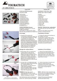
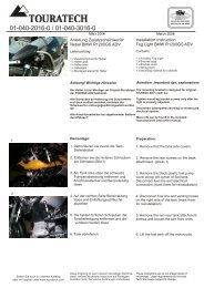
• If you would like <strong>to</strong> not only correct the Total Distance but reset it <strong>to</strong> zero,then press the E key for approximately one (1) second until the first field isblinking. Then press the “0” on the remote.4. Mounting the Attachment Plate4.1 Attention:Secure the attachment plate so that the mounted device in no interfereswith the operation of the vehicle. The attachment plate has an openingfor the connecting line that should be on the driver’s right hand side.4.2 Assembly:• Use the Flathead screw (m6) <strong>to</strong> attach the rubber cylinder <strong>to</strong> the attachmentplate. If necessary, insert the spring ring (m8). Select the appropriate borehole.• Place fastening clip around the handlebar – use the six-sided nut and springm6 <strong>to</strong> fasten.• Additional rubber cylinders or fastening clips can be ordered from <strong>Touratech</strong>.5. Mounting the Housing• Remove the 4 screws and take of housing lid.• The housing base then needs <strong>to</strong> be secured <strong>to</strong> the attachment plate with 4screws (m4) and 4 nuts (m4).• Screw the housing lid back in<strong>to</strong> place and cover the 4 screws with enclosedplastic covers.6. Mounting the Universal Wheel Sensor6.1 Assembly• Assemble the wheel sensor according <strong>to</strong> the drawing.• Don’t forget the spring ring.6.2 Attaching <strong>to</strong> Mo<strong>to</strong>rcycle.• Adhere the magnet as close as possible <strong>to</strong> the wheel hub. The yellow sidemust be on the outside and point of contact must be clean and grease-free.We recommend using contact adhesive for rough surfaces.• Attach the pre-mounted wheel sensor with the pipe clip (or similar) <strong>to</strong> thefork.• The wheel sensor must point directly <strong>to</strong> magnet and should be no more than1 mm from it. – Use the adjusting screw <strong>to</strong> set the distance <strong>to</strong> the magnetand set the alignment plate at required height.• The connecting lead must be securely attached <strong>to</strong> the fork leg with a cableclip. Ensure that the cable is laid without tension while the fork leg isextended and the handle is turned.6.2.1 If you wish <strong>to</strong> use your own magnet, make sure the south pole is pointingin the direction of the wheel sensor.7. Temperature Sensor7.1 Assembly• The temperature sensor is mounted in place of the oil drain screw. Thecable should be placed carefully. Place the plug very carefully.• The threads of the temperature sensor must be grounded <strong>to</strong> the Vehicle.• The temperature sensor can also be built in<strong>to</strong> the radia<strong>to</strong>r circula<strong>to</strong>r.• For R11XXGS, use oil plug adapter 015-0052 (M16X1.5)Page 15
IMO-100 R300 Opera<strong>to</strong>r’s Manualand Assembly Instructions8. The Electrical Connection8.1 Attention:Before beginning work on your vehicle disconnect the battery!• The IMO-100 R300 requires direct voltage between 9 and 17 volts!• Vehicles without a battery must have a rectifier, regula<strong>to</strong>r, and capaci<strong>to</strong>r.• <strong>Touratech</strong> offers these as accessories.8.2 General Information:• The IMO-100 R300 requires only two leads <strong>to</strong> connect <strong>to</strong> the wiring system -an earthing lead and a 12-volt supply voltage.• If the mo<strong>to</strong>rcycle is not being used, a supply voltage is not required. Thebuilt-in battery ensures that the clock continues <strong>to</strong> work for at least 5 years.• You can tap individual leads of the mo<strong>to</strong>rcycle cable harness with theenclosed cable tap (red “flexible parts”). It is important that no more than1qmm of the leads are clamped; the external lead diameter of the leadsbeing used should be less than 2.8mm.8.3 The Connection Plate: (Diagram only)8.4 Connecting <strong>to</strong> the Wiring System8.4.1 Preparation: The Leads included in the assembly materials will now beinsulated. Afterward, push a conducting terminal housing over the leadand pinch it with flat nosed pliers.Next screw the leads in<strong>to</strong> the screw terminals on the IMO’s terminalconnection block which are also included in the assembly materials. Thescrew terminals are placed on the stripped ends of the wires, thencrushed by the set-screw <strong>to</strong> become terminal ends.8.4.2 GND: Provide a clean connection <strong>to</strong> Vehicle either on the frame or onthe battery.8.4.3 + 12V: This is dependent on the precautionary voltage in the IMO-100R300. This lead must be switched over the ignition lock. Generally thisrefers <strong>to</strong> “lead 15” on the mo<strong>to</strong>rcycle.8.4.4 Wheel Sensor• This is where the 3-pronged screw terminal is plugged in<strong>to</strong> the wheelsensor.• If for assembly, you must disconnect the screw terminal from thelead, please notice the exact positioning of the leads so they can bereconnected properly. It is crucial that the order of the cables is thesame as the diagram; otherwise the sensor may be damaged.GreenWhiteBrown8.4.5 Remote ControlNow the 3-prong screw bracket from the remote control is plugged in.8.4.6 DZThis is the connection for the rev counter. Connect this line with the leadfrom the ignition, it is usually indicated with a “1 on the ignition coil. It isNOT the switched hot lead (wire 15) , it is the other lead (typically going<strong>to</strong> the points (or electronic ignition trigger). On the BMW R11xxGS it isthe small black wire <strong>to</strong> the coil. To locate the coil, follow a spark plugwire.8.4.7 MTPage 16
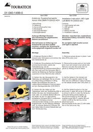
This is where the screw terminals from the engine temperature sensor isplugged in.• DZ and MT are connected through a screw bracket8.4.8 PCNo function (stays inactive)8.5 <strong>How</strong> <strong>to</strong> set the Rev Counter8.5.1 General:Because there are several different ignition systems on mo<strong>to</strong>rcycles, it isnecessary <strong>to</strong> adapt the rev counter <strong>to</strong> the voltage. The rev counteradaptation on the connection plate (identified by “R3”) prevents the IMO-100R from being damaged by a high interference voltage on the revcounter lead of your mo<strong>to</strong>rcycle.8.5.2 Attention:FOLLOW THESE DIRECTIONS PRECISELY TO PREVENT ANYDAMAGE TO YOUR VEHICLE!8.5.3 Setting:TURN THE POTENTIOMETER ON THE CONNECTION PLATECOUNTERCLOCKWISE AS FAR AS IT WILL GO BEFORE STARTINGYOUR MOTORCYCLE!Leave your mo<strong>to</strong>rcycle on and set your IMO-100 R300 on the BasicFunction. Leave the mo<strong>to</strong>r running and turn the potentiometer carefully<strong>to</strong> the right (clockwise), until the mo<strong>to</strong>r speed on the field “rev counter” onthe display is steady. Double check the rev counter for the entire speedrange of the mo<strong>to</strong>r. (Rev the engine and evaluate does the numbermake sense, or is it double or 1/2 of realistic RPMs)8.5.4 No Display?:If you do not see a display, then you have chosen the incorrect controllead. Reconnect the lead. BEFORE YOU STRAT YOURMOTORCYCLE AGAIN, TURN THE POTENTIOMETER AGAIN TO THELEFT (COUNTERCLOCKWISE)! Reset the potentiometer (point 7.5.3)8.5.5 Gluing in<strong>to</strong> Position:Glue the potentiometer in<strong>to</strong> the set position using Loctite, Nail polish,instant glue or a similar adhesive.8.6 Attaching of Connection Plate:You must attach the connection plate in a protected place, for example under thefuel tank. Damage can occur if water is allowed <strong>to</strong> reach the PC board.9 The Remote Control9.1 Assembly:The remote is fitted either <strong>to</strong> the handlebar next <strong>to</strong> the switch or with the adapter<strong>to</strong> the mirror. The distance <strong>to</strong> the handlebar can be determined using the suppliedspacers. (In case the rubber grips or switch element obstruct.) Plug the connec<strong>to</strong>r in<strong>to</strong>the connection plate of the IMO-100 R300.9.2 Usage• Rocker: the + and – key• Key: The “0” KeyColor of the lines connected <strong>to</strong> the screw terminal. Green, Red, BluePage 17
IMO-100 R300 Opera<strong>to</strong>r’s Manualand Assembly Instructions10 Trouble-shooting – When something doesn’t WorkDESCRIPTION OF ERROR:Lights function, but the display is inactiveThe Display is darkNo speed DisplaySpeed is reduced by half while driving or drops entirely <strong>to</strong>zeroDevice displays irregular speedsRev counter always indicates zeroRev counter displays irregular valuesTime entry is requested each time you turn on engineThe clock runs slow and loses timeCAUSE and FAULT ELIMINATIONThe Potentiometer is set incorrectly:• Please turn until the display is legible (refer <strong>to</strong> 1.1.3)The Potentiometer is set incorrectly:• Turn until the display is legible (refer <strong>to</strong> 1.1.3)The distance is <strong>to</strong>o great between wheel sensor andmagnet• Decrease the distance by regulating the adjustingscrew or adjusting the alignment plate (6.1 and 6.2)• Foreign magnet? The south pole must point <strong>to</strong> sensor(6.2.1)• Turn the sensor in the alignment plateThe distance is <strong>to</strong>o great between wheel sensor andmagnet• Decrease the distance by regulating the adjustingscrew or adjusting the alignment plate (6.1 and 6.2)• Foreign magnet? The south pole must point <strong>to</strong> sensor(6.2.1)Turn the sensor in the alignment plateInterference in electrical system• Connect earth connection directly <strong>to</strong>o battery• Use screened 5k sparkplugs• Check the ignition electrical system for interferenceRev counter adaptation <strong>to</strong> your ignition system is incorrect• Adapt rev counter as described in 8.5 with theassistance of the potentiometer on the connectionplate.Rev counter adaptation <strong>to</strong> your ignition system is incorrect• Adapt rev counter as described in 8.5 with theassistance of the potentiometer on the connectionplate. Please turn slowly <strong>to</strong> the right and do not in anyaccount, keep turning <strong>to</strong> the right!The Lithium Battery is empty• Send electronics in and renew batteryEvery time you enter the parameterization and make achange (e.g.) wheel size change), the seconds of the clockare reset <strong>to</strong> zero. That means you can lose up <strong>to</strong> 60seconds with each change.Page 18
11. Entering in the Vehicle Documents11.1 General:The IMO 100 R300 fulfills all requirements of the EU guidelines 75/443/EU andcan therefore be used in the form of a tachometer as a single instrument onmo<strong>to</strong>rcycles according <strong>to</strong> §57 StVZO.11.2 Characteristics:• The IMO 100 R300 is water proof and weather proof• It has illuminated display• Even after internal battery is emptied, the date (e.g. wheel size, km) ares<strong>to</strong>red a minimum of 100 years in a non-volatile, semiconduc<strong>to</strong>r memory.• Exact matching is achieved by entering wheel size (in mm).• To compensate for <strong>to</strong>lerances in the tires, the speed display has a lead of3%.• The IMO-100 R300 operates up <strong>to</strong> a speed of at last 500 km/hour• The wheel sensor operates wear free will a Hall-C effect.11.3 TUVAt delivery, the IMO is TUV approved.<strong>Touratech</strong> Mo<strong>to</strong>rcycle AccessoriesHerbert Schwarz and Jochen SchanzPO Box 1082D-78074 NiederschachF.R. GermanyTel: +49 (0) 77 28 / 92 79 - 0Fax: +49 (0) 77 28 / 92 79 -29E-mail: info@<strong>to</strong>uratech.dePage 19
IMO-100 R300 Opera<strong>to</strong>r’s Manualand Assembly Instructions12. EU-Name of Manufacturer<strong>Touratech</strong> AGAddress<strong>Touratech</strong> AGMo<strong>to</strong>rcycle AccessoriesPO Box 1082D-78074 NiederschachDetails for the aforementioned product:Product Name:ModelConstructed byRally Computer / Complete InstrumentIMO-100 R / IMO-100 R+ / IMO-100 R300AllIf the rules and regulations are explained <strong>to</strong> the general public.Safety EN 60950Classification III after VDE 0805EMC EN 50081-1EN 50081-2EN 50082-1EN 5008-2This product fulfills all requirements of the Low Voltage Directive 73/23/EEC and theEMC Directive 89/336/EEC.Dauchingen, 19.December 1995Page 20
13. Accessories:• Road Book Holder• Manual• Electrical• Road Book Lighting• Attachment plate <strong>to</strong> secure IMO-100 R300 <strong>to</strong> Road Book holder• Additional rubber parts for attachment• Additional large and small attachment clips• Wheel sensor holder for upside down fork (white power)• Rectifier – regula<strong>to</strong>r – capaci<strong>to</strong>r unit (see point 3.1, e.g. DR350 Sport)• Remote Control• Amp Uniformity Control14. Further Products from <strong>Touratech</strong>:• Akku-Lamp Chala 12 HD• Aluminum Touring box Zega 41 with 36 and 41 Liter capacity• Special holder for Aluminum box (universal attachment set)• Road Book Edi<strong>to</strong>r (software for the PC)• Special handlebar attachment for GPS Garmin 75/55/50• Quick lock for fuel line• Diverse bags for replacement hoses, etc.• Map bag• Foot rest BMW R100GS• Pre-build for the rebuild BMW R100 GS <strong>to</strong> disguise the original instrumentation andcontrolsUpon request, we would be delighted <strong>to</strong> send you an additional information on any of ourproducts.Page 21
IMO-100 R300 Opera<strong>to</strong>r’s Manualand Assembly Instructions15. NotesPage 22
16. Technical Data (Specifications)Dimensions120mm x 80mm x 34mmWeightApproximately 350g (without holder)Protective SystemIP 65 (waterproof)Operating Voltage9-15 voltsCurrent Consumption (ignition off) 0Current Consumption (ignition on)150 mAService Life of ClockApproximately 5 years (per battery)Deviation in Time+/- 2 seconds / day (only recognized every 10 seconds)DisplayLCD graphics displayIllumination of Display and KeysGreen LED lightingDeviation of battery life display +/- 2%Battery life display7 – 20 voltsDeviation of Outside Thermometer+/- 2° CDeviation of Oil Thermometer+/- 3° COutside Temperature Range-40°C <strong>to</strong> + 80° CTemperature Gauge Range Capabilities-40°C <strong>to</strong> + 160° CMaximum Speed500 km/hourVarious speeds and distances covered and deviations from these values depends on the size ofwheel that has been set.Subject <strong>to</strong> technical alterations in the course of progress.Page 23