Dampers for Centrifugal Fans - Greenheck
Dampers for Centrifugal Fans - Greenheck
Dampers for Centrifugal Fans - Greenheck

Create successful ePaper yourself
Turn your PDF publications into a flip-book with our unique Google optimized e-Paper software.
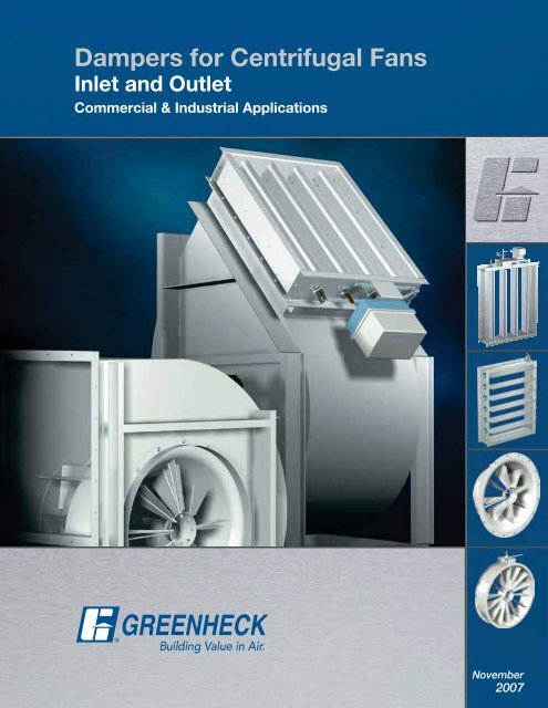
<strong>Dampers</strong> <strong>for</strong> <strong>Centrifugal</strong> <strong>Fans</strong><br />
Inlet and Outlet<br />
Commercial & Industrial Applications<br />
November<br />
2007
GREENHECK CENTRIFUGAL FANS WITH DAMPERS FOR<br />
COMMERCIAL AND INDUSTRIAL APPLICATIONS ARE AN<br />
UNBEATABLE COMBINATION<br />
<strong>Dampers</strong> used in conjunction with centrifugal fans provide a simple, reliable<br />
and cost effective means <strong>for</strong> controlling air systems. Complimenting its<br />
centrifugal fan line, <strong>Greenheck</strong> has an extensive offering of control and<br />
isolation dampers <strong>for</strong> commercial and industrial applications.<br />
<br />
the maximum air velocity.<br />
<br />
<br />
<br />
reduce system effect losses.<br />
<br />
means versatility and flexibility in being able to select the best<br />
combination <strong>for</strong> system requirements.<br />
<br />
tuning counter balances; adjustments <strong>for</strong> linkage and blade<br />
operation; setting actuator limits.<br />
<br />
unit so there is no field mounting required.<br />
The <strong>Greenheck</strong> “Total <strong>Centrifugal</strong> Fan Package”<br />
<strong>Dampers</strong> are just one component of the <strong>Greenheck</strong><br />
centrifugal fan package. Completely assembled fan<br />
and option packages are available including your<br />
<br />
<br />
<br />
<br />
<br />
<br />
<br />
<br />
(Sure-Aire)<br />
The package includes long life bearings and a<br />
complete vibration analysis.<br />
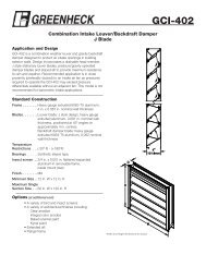
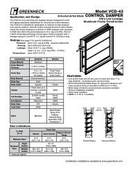
Outlet Volume Control <strong>Dampers</strong><br />
are commonly used in variable air volume<br />
systems. Blades are mounted perpendicular to<br />
fan shaft <strong>for</strong> even <strong>for</strong>ce loading on the blades<br />
and to reduce pressure losses.<br />
2
Backdraft <strong>Dampers</strong><br />
prevent reverse airflow<br />
through the system.<br />
Recommended to<br />
be used on fan<br />
Classes I, II, III only.<br />
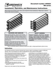
Inlet Box <strong>Dampers</strong><br />
are used when applications<br />
require inlet boxes.<br />
Inlet box dampers have<br />
per<strong>for</strong>mance characteristics<br />
similar to inlet vane dampers.<br />
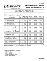
Nested Inlet Vane <strong>Dampers</strong><br />
have linkages incorporated into the housing<br />
of the fan. Used in variable air volume<br />
applications with space constraints.<br />
External Inlet Vane <strong>Dampers</strong><br />
are mounted in the airstream or directly to the<br />
fan housing leaving linkages accessible <strong>for</strong><br />
maintenance. Often used <strong>for</strong> variable air volume<br />
retrofit applications.<br />
3
Outlet <strong>Dampers</strong><br />
OUTLET DAMPERS<br />
<br />
the need <strong>for</strong> actuators differentiates these models.<br />
BACKDRAFT DAMPERS<br />
allow air to pass in one direction<br />
and restrict flow in the opposite<br />
direction. The dampers have<br />
gravity actuation with a counter<br />
weight and linkage assembly.<br />
This is an inexpensive means of<br />
keeping air from flowing back<br />
through a system. Initial and<br />
required maintenance costs<br />
are low.<br />
OUTLET VOLUME<br />
CONTROL DAMPERS<br />
regulate the airflow by<br />
modulating the damper blades.<br />
Actuators may be manual,<br />
electric or pneumatic and are<br />
mounted out of the airstream.<br />
Control dampers are specially<br />
designed so blades are all<br />
perpendicular to the fan<br />
<br />
pressure losses and distributes<br />
the stresses associated with<br />
velocity pressures evenly. Both<br />
parallel and opposed blade<br />
styles are available.<br />
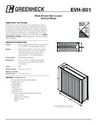
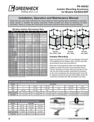
HOW OUTLET DAMPERS AFFECT<br />
FAN PERFORMANCE<br />
<br />
static pressure changes with the resistance produced by<br />
modulating or closing the damper blades.<br />
The figure to the right illustrates the per<strong>for</strong>mance<br />
characteristics of a centrifugal fan with different damper<br />
blade positions. Point A shows the per<strong>for</strong>mance when the<br />
damper is in an open position. Point B illustrates the shift<br />
<br />
each blade position there will be a new system curve and<br />
operating point. The original static pressure (Ps) and brake<br />
horsepower (Bhp) curves remain unchanged.<br />
Bhp Curve<br />
Fan Curve (Ps)<br />
B<br />
A<br />
PARALLEL OR OPPOSED?<br />
Control dampers are offered with either parallel<br />
<br />
<br />
per<strong>for</strong>mance plus a change in air velocity profile.<br />
<br />
range of 75% to 100% wide open volume due to the<br />
amount of control arm swing required to modulate the<br />
blades. Parallel blades are used when greater control is<br />
required near the top end of the volume operating range<br />
or <strong>for</strong> systems requiring two position (fully open or fully<br />
closed) operation. Parallel blades should not be used<br />
upstream of critical components due to uneven airflow.<br />
System Curves<br />
Volumetric Flow (CFM)<br />
<strong>Centrifugal</strong> Fan with Outlet Damper<br />
<br />
the entire operating range. Opposed blades are used<br />
<strong>for</strong> applications where it is necessary to maintain even<br />
distribution of air downstream from the damper. This<br />
style of blade is the best selection <strong>for</strong> ducted outlets.<br />
Parallel Blade<br />
Opposed Blade<br />
Top View of Blade Action Styles<br />
4
Inlet <strong>Dampers</strong><br />
INLET DAMPERS<br />
Inlet dampers include nested inlet vane, external inlet vane and inlet box dampers. These models save power<br />
by reducing Bhp requirements and should be considered when the fan operates <strong>for</strong> long periods at reduced<br />
capacities.<br />
NESTED INLET VANE<br />
DAMPERS<br />
are primarily used in non-ducted<br />
applications with space<br />
constraints. The vanes and<br />
linkages are located inside<br />
the fan housing with the<br />
actuator mounted outside.<br />
Recommended <strong>for</strong> clean air<br />
applications only.<br />
EXTERNAL INLET VANE<br />
DAMPERS<br />
are intended <strong>for</strong> ducted<br />
applications and those with<br />
higher pressures and velocities.<br />
These dampers are mounted in<br />
the airstream or directly to the<br />
fan housing. Advantages are<br />
accessibility to the linkages <strong>for</strong><br />
maintenance and flexibility in<br />
mounting location.<br />
INLET BOX DAMPERS<br />
are used in clean air<br />
applications where an inlet box<br />
<br />
supplied with parallel blades<br />
<strong>for</strong> per<strong>for</strong>mance characteristics<br />
similar to inlet vane dampers.<br />
Actuators are mounted outside<br />
of the airstream.<br />
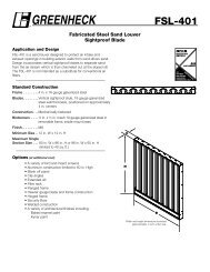
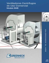
HOW INLET DAMPERS IMPACT<br />
FAN PERFORMANCE<br />
Inlet dampers start a pre-spin on air entering into the fan.<br />
The pre-spin placed on the entering airflow will be in the<br />
same direction as the wheel rotation. This does not allow<br />
the wheel to develop its full per<strong>for</strong>mance profile, limiting<br />
the amount of air flowing through the fan. This pre-spin<br />
also reduces the energy requirements of the fan and the<br />
overall effect is very similar to reducing the speed on an<br />
undampered fan.<br />
<strong>Centrifugal</strong> fans with inlet vane dampers have different<br />
operating points depending on the blade position of the<br />
damper. As an inlet damper actuates, open or closed,<br />
new operating points are found on the system curve.<br />
See the figure to the right. Different operating points are<br />
<br />
<br />
and brake horsepower curve. These points show that<br />
by closing an inlet damper, airflow is reduced and less<br />
energy is required by the fan.<br />
Ps/Bhp<br />
Fan Curves (Ps)<br />
Bhp Curves<br />
E<br />
System Curves<br />
Volumetric Flow (CFM)<br />
D<br />
C<br />
<strong>Centrifugal</strong> Fan with Inlet Damper<br />
5
Damper Selection<br />
INLET VANE DAMPER<br />
<br />
functioning of the damper and fan combination. Damper rotations are viewed from the air inlet side of the fan, and<br />
<br />
air inlet side, and will be the opposite of the damper. If the wrong rotation is selected, there will be a moderate<br />
pressure increase, Bhp will increase significantly, and pulsations may occur.<br />
The graphs below show the effects that blade actuation has on static pressure, Bhp, and cfm with inlet vane<br />
<br />
Static Pressure vs. Wide Open Volume<br />
Brake Horsepower vs. Wide Open Volume<br />
100<br />
100<br />
Without Vanes<br />
90<br />
90<br />
80<br />
80<br />
75% Open<br />
100% Open<br />
% Peak Static Pressure<br />
70<br />
60<br />
50<br />
40<br />
30<br />
50% Open<br />
75% Open<br />
Without Vanes<br />
100% Open<br />
% Peak Brake Horsepower<br />
70<br />
60<br />
50<br />
40<br />
30<br />
25% Open<br />
50% Open<br />
25% Open<br />
0% Open<br />
20<br />
10<br />
0<br />
0 10 20 30 40 50 60 70 80 90 100<br />
% Wide Open Volume<br />
20<br />
10<br />
0<br />
0 10 20 30 40 50 60 70 80 90 100<br />
% Wide Open Volume<br />
CLASS<br />
MINIMUM RECOMMENDED ACTUATOR TORQUE FOR INLET VANES (in.-lbs.)<br />
<strong>for</strong> SINGLE WIDTH FANS (Model BISW and AFSW)*<br />
<br />
*Consult factory <strong>for</strong> Class IV applications<br />
DAMPER SELECTION GUIDE<br />
FAN SIZE<br />
12 13 15 16 18 20 22 24 27 30 33 36 40 44 49 54 60 66 73<br />
I 26 30 33 38 47 57 68 110 130 140 160 180 270 320 370 430 500 600 700<br />
II 38 43 49 58 73 88 110 160 180 200 230 260 420 490 580 680 800 960 1100<br />
III 54 63 72 86 110 130 160 220 260 280 330 380 620 740 880 1000 1200 1500 1700<br />
The following table is useful in determining the type of damper that is appropriate <strong>for</strong> a given application.<br />
Additional considerations are to used only outlet dampers <br />
when Variable Air Volumes (VAV) are required, either outlet volume control dampers or inlet dampers are the correct<br />
choice.<br />
SELECTION<br />
FACTORS<br />
Control<br />
<br />
Airflow<br />
downstream<br />
from fan<br />
Cost<br />
<br />
Horsepower<br />
Backdraft<br />
Damper<br />
Prevents<br />
backflow<br />
Minor<br />
downward<br />
direction<br />
Low start-up and<br />
maintenance costs<br />
OUTLET DAMPERS<br />
Parallel Blade<br />
Outlet Volume<br />
Control Damper<br />
Good control from<br />
75% to 100% wide<br />
open volume<br />
*Prevents backflow<br />
Directs air<br />
to one side<br />
Opposed Blade<br />
Outlet Volume<br />
Control Damper<br />
Best when used to<br />
control the entire<br />
operation range<br />
Distributes<br />
air evenly<br />
Higher initial cost than<br />
Backdraft dampers<br />
Unchanged from the original undampered<br />
Bhp curve as blades modulate<br />
<br />
Vane Damper<br />
Increased costs<br />
over nested<br />
inlet damper<br />
INLET DAMPERS<br />
<br />
Vane Damper<br />
Used in variable air volume<br />
systems, provides control<br />
the entire operating range<br />
Pre-spins air be<strong>for</strong>e entering<br />
fan, no affect on airflow<br />
downstream of the fan<br />
Least expensive<br />
inlet dampers<br />
Inlet Box<br />
Damper<br />
Highest<br />
initial cost<br />
Decreased Bhp requirements with airflow<br />
(cfm) reduction provides energy savings<br />
6
MATCHING DAMPERS WITH FANS<br />
Damper<br />
Types<br />
<br />
Vane Damper<br />
<br />
Vane Damper<br />
Inlet Box<br />
Damper<br />
Backdraft<br />
Damper<br />
Outlet Volume<br />
Control Damper<br />
Single Width<br />
BISW/AFSW<br />
Double Width<br />
BIDW/AFDW<br />
Plenum <strong>Fans</strong><br />
QEP<br />
FAN MODELS<br />
Utility <strong>Fans</strong><br />
SWB<br />
Industrial<br />
Process<br />
(IPA Only)<br />
Inline<br />
<strong>Centrifugal</strong><br />
TCB, TCF<br />
<br />
<br />
<br />
<br />
<br />
<br />
more in<strong>for</strong>mation.<br />
CONSTRUCTION<br />
Damper<br />
Types<br />
<br />
Vane Damper<br />
<br />
Vane Damper<br />
Material<br />
Temperature<br />
(Maximum)<br />
Ps Actuators Bearings<br />
Std Opt Std Opt Max Std Opt Std<br />
Steel<br />
Steel<br />
<br />
SS<br />
<br />
93ºC<br />
<br />
93ºC<br />
— 8.5<br />
— 8.5<br />
Manual<br />
Quadrant<br />
Manual<br />
Quadrant<br />
<br />
Pneumatic<br />
<br />
<br />
Pneumatic<br />
<br />
SS Sleeve<br />
SS Sleeve<br />
Backdraft<br />
Damper<br />
Galv. Steel<br />
Aluminum<br />
304 SS<br />
<br />
82ºC<br />
<br />
122ºC<br />
20 <br />
Outlet Volume<br />
Control<br />
Galv. Steel<br />
304 SS<br />
<br />
93ºC<br />
<br />
538ºC<br />
35<br />
Manual<br />
Quadrant<br />
<br />
Pneumatic<br />
<br />
SS Sleeve<br />
Due to continuing product development, maximum temperatures and static pressures may change. Inlet box dampers<br />
have the same standard and optional construction features as outlet volume control dampers.<br />
<br />
Per<strong>for</strong>mance Coatings <strong>for</strong> Ventilation Products, <strong>for</strong> a complete listing of coatings and a relative resistance chart.<br />
STANDARD BEARINGS<br />
ACTUATOR OPTIONS<br />
STAINLESS STEEL<br />
SLEEVE<br />
MANUAL<br />
QUADRANT<br />
ELECTRIC<br />
TWO POSITION OR<br />
MODULATING<br />
POWER OPEN SPRING<br />
RETURN CLOSED<br />
BALL<br />
BEARING<br />
MANUAL<br />
WORM GEAR<br />
PNEUMATIC WITH<br />
MANUAL OVERRIDE<br />
7
Checklist <strong>for</strong> <strong>Dampers</strong> and Actuators<br />
DAMPERS<br />
1) Outlet Damper Types:<br />
Backdraft<br />
Control Volume - Parallel Blades<br />
Control Volume - Opposed Blades<br />
Inlet Damper Types:<br />
<br />
<br />
Inlet Box Damper<br />
2) Construction Options:<br />
Actuators (see list <strong>for</strong> more detail)<br />
Material (blade & frame)<br />
3) Protective Coatings<br />
ACTUATORS<br />
1) Type:<br />
<br />
Pneumatic<br />
Manual<br />
2) Operation:<br />
Spring-return power open/power<br />
closed (electric)<br />
Double acting (pneumatic)<br />
3) Operating Mode:<br />
Two-position<br />
Modulating<br />
4) Fail Direction<br />
5) Power Supply<br />
6) Control Signal<br />
7) NEMA Enclosure<br />
Important Note:<br />
<br />
detail on a particular product or technical in<strong>for</strong>mation, please refer to the <strong>Greenheck</strong> <strong>Dampers</strong><br />
and Louvers binder or our website at www.greenheck.com <br />
current <strong>Greenheck</strong> product literature. If you require further assistance or in<strong>for</strong>mation please<br />
contact your local <strong>Greenheck</strong> rep or refer to our website to find your nearest <strong>Greenheck</strong> rep.<br />
Building Value in Air<br />
<strong>Greenheck</strong> delivers value<br />
to mechanical engineers by<br />
helping them solve virtually<br />
any air quality challenges<br />
their clients face with a<br />
comprehensive selection of<br />
<br />
top quality, innovative airrelated<br />
equipment. We offer<br />
extra value to contractors<br />
by providing easy-to-install,<br />
competitively priced, reliable<br />
products that arrive on time.<br />
And building owners and<br />
occupants value the energy<br />
efficiency, low maintenance<br />
and quiet dependable operation<br />
they experience long after the<br />
construction project ends.<br />
<strong>Greenheck</strong> warrants this equipment to be free from defects in material and workmanship <strong>for</strong> a period<br />
of one year from the purchase date. Any units or parts which prove defective during the warranty<br />
period will be replaced at our option when returned to our factory, transportation prepaid. Motors are<br />
warranted by the motor manufacturer <strong>for</strong> a period of one year. Should motors furnished by <strong>Greenheck</strong><br />
prove defective during this period, they should be returned to the nearest authorized motor service<br />
station. <strong>Greenheck</strong> will not be responsible <strong>for</strong> any removal or installation costs.<br />
As a result of our commitment to continuous improvement, <strong>Greenheck</strong> reserves the right to change<br />
specifications without notice.<br />
Prepared to Support<br />
Green Building Ef<strong>for</strong>ts<br />
<br />
<strong>Dampers</strong> <strong>for</strong> <strong>Centrifugal</strong> <strong>Fans</strong>, Rev. 2, November 2007 SN<br />
Copyright © 2007 <strong>Greenheck</strong> Fan Corp.