dSPACE Prototyping Systems
dSPACE Prototyping Systems
dSPACE Prototyping Systems

Create successful ePaper yourself
Turn your PDF publications into a flip-book with our unique Google optimized e-Paper software.
Rapid Control <strong>Prototyping</strong> /<strong>dSPACE</strong> <strong>Prototyping</strong> <strong>Systems</strong><br />
<strong>dSPACE</strong> <strong>Prototyping</strong> <strong>Systems</strong><br />
Accelerated function prototyping for controller development<br />
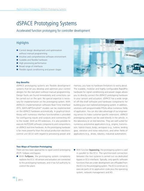
Highlights<br />
• Control design development and optimization<br />
without manual programming<br />
• Intuitive and comprehensive software environment<br />
• Scalable and flexible hardware<br />
• High processing performance<br />
• Broad range of interfaces<br />
• Flexible signal conditioning and power stages<br />
Key Benefits<br />
<strong>dSPACE</strong> prototyping systems are flexible development<br />
systems that let you develop and optimize your control<br />
designs for the real plant without manual programming.<br />
Design faults are found immediately and corrections can<br />
be carried out on the spot. No special expertise is necessary<br />
for implementation on the prototyping system. With<br />
<strong>dSPACE</strong>’s implementation software Real-Time Interface<br />
(RTI), MATLAB ® /Simulink ® models can be implemented<br />
on the <strong>dSPACE</strong> hardware automatically. A graphical block<br />
library with numerous interface functionalities is provided<br />
for configuring inputs and outputs and connecting I/O<br />
to the model. With an RTI extension, it is also possible to<br />
execute AUTOSAR software components and compositions<br />
on <strong>dSPACE</strong> real-time hardware. As the prototyping hardware<br />
is far more powerful than the actual production electronic<br />
control unit (ECU) with regard to processing power and<br />
memory, you have no hardware limitations to worry about.<br />
The scalable, modular and highly configurable RapidPro<br />
hardware for signal conditioning and power stages allows<br />
you to directly connect the <strong>dSPACE</strong> prototyping hardware<br />
to your sensors and actuators. <strong>dSPACE</strong> has a wide range<br />
of off-the-shelf software and hardware components for<br />
building your own tailored prototyping system. In addition,<br />
solutions with programmable FPGAs allow numerous fields<br />
of application. You can also take advantage of our engineering<br />
service to make customer-specific extensions. <strong>dSPACE</strong><br />
prototyping systems can be used directly in the vehicle, in<br />
the laboratory or on test benches. They are well suited for<br />
numerous automotive applications (e.g., engine, transmission,<br />
hybrid chassis, body), aerospace (e.g., turbine, landing<br />
gear, vibration and noise reduction), and other fields of<br />
applications (e.g., drives, robotics, industrial automation).<br />
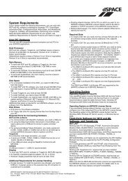
Two Ways of Function <strong>Prototyping</strong><br />
There are two basic approaches to rapid control prototyping<br />
(RCP): fullpass and by pass.<br />
• With fullpass, the prototyping system completely<br />
replaces the ECU. All sensors and actuators are connected<br />
to this prototyping hardware, and it has full authority to<br />
control the plant.<br />
• With function bypassing, the prototyping system is used<br />
in parallel to the ECU. The synchronized connection<br />
between the two systems is carried out via dedicated<br />
bypass or ECU interfaces. Typically, only specific software<br />
functions that are under development are offloaded from<br />
the ECU to the prototyping system. The ECU continues to<br />
execute parts of its application code plus the operating<br />
system, network management and I/O.<br />
48<br />
2011
Rapid Control <strong>Prototyping</strong> / <strong>dSPACE</strong> <strong>Prototyping</strong> <strong>Systems</strong><br />
Fullpassing<br />
Introduction<br />
Using a <strong>Prototyping</strong> System as a Flexible<br />
Experimental ECU<br />
If a new ECU or a new set of control functions has to be<br />
developed from scratch, quick trials have to be run at an<br />
early stage to verify the correctness of the control strategy.<br />
Tests in a vehicle or on a test bench therefore have to be<br />
carried out even before the new ECU hardware becomes<br />
available. Producing an application-specific prototype ECU<br />
for this purpose, e.g. by means of a modified production<br />
ECU, would be expensive, time-consuming and inflexible.<br />
Instead, developers can use a powerful off-the-shelf prototyping<br />
system which acts as an experimental ECU, but which<br />
has many advantages compared to other solutions. The<br />
<strong>dSPACE</strong> prototyping system allows developers to concentrate<br />
completely on the new function design without having to<br />
worry about computing power and memory – the system<br />
offers plenty of both, ensuring maximum flexibility. Unlike<br />
a production-type ECU, programming a <strong>dSPACE</strong> prototyping<br />
system is easy. This makes it particularly convenient to<br />
change ECU function designs without having to do manual<br />
programming. Function prototyping begins with graphical<br />
descriptions of control functions, created and tested in a<br />
modeling and simulation environment such as MATLAB ® /<br />
Simulink ® /Stateflow ® . Changes to the function model can<br />
therefore be carried out quickly and conveniently, and<br />
downloaded to the prototyping system via automatic code<br />
generation at a click. This procedure provides the shortest<br />
possible iteration times. I/O interfaces can be configured<br />
and easily integrated into the function model by means of<br />
a comprehensive graphical I/O block library which is part of<br />
the RTI software (p. 126). Parameters of the control function<br />
can be changed and signals can be captured on-the-fly by<br />
means of or ControlDesk ® Next Generation (p. 160).<br />
Application Fields<br />
System Architecture<br />
Rapid Control <strong>Prototyping</strong><br />
<strong>dSPACE</strong> <strong>Prototyping</strong> <strong>Systems</strong> 1)<br />
ECU Autocoding<br />
I/O<br />
HIL Testing<br />
<strong>Prototyping</strong> of new functions, I/O<br />
Fullpassing: the prototyping system completely replaces the ECU.<br />
Engineering<br />
Connecting Sensors and Actuators<br />
Signal conditioning and power stages are decisive for the<br />
optimal connection of sensors and actuators to prototyping<br />
systems. To cover today’s variety of sensors and actuators,<br />
<strong>dSPACE</strong> offers the RapidPro hardware (p. 462) as an<br />
optional extension to a <strong>dSPACE</strong> prototyping system. The very<br />
compact, robust and modular RapidPro hardware consists<br />
of ready-made and easy-to-insert hardware- and softwareconfigurable<br />
interface modules for the highest degree of<br />
flexibility. Changes in the sensor-actuator setup are no longer<br />
a risk for your development project, home-made solutions<br />
are no longer necessary.<br />
Software<br />
1)<br />
For information on possible product combinations, please contact <strong>dSPACE</strong>.<br />
2011<br />
49<br />
Hardware
Rapid Control <strong>Prototyping</strong> /<strong>dSPACE</strong> <strong>Prototyping</strong> <strong>Systems</strong><br />
Comparison: <strong>dSPACE</strong> <strong>Prototyping</strong> System versus ECU<br />
<strong>dSPACE</strong> <strong>Prototyping</strong> System<br />
Processor Scalable, floating-point, high processing power Optimized (i.e. limited) for target application; low<br />
processing power<br />
Memory Large Limited<br />
I/O Flexible, modular, configurable Application-specific, fixed<br />
Signal conditioning and power stages Flexible, modular, configurable via RapidPro Hardware (basic Application-specific, fixed<br />
signal conditioning also integrated in MicroAutoBox 1) )<br />
Size All sizes from small to fairly large, depending on use scenario Small<br />
Programming Graphical, convenient, automatic implementation Difficult, manual<br />
Host access Dedicated high-speed interfaces ECU-specific (e.g. CAN)<br />
ECU<br />
Bypassing<br />
Integrating New Functions in Existing Controllers<br />
In contrast to fullpass applications, where the ECU is completely<br />
replaced by the prototyping system, with the external<br />
bypass approach only individual parts of the algorithms are<br />
shifted to the prototyping system. Sensors and actuators are<br />
interfaced via the existing harness of the ECU and only the<br />
I/O which is additionally required needs to be connected to<br />
the prototyping system. The bypass method is an efficient<br />
approach, especially to developing new functions and optimizing<br />
existing controller strategies. The original controller<br />
executes all functions that remain unchanged, while new<br />
algorithms are executed on the prototyping hardware.<br />
Using the external bypass approach gives you great flexibility<br />
during the design phase, since you have almost no resource<br />
constraints in RAM, ROM, processor performance, or I/O<br />
channels. Real-time behavior is guaranteed even with complex<br />
bypass functions. In addition, the fast autonomous booting<br />
of the prototyping systems allow you to validate the behavior<br />
of the new function in realistic scenarios, for example,<br />
during test drives.<br />
1)<br />
The MicroAutoBox II 1401/1507 does not offer standard I/O or signal conditioning but focuses on the bus and interface features (see p. 446).<br />
50<br />
2011
Rapid Control <strong>Prototyping</strong> / <strong>dSPACE</strong> <strong>Prototyping</strong> <strong>Systems</strong><br />
Software<br />
Application Fields<br />
System Architecture<br />
Engineering<br />
Introduction<br />
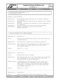
External Bypass Methods and Interfaces<br />
To divert the flow of data from the ECU to the prototyping<br />
system and back, <strong>dSPACE</strong> supports several methods and<br />
interfaces:<br />
• DPMEM Plug-On Device (POD)<br />
• On-Chip Debug Interface (e.g., JTAG/Nexus,<br />
JTAG/OCDS, NBD, AUD)<br />
• XCP on CAN<br />
• XCP on Ethernet (UDP/IP)<br />
• XCP on FlexRay<br />
• CCP<br />
<strong>dSPACE</strong> <strong>Prototyping</strong> <strong>Systems</strong> 1)<br />
Additional I/O<br />
Rapid Control <strong>Prototyping</strong><br />
<strong>Prototyping</strong> of new functions,<br />
additional I/O<br />
Existing functions and I/O<br />
• CCP<br />
• XCP on CAN<br />
• XCP on Ethernet<br />
• XCP on FlexRay<br />
ECU Interfaces<br />
• On-chip debug<br />
interfaces<br />
• DPMEM PODs<br />
ECU Autocoding<br />
Existing ECU<br />
I/O<br />
HIL Testing<br />
External bypassing: New functions run on the prototyping system, while unchanged algorithms stay on the ECU.<br />
1)<br />
For information on possible product combinations, please contact <strong>dSPACE</strong>.<br />
2011<br />
51<br />
Hardware
Rapid Control <strong>Prototyping</strong> /<strong>dSPACE</strong> <strong>Prototyping</strong> <strong>Systems</strong><br />
Address-Based Bypassing<br />
Address-based bypassing is one method for off-loading<br />
specific sections of ECU code to a prototyping system for<br />
function optimization and development. It can be applied<br />
in combination with a dual-port memory (DPMEM) or an<br />
on-chip debug interface. The method involves integrating<br />
customer-specific code patches into the ECU code. If the<br />
input and output variables of functions change, the ECU<br />
code typically also needs to be modified. Address-based<br />
bypassing allows very fast execution times and minimum<br />
latencies in data transmission. For example, using a <strong>dSPACE</strong><br />
address-based bypass system with a DPMEM plug-on device<br />
(POD), the latency for 20 bytes to be sent from the ECU to<br />
the prototyping system and back again is only 2 x 8.5 µs.<br />
Service-Based Bypassing<br />
Normally, preparation of the ECU code for bypassing is<br />
carried out only once by the ECU supplier. With servicebased<br />
bypassing as supported by <strong>dSPACE</strong>, more than 100<br />
functions in the ECU code can be prepared for bypassing<br />
by means of service calls (bypass hooks). Afterwards, there<br />
is no need to modify the ECU code again. Service calls in<br />
the ECU code can be described in an ECU description file<br />
(A2L file) and evaluated by the RTI Bypass Blockset, so you<br />
can flexibly select the functions to be bypassed and the<br />
ECU variables to be read and written in the modeling environment.<br />
Moreover, service-based bypassing is a generic<br />
solution which can be applied independently of the ECU<br />
interface, the processor type, and coding methods. <strong>dSPACE</strong><br />
provides ECU services for DPMEM PODs and the DCI-GSI1<br />
as well as for XCP, the Universal Measurement and Calibration<br />
Protocol. The services can be used for measurement,<br />
calibration, ECU flash programming, and bypassing. They<br />
are available in C code and have to be compiled and linked<br />
to the ECU code only once. In addition, <strong>dSPACE</strong> provides<br />
an example C-code implementation for the synchronization<br />
of data using the CCP download mechanism in connection<br />
with bypassing via an existing CCP service in the ECU.<br />
Dual-Port Memory (DPMEM)<br />
A dual-port memory allows read and write access by two systems<br />
(processors) independently of one another, so that they<br />
can exchange data. Each of the two ports has its own address,<br />
control, and data channels. DPMEMs are used in bypassing to<br />
transmit data between the ECU and the prototyping system<br />
via their shared memory with the smallest possible latencies.<br />
Plug-on Device (POD)<br />
Plug-on devices are additional components mounted on an<br />
ECU to connect it to the prototyping hardware (for example,<br />
the DS4121 ECU Interface Board). PODs contain a dual-port<br />
memory (DPMEM) which is connected directly to the address<br />
and data bus of the microcontroller, and signal-conditioning<br />
tailored to the specific ECU.<br />
Universal Measurement and Calibration Protocol (XCP)<br />
The XCP protocol is the successor to the CAN Calibration<br />
Protocol CCP and standardized by ASAM (www.asam.net).<br />
XCP technology is independent of the transport layer, so<br />
XCP can be used with different physical layers such as CAN,<br />
FlexRay or Ethernet. <strong>dSPACE</strong> provides an XCP service implementation<br />
that is fully compatible with the ASAM standard<br />
for various processor platforms. Apart from basic features<br />
such as measurement, calibration, page switching, and ECU<br />
flash programming, the <strong>dSPACE</strong> XCP implementation also<br />
supports function bypassing.<br />
52<br />
2011
Rapid Control <strong>Prototyping</strong> / <strong>dSPACE</strong> <strong>Prototyping</strong> <strong>Systems</strong><br />
Introduction<br />
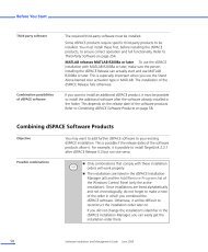
Function Bypassing Without Sampling Step Delay<br />
Rapid Control <strong>Prototyping</strong><br />
Application Fields<br />
System Architecture<br />
Implementation example (1) of function bypassing using XCP on CAN.<br />
Function Bypassing With Sampling Step Delay<br />
Software<br />
ECU Autocoding<br />
Engineering<br />
HIL Testing<br />
Implementation example (2) of function bypassing using XCP on CAN.<br />
2011<br />
53<br />
Hardware
Rapid Control <strong>Prototyping</strong> /<strong>dSPACE</strong> <strong>Prototyping</strong> <strong>Systems</strong><br />
Early Focus on the Production ECU<br />
Streamlining the Process<br />
Developing and optimizing new control functions with<br />
<strong>dSPACE</strong> prototyping systems speeds up the whole ECU<br />
development process by giving you early feedback if a control<br />
function is ready for or worth taking into production.<br />
To streamline the process from prototyping to production,<br />
<strong>dSPACE</strong> prototyping systems allow you to think ahead and<br />
take production aspects into account while still at an early<br />
stage of development.<br />
Guidance During Modeling<br />
Not all blocks provided by Simulink and not all modeling<br />
styles are suited for efficient and reliable production code<br />
generation. Established modeling guidelines 1) are ideal for<br />
an early focus on the production code. Another option is<br />
the dedicated license-free TargetLink ® Blockset Stand-Alone<br />
(p. 227), which offers RCP users a subset of Simulink blocks<br />
that are highly suitable for production code generation<br />
without implementation data having to be entered at the<br />
prototyping phase. If you follow guidelines and use the<br />
TargetLink Blockset, you can use the same models for rapid<br />
control prototyping and the generation of highly efficient<br />
production code.<br />
Validation of Production Code on <strong>dSPACE</strong><br />
Proto typing <strong>Systems</strong><br />
In some cases it is useful to verify the production code<br />
on the prototyping system. For that purpose, TargetLink’s<br />
Stand-Alone Model Manager can be used to generate a<br />
stand-alone S-function for Simulink that runs the TargetLink<br />
generated production code in a non-TargetLink environment.<br />
From there it is possible to generate a real-time application<br />
using Real-Time Interface (RTI) (p. 126) from <strong>dSPACE</strong> even<br />
without having TargetLink installed.<br />
1)<br />
Please contact <strong>dSPACE</strong> for more information.<br />
54<br />
2011
Rapid Control <strong>Prototyping</strong> / <strong>dSPACE</strong> <strong>Prototyping</strong> <strong>Systems</strong><br />
Software<br />
Engineering<br />
Introduction<br />
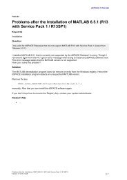
Rapid Control <strong>Prototyping</strong> and ECU Calibration<br />
More and more often, control engineers are considering production<br />
issues when they work on rapid control prototyping<br />
projects. A well-established approach for this is to include<br />
modelling style guides during control design and to define<br />
distinct labels for measurement and calibration variables in<br />
terms of Simulink ® objects in the MATLAB ® workspace. This<br />
way you can use the same controller models and the same<br />
labels throughout the development phases.<br />
With ControlDesk ® Next Generation (p.160) for prototyping<br />
and ECU calibration you can easily exchange and compare<br />
calibration and measurement data from the different<br />
development stages. Data sets in ControlDesk can also be<br />
fed back into the MATLAB/Simulink environment. In addition,<br />
the same instrument panels (layouts) can be used without<br />
modification for prototyping and ECU calibration.<br />
Application Fields<br />
System Architecture<br />
<strong>dSPACE</strong><br />
<strong>Prototyping</strong> system<br />
Real-Time Workshop ® TargetLink ®<br />
Stand-Alone<br />
Blockset<br />
Same controller model for prototyping<br />
and for production code<br />
Production ECU<br />
TargetLink<br />
Rapid Control <strong>Prototyping</strong><br />
TRC<br />
• Model variables defined in the MATLAB ®<br />
workspace as Simulink ® objects<br />
• Same labels in TRC and A2L variable<br />
description files<br />
A2L<br />
ECU Autocoding<br />
ControlDesk ® Next Generation<br />
Measurement<br />
files<br />
Data<br />
sets<br />
• Exchange and compare calibration<br />
and measurement data<br />
• Same instrument panels for prototyping<br />
and ECU calibration<br />
HIL Testing<br />
2011<br />
55<br />
Hardware
Rapid Control <strong>Prototyping</strong> /<strong>dSPACE</strong> <strong>Prototyping</strong> <strong>Systems</strong><br />
AUTOSAR in Rapid Control <strong>Prototyping</strong><br />
Rapid control prototyping Benefits AUTOSAR<br />
Development<br />
The AUTOSAR standard allows a high level of exchangeability<br />
and reusability and provides a way to connect software<br />
components from different suppliers. Rapid control prototyping<br />
systems enable you to quickly verify how AUTOSAR<br />
software components (SWCs) behave and interact with the<br />
real plant in different development phases. A rapid control<br />
prototyping system does not require a complex, timeconsuming<br />
configuration of AUTOSAR basic software and<br />
gives you much more flexibility than a later implementation<br />
on a production ECU.<br />
Specific Use Cases<br />
Newly created AUTOSAR SWCs benefit from being verified<br />
before they are implemented on a production ECU. With<br />
rapid control prototyping, behavior differences between<br />
initial specification and the production implementation can<br />
be detected easily. The differences usually result from the<br />
specification being misunderstood or are simply side effects<br />
of the production implementation. When new control algorithms<br />
are developed in Simulink, some parts of the control<br />
strategy might already exist as AUTOSAR SWCs. These parts<br />
can be reused and combined with the new control algorithm<br />
in a single working environment without having to be<br />
recreated. This means that a proof of concept of the overall<br />
control strategy can be carried out in an early stage.<br />
Toolchain and Workflow<br />
<strong>dSPACE</strong> offers a broad portfolio of tools covering different<br />
aspects of a stepwise AUTOSAR development process.<br />
SystemDesk ® (p. 112) covers the architectural design of<br />
AUTOSAR ECUs and networks, while the production code<br />
generator TargetLink (p. 218) can generate AUTOSAR SWCs<br />
from TargetLink models. AUTOSAR SWCs originating from<br />
these tools as well as from other sources (e.g., native<br />
AUTOSAR-compliant C code) can be embedded into the<br />
familiar Simulink environment using the RTI AUTOSAR Package<br />
(p. 150). This lets you connect AUTOSAR SWCs to other<br />
Simulink blocks and make use of the comprehensive <strong>dSPACE</strong><br />
RTI implementation software (p. 126). The resulting models<br />
can be verified via PC-based simulation, and also implemented<br />
and executed on the <strong>dSPACE</strong> real-time hardware<br />
(p. 286). The ability to use rapid control prototyping at<br />
different stages of the development process increases reliability<br />
and enables fast design iterations.<br />
56<br />
2011
Rapid Control <strong>Prototyping</strong> / <strong>dSPACE</strong> <strong>Prototyping</strong> <strong>Systems</strong><br />
System Components<br />
Introduction<br />
MATLAB ® /Simulink ® /Stateflow ® /Real-Time Workshop<br />
Implementation Software<br />
Application Fields<br />
Real-Time Interface<br />
Real-Time Hardware<br />
Single-Board/Modular/MicroAutoBox/RapidPro Hardware<br />
Test and Experiment Software<br />
ControlDesk ® Next Generation<br />
Bypass<br />
Real World<br />
System Architecture<br />
Implementation Software<br />
Rapid Control <strong>Prototyping</strong><br />
Real-Time Interface<br />
Once you have created your function models, you can<br />
automatically implement them on the prototyping hardware<br />
with the help of Real-Time Interface (RTI) (p. 126) – without<br />
any programming effort at all. You can even configure<br />
complex I/O interfaces directly in the block diagram. And<br />
you can immediately try out new ideas by simply inserting<br />
them in your model design – all without writing a single<br />
line of code. Several RTI extensions are available, e.g.,<br />
for connecting <strong>dSPACE</strong> systems to CAN, LIN, FlexRay, and<br />
Ethernet networks, for bypassing and for AUTOSAR applications,<br />
and for integrating FPGA models in <strong>dSPACE</strong> systems.<br />
It is also no problem to implement C-coded models.<br />
• Implementation Software (p.126)<br />
ECU Autocoding<br />
HIL Testing<br />
Software<br />
Engineering<br />
2011<br />
57<br />
Hardware
Rapid Control <strong>Prototyping</strong> /<strong>dSPACE</strong> <strong>Prototyping</strong> <strong>Systems</strong><br />
Real-Time Hardware<br />
Typically, prototyping hardware is several times more powerful<br />
with regard to processor performance and RAM/ROM<br />
resources than the later production ECU itself, to keep<br />
you free of hardware restrictions in the design phase. The<br />
hardware of <strong>dSPACE</strong> prototyping systems consists of highperformance<br />
processors which can calculate your controller<br />
models in microseconds. Connection to the outside world<br />
is established by a broad range of I/O interfaces.<br />
Single-Board Hardware<br />
With single-board hardware (p. 288), you have everything<br />
on one card. The boards contain a comprehensive selection<br />
of I/O interfaces as well as a powerful real-time processor.<br />
Our single-board hardware can run in PCs (DS1104) or expansion<br />
boxes (DS1103).<br />
Modular Hardware<br />
Modular hardware (p. 304) gives you optimum scalability and<br />
flexibility. You can choose from our wide range of boards<br />
to put together exactly the prototyping hardware you need<br />
for your project. The boards can be inserted in expansion<br />
boxes with different numbers of slots for laboratory and<br />
in-vehicle use.<br />
MicroAutoBox Hardware<br />
The MicroAutoBox hardware (p. 444) is available in several<br />
variants that provide a fixed set of commonly used I/O<br />
for various applications. Its special strength is the unique<br />
combination of high processing power, comprehensive I/O,<br />
and an extremely compact and robust design. It is specifically<br />
designed for in-vehicle usage. Besides standard I/O,<br />
MicroAutoBox offers variants with interfaces for all major<br />
automotive bus systems like CAN, LIN, FlexRay, as well as<br />
Ethernet interfaces.<br />
RapidPro Hardware<br />
The RapidPro hardware (p. 462) works as an extension to<br />
<strong>dSPACE</strong> prototyping systems. Software- and hardwareconfigurable<br />
off-the-shelf signal conditioning and power<br />
stage modules can be mounted on the RapidPro units to set<br />
up individual systems. This flexible concept allows components<br />
to be reconfigured and extended in later projects or if<br />
requirements change, with a minimum of effort. For several<br />
standard applications <strong>dSPACE</strong> offers predefined configurations<br />
of RapidPro hardware.<br />
58<br />
2011
Rapid Control <strong>Prototyping</strong> / <strong>dSPACE</strong> <strong>Prototyping</strong> <strong>Systems</strong><br />
Test and Experiment Software<br />
Introduction<br />
ControlDesk ® Next Generation<br />
ControlDesk Next Generation (p. 160) is a comprehensive<br />
experiment environment based on instruments that lets<br />
you intuitively manage, control, and automate your experiments.<br />
It is ideally suited to instrumenting your controller<br />
model for rapid control prototyping. It gives you access to<br />
your model’s parameters and signals during run time. It<br />
offers a wide range of instruments such as sliders, gauges,<br />
switches, and knobs as well as a look-up tables and plotters<br />
for convenient and intuitive handling. The multi-row Variable<br />
Array Instrument lets you compactly view several variables<br />
(simulation, ECU and bus) all at once.<br />
MLIB/MTRACE<br />
MLIB/MTRACE (p. 216), the MATLAB-<strong>dSPACE</strong> Interface<br />
Library, gives you access to the prototyping hardware from<br />
within MATLAB.<br />
Application Fields<br />
System Architecture<br />
Rapid Control <strong>Prototyping</strong><br />
Engineering Services for Function <strong>Prototyping</strong><br />
ECU Autocoding<br />
<strong>dSPACE</strong> offers numerous services to assist you with your<br />
function prototyping activities. Whatever you would like to<br />
do with <strong>dSPACE</strong> prototyping systems, you can be sure that<br />
we are ready to support you with:<br />
HIL Testing<br />
• Consulting and engineering for special bypassing,<br />
signal conditioning, and power stage issues<br />
• Engineering for RCP tool introduction and process<br />
adaptation (application scenarios, consulting, pilot<br />
projects, specific training and coaching)<br />
• Customer-specific hardware development (e.g.,<br />
interface extensions, hardware modification) and<br />
integration of third-party products<br />
• <strong>dSPACE</strong> Engineering Services (p. 106)<br />
Engineering<br />
Software<br />
2011<br />
59<br />
Hardware
Rapid Control <strong>Prototyping</strong> / <strong>dSPACE</strong> <strong>Prototyping</strong> <strong>Systems</strong><br />
Use Case:<br />
Development of Electric Motor Control Strategies<br />
Today, electric and hybrid electric vehicles play a major role<br />
in strategies for reducing fuel consumption and emissions.<br />
The large number of different electric motors and the need<br />
to integrate them into existing electric/electronic systems<br />
call for highly flexible development systems. The scope,<br />
flexibility, and performance of the I/O interfaces frequently<br />
determine whether they can support the desired selection<br />
of three-phase electric motors and encoders.<br />
Development Environment<br />
The ACMC solution for MicroAutoBox II 1) (p. 444) or AutoBox<br />
(p. 436) is a complete, in-vehicle solution for the universal<br />
control of three-phase electric drives. It consists of a<br />
modular AutoBox with a processor board (p. 304), and an<br />
FPGA-based I/O board (DS5202, p. 404) or a MicroAuto-<br />
Box II (Variant 1401/1511/1512 with the DS1553 ACMC<br />
piggy back module 1) ). The FPGA-based I/O provides all the<br />
typical I/O interfaces for connecting sensors and power<br />
stages supporting BLDC, synchronous, and asynchronous<br />
motors. In addition, the performance of the FPGA is also<br />
used to generate the PWM control patterns for both basic<br />
control methods, block and sine commutation. Comprehensive<br />
software support is available so that the full potential<br />
of the hardware can be harnessed.<br />
To achieve high productivity from the beginning, <strong>dSPACE</strong><br />
supplies ready-made Simulink ® demo models of control<br />
algorithms for BLDC motors and synchronous motors.<br />
Motor RapidPro Power Unit Notebook<br />
Motor phases<br />
USB<br />
Resolver,<br />
SSI,<br />
EnDat2.2<br />
Hall /<br />
Encoder<br />
Control<br />
signals<br />
Current<br />
signals<br />
Software<br />
• MATLAB ®<br />
• Simulink ®<br />
• Real-Time Workshop ®<br />
• Stateflow ®<br />
• Stateflow Coder ®<br />
• Real-Time Interface<br />
• ControlDesk ®<br />
Next Generation<br />
AutoBox<br />
• DS1005 PPC Board or<br />
DS1006 Processor Board<br />
• DS5202 FPGA Base Board<br />
with EV1048<br />
or<br />
MicroAutoBox II with<br />
DS1553 piggy back module 1)<br />
Host interface connection<br />
60<br />
2011<br />
1)<br />
As of December 2010, the AC Motor Control Solution for MicroAutoBox II is not yet available.<br />
Please contact <strong>dSPACE</strong> for information on availability.
Rapid Control <strong>Prototyping</strong> / <strong>dSPACE</strong> <strong>Prototyping</strong> <strong>Systems</strong><br />
Use Case: In-Vehicle Function Development and Test<br />
of Map-Based Driver Assistance Applications<br />
Modern, map-based driver assistance systems are one way<br />
to solve the challenges posed by the road traffic of tomorrow.<br />
Efficient development of these systems requires a tool<br />
chain featuring flexible and configurable access to map data.<br />
During control design the prototype of the Advanced Driver<br />
Development Environment<br />
MicroAutoBox and AutoBox are compact prototyping solutions<br />
for executing computing-intensive embedded software<br />
and integrating it in a vehicle’s electrical system. They can be<br />
configured with all the interfaces necessary for map-based<br />
driver assistance systems. In a typical case, the sensors of the<br />
vehicle provide the GPS coordinates. If required, a dedicated<br />
sensor box with high-quality sensors for position finding<br />
(GPS antennas, gyroscopes) can also be used. The ADAS<br />
Research Platform (ADAS RP) from NAVTEQ is a development<br />
environment for map-based driver assistance systems that<br />
runs on Windows ® PCs. ADAS RP provides basic functions<br />
such as the visualization of maps, route planning and the<br />
indication of the vehicle position with respect to the digital<br />
map. It also serves as an electronic horizon provider and<br />
Assistance System (ADAS) has to be integrated into the<br />
vehicle like a real ECU, and communicate with the vehicle’s<br />
bus systems (such as vehicle CAN). The digital map data<br />
and GPS coordinates must be available to the prototyping<br />
system as well.<br />
sends information of the route ahead including associated<br />
attributes like slopes and curvatures, for example via a network<br />
service. ADAS RP evaluates the vehicle’s position data<br />
and provides the electronic horizon accordingly.<br />
Roles and Signals<br />
Position data from in-vehicle sensors or a dedicated sensor<br />
box (e.g. from NAVTEQ) is acquired and transferred to ADAS<br />
RP. This matches the vehicle’s position to the digital map and<br />
broadcasts the electronic horizon. The <strong>dSPACE</strong> system, which<br />
is connected via Ethernet, receives the data and decodes it<br />
with the ADAS RP Blockset. The electronic horizon is then<br />
available to the ADAS controller to be developed on the<br />
MicroAutoBox or AutoBox.<br />
Embedded PC<br />
HIL Testing ECU Autocoding Rapid Control <strong>Prototyping</strong> System Architecture Application Fields Introduction<br />
Microsoft ® Windows ®<br />
Engineering<br />
Electronic horizon<br />
ADAS RP<br />
RCP system<br />
1)<br />
GPS coordinates<br />
Real vehicle<br />
Software<br />
• CAN<br />
• FlexRay<br />
• I/O<br />
ADAS controller model<br />
Hardware<br />
1)<br />
For 2011, <strong>dSPACE</strong> plans to offer a MicroAutoBox II with an integrated Embedded PC. The ADAS controller model and ADAS RP will<br />
then both run on the same platform. For more information on the release of the Embedded PC extension, please contact <strong>dSPACE</strong>.<br />
2011<br />
61
Rapid Control <strong>Prototyping</strong> /<strong>dSPACE</strong> <strong>Prototyping</strong> <strong>Systems</strong><br />
Use Case:<br />
Engine Control Development<br />
Saving fuel and reducing CO 2<br />
require continuous research<br />
on new operating processes for internal combustion<br />
engines. New control strategies need to be developed on the<br />
testbench and verified by test drives. Efficient development<br />
of these control strategies requires development systems<br />
that can communicate with the vehicle´s bus systems and<br />
provide the flexibility to connect various sensors and actuators<br />
needed to control the combustion process.<br />
Development Environment<br />
The combination of MicroAutoBox or AutoBox and the<br />
RapidPro system allows comfortable advanced engine control<br />
development on the testbench and in the vehicle.<br />
The prototyping system MicroAutoBox can execute processing<br />
intensive embedded software algorithms, directly generated<br />
from Simulink ® models, and provides the necessary<br />
automotive bus interfaces to connect to other electronic<br />
control units. MicroAutoBox also supports cylinder pressure<br />
based control development with its fast analog input channels.<br />
RapidPro is a scalable and modular system which adds<br />
of-the-shelf signal conditioning and power stage capabilites<br />
to the prototyping system. RapidPro provides engine specific<br />
I/O interfaces such as modules for lambda and knock sensors<br />
or power stage modules for valves, relays and electric motors<br />
used in ancillary units.<br />
Predefined RapidPro configuration<br />
With the predefined engine control configuration, a complete<br />
setup of I/O interfaces is provided for operating typical<br />
4 or 6 cylinder engines. With this basic set of interfaces,<br />
current development trends such as downsizing and direct<br />
injection are well covered. The flexibility of RapidPro still<br />
allows it to change the predefined configuration when new<br />
requirements emerge.<br />
MicroAutoBox<br />
Notebook<br />
Ethernet Host Interface<br />
USB<br />
LVDS<br />
RapidPro system<br />
• RapidPro SC Unit<br />
• RapidPro Power Unit<br />
• RapidPro Control Unit<br />
• Various modules for signal<br />
conditioning and power stages<br />
Analog /<br />
Digital signals<br />
Sensors:<br />
Camshaft, crankshaft,<br />
accelerator pedal position,<br />
throttle valve position,<br />
air mass flow, oxygen,<br />
knock, pressure …<br />
Actuators:<br />
Ignition coils, injection coils,<br />
electronic throttle valve, EGR valve,<br />
tumble control value, relays…<br />
Software<br />
• MATLAB ®<br />
• Simulink ®<br />
• Real-Time Workshop ®<br />
• Stateflow ®<br />
• Stateflow Coder ®<br />
• Real-Time Interface<br />
• ControlDesk ®<br />
Next Generation<br />
62<br />
2011
Rapid Control <strong>Prototyping</strong> / <strong>dSPACE</strong> <strong>Prototyping</strong> <strong>Systems</strong><br />
Use Case:<br />
Chassis Control Development<br />
When developing and testing new chassis control strategies,<br />
e.g. for higher driving safety, comfort and agility,<br />
high-processing power is needed to calculate the controller<br />
models. The wide variety of sensors and actuators used in<br />
chassis control applications requires high flexibility for the<br />
signal conditioning and power stages hardware.<br />
Introduction<br />
Application Fields<br />
Development Environment<br />
For chassis control development, <strong>dSPACE</strong> offers predefined<br />
RapidPro configurations (p. 466) in addition to a <strong>dSPACE</strong><br />
prototyping system (MicroAutoBox, p. 444). This bundle<br />
of hardware easily gets you going on developing chassis<br />
control strategies because common sensors and actuators<br />
in chassis control applications can easily be adapted to your<br />
prototyping system. In this scenario, the RapidPro hardware<br />
works as an extension to the <strong>dSPACE</strong> MicroAutoBox. The<br />
RapidPro SC Unit and various signal conditioning modules<br />
are used to provide the link to typical sensors (e.g. pressure,<br />
acceleration, yaw rate) used in chassis control applications.<br />
The RapidPro power unit provides dedicated power stages<br />
for driving actuators such as DC electric motors or valves.<br />
You can perform interactive diagnostics with feedback to the<br />
model using the Real-Time Interface (RTI) RapidPro Diagnostics<br />
Blockset for Simulink. Using <strong>dSPACE</strong>´s ConfigurationDesk ®<br />
software you can easily configure the RapidPro system and<br />
monitor the hardware states during operation.<br />
System Architecture<br />
Rapid Control <strong>Prototyping</strong><br />
ECU Autocoding<br />
MicroAutoBox<br />
Notebook<br />
Ethernet Host Interface<br />
USB<br />
HIL Testing<br />
Analog / Digital signals<br />
USB<br />
Analog /<br />
Digital<br />
signals<br />
RapidPro Power Unit<br />
including power stage<br />
modules<br />
RapidPro SC Unit<br />
including signal<br />
conditioning modules<br />
Software<br />
• MATLAB ®<br />
• Simulink ®<br />
• Real-Time Workshop ®<br />
• Stateflow ®<br />
• Stateflow Coder ®<br />
• Real-Time Interface<br />
• ControlDesk ®<br />
Next Generation<br />
Engineering<br />
Software<br />
Actuators:<br />
CDC Dampers, DC Motor …<br />
Sensors:<br />
Accelerometers,<br />
Steering Wheel Sensor,<br />
Lateral Accelerometer<br />
Torque Sensor,<br />
Tachometer …<br />
Hardware<br />
2011<br />
63