LDE pressure sensor - Sensortechnics
LDE pressure sensor - Sensortechnics
LDE pressure sensor - Sensortechnics

Create successful ePaper yourself
Turn your PDF publications into a flip-book with our unique Google optimized e-Paper software.
<strong>LDE</strong> Series<br />
Digital low differential <strong>pressure</strong> <strong>sensor</strong>s<br />
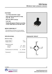
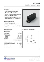
FEATURES<br />
· Pressure ranges from 25 to 500 Pa<br />
(0.1 to 2 inH 2<br />
O)<br />
· Pressure <strong>sensor</strong> based on thermal<br />
micro-flow measurement<br />
· Calibrated and temperature compensated<br />
· Analog output and digital SPI interface<br />
· High flow impedance<br />
→ very low flow-through leakage<br />
→ high immunity to dust and humidity<br />
→ no loss in sensitivity using long tubing<br />
· RoHS and REACH compliant<br />
· Quality Management System according to<br />
EN ISO 13485 and EN ISO 9001<br />
MEDIA COMPATIBILITY<br />
Air and other non-corrosive gases<br />
SPECIFICATIONS<br />
Maximum ratings<br />
Supply voltage V S<br />
<strong>LDE</strong>...3...<br />
2.70 ... 3.30 V DC<br />
<strong>LDE</strong>...6...<br />
4.75 ... 5.25 V DC<br />
Output current<br />
1 mA<br />
Lead specifications<br />
Average preheating temperature gradient 2.5 K/s<br />
Soak time<br />
ca. 3 min<br />
Time above 217°C<br />
50 s<br />
Time above 230°C<br />
40 s<br />
Time above 250°C<br />
15 s<br />
Peak temperature 260°C<br />
Cooling temperature gradient<br />
-3.5 K/s<br />
Temperature ranges<br />
Compensated 0 ... +70 °C<br />
Operating -20 ... +80 °C<br />
Storage -40 ... +80 °C<br />
Humidity limits (non-condensing)<br />
97 %RH<br />
Vibration 1<br />
20 g<br />
Mechanical shock 2<br />
500 g<br />
Specification notes:<br />
1. Sweep 20 to 2000 Hz, 8 min, 4 cycles per axis,<br />
MIL-STD-883, Method 2007.<br />
2. 5 shocks, 3 axes, MIL-STD-883E, Method 2002.4.<br />
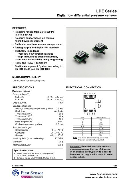
ELECTRICAL CONNECTION<br />
10 9 8 7 6<br />
1 2 3 4 5<br />
Pin<br />
Connection<br />
1,<br />
10<br />
NC<br />
2 Vs<br />
3 GND<br />
4,<br />
5<br />
Vout<br />
6 SCLK<br />
7 MOSI<br />
8 MIS O<br />
9 /CS<br />
Note: Pins 1 and 10 are internally connected.<br />
They can be externally grounded.<br />
Important: If the <strong>LDE</strong> <strong>sensor</strong> is used as a<br />
drop-in replacement for the LBA <strong>sensor</strong><br />
in an existing circuit, pins 6 to 9 have to<br />
be connected to ground in order to avoid<br />
<strong>sensor</strong> failure.<br />
E / 11815 / A8 1/10<br />
www.first-<strong>sensor</strong>.com<br />
www.<strong>sensor</strong>technics.com
<strong>LDE</strong> Series<br />
Digital low differential <strong>pressure</strong> <strong>sensor</strong>s<br />
PRESSURE SENSOR CHARACTERISTICS<br />
Part<br />
no.<br />
<strong>LDE</strong>S025U...<br />
<strong>LDE</strong>S050U...<br />
<strong>LDE</strong>S100U...<br />
<strong>LDE</strong>S250U...<br />
<strong>LDE</strong>S500U...<br />
<strong>LDE</strong>S025B...<br />
<strong>LDE</strong>S050B...<br />
<strong>LDE</strong>S100B...<br />
<strong>LDE</strong>S250B...<br />
<strong>LDE</strong>S500B...<br />
Operating<br />
<strong>pressure</strong><br />
0 ...25 Pa<br />
/ 0...0.25<br />
mbar<br />
( 0.1 inH<br />
O)<br />
2<br />
0 ...50 Pa<br />
/ 0...0.5<br />
mbar<br />
( 0.2 inH<br />
O)<br />
2<br />
0 ...100 Pa<br />
/ 0...1<br />
mbar<br />
( 0.4 inH<br />
O)<br />
2<br />
0 ...250 Pa<br />
/ 0...2.5<br />
mbar<br />
( 1 inH<br />
O)<br />
2<br />
0 ...500 Pa<br />
/ 0...5<br />
mbar<br />
( 2 inH<br />
O)<br />
2<br />
0 ...±25 Pa<br />
/ 0...±0.25<br />
mbar<br />
( ±0.1 inH<br />
O)<br />
2<br />
0 ...±50 Pa<br />
/ 0...±0.5<br />
mbar<br />
( ±0.2 inH<br />
O)<br />
2<br />
0 ...±100 Pa<br />
/ 0...±1<br />
mbar<br />
( ±0.4 inH<br />
O)<br />
2<br />
0 ...±250 Pa<br />
/ 0...±2.5<br />
mbar<br />
( ±1 inH<br />
O)<br />
2<br />
0 ...±500 Pa<br />
/ 0...±5<br />
mbar<br />
( ±2 inH<br />
O)<br />
2<br />
5<br />
Proof<br />
<strong>pressure</strong><br />
urst <strong>pressure</strong><br />
B<br />
5<br />
2 bar<br />
2 bar<br />
(30 psi)<br />
(30 psi)<br />
GAS CORRECTION FACTORS 11<br />
Gas<br />
type<br />
Dry air<br />
1. 0<br />
Oxygen (O 2 1.07<br />
Nitrogen (N 2 0.97<br />
Argon (Ar)<br />
0.98<br />
Carbon dioxide (CO 2 0.56<br />
Correction factor<br />
Specification notes (cont.):<br />
3. Total accuracy is the combined error from offset and span calibration, linearity, <strong>pressure</strong> hysteresis and temperature effects.<br />
4. The <strong>sensor</strong> is calibrated with a common mode <strong>pressure</strong> of 1 bar absolute. Due to the mass flow based measuring principle,<br />
variations in absolute common mode <strong>pressure</strong> need to be compensated according to the following formula:<br />
1bara<br />
∆P eff<br />
= True differential <strong>pressure</strong><br />
∆P eff = ∆P<strong>sensor</strong><br />
×<br />
P<br />
∆P<br />
abs<br />
<strong>sensor</strong><br />
= Differential <strong>pressure</strong> as indicated by output voltage<br />
P abs<br />
= Current absolute common mode <strong>pressure</strong><br />
5. The max. common mode <strong>pressure</strong> is 2 bar.<br />
6. Figure based on accelerated lifetime test corresponding to 1 year of life.<br />
7. The digital output signal is a signed, two's complement integer. Negative <strong>pressure</strong>s will result in a negative output.<br />
8. Please contact First Sensor for low power options.<br />
9. Non-linearity refers to a terminal based FSL (Fitting Straight Line) going through the actual zero <strong>pressure</strong> reading.<br />
10. Specification is preliminary. Data sheet is based on Pre-Series sample verification.<br />
11. For example with a <strong>LDE</strong>S500... <strong>sensor</strong> measuring CO 2<br />
gas, at full-scale output the actual <strong>pressure</strong> will be 500 Pa x 0.56 = 280 Pa.<br />
∆Peff = ∆P<strong>sensor</strong><br />
× gas correction factor ∆P eff<br />
= True differential <strong>pressure</strong><br />
= Differential <strong>pressure</strong> as indicated by output voltage<br />
∆P <strong>sensor</strong><br />
E / 11815 / A8 2/10<br />
www.first-<strong>sensor</strong>.com<br />
www.<strong>sensor</strong>technics.com
<strong>LDE</strong> Series<br />
Digital low differential <strong>pressure</strong> <strong>sensor</strong>s<br />
PERFORMANCE CHARACTERISTICS 4,10<br />
<strong>LDE</strong>...6...<br />
(V S<br />
=5.0 V DC<br />
, T A<br />
=20 °C, P Abs<br />
=1 bara, calibrated in air, output signals analog and digital are non-ratiometric to V S<br />
)<br />
all 25 Pa and 50 Pa devices<br />
C haracteristics<br />
M in.<br />
T yp.<br />
Max.<br />
Unit<br />
9<br />
Non-linearity<br />
±(1 % of reading +<br />
0.5 %FSS)<br />
3<br />
Total<br />
accuracy<br />
5 ...55 ° C<br />
±(1.5 % of reading +<br />
1.5 %FSS)<br />
0 ...70 °C<br />
±(3.5 % of reading +<br />
1.5 %FSS)<br />
Noise<br />
level<br />
0.03<br />
%FS<br />
Offset<br />
warm-up shift<br />
less than noise<br />
6<br />
Offset<br />
long term stability<br />
± 0.05<br />
± 0. 1<br />
Pa/year<br />
8<br />
Current<br />
consumption (no load)<br />
7 8 mA<br />
Response<br />
time (t63) 5<br />
Power-on time<br />
25<br />
ms<br />
Analog output (unidirectional devices)<br />
C haracteristics<br />
M in.<br />
T yp.<br />
Max.<br />
Zero<br />
<strong>pressure</strong> offset<br />
0.49<br />
0.50<br />
0.51<br />
Full<br />
scale span<br />
3.97<br />
4.00<br />
4.03<br />
Full<br />
scale output<br />
4.50<br />
Thermal<br />
effects Offset<br />
5...55<br />
° C<br />
±20<br />
0...70<br />
°C<br />
±40<br />
Span<br />
5...55<br />
° C<br />
± 1.25<br />
± 2<br />
0...70<br />
°C<br />
± 1.75<br />
±2.75<br />
Analog output (bidirectional devices)<br />
C haracteristics<br />
M in.<br />
T yp.<br />
Max.<br />
Zero<br />
<strong>pressure</strong> offset<br />
2.49<br />
2.50<br />
2.51<br />
Full<br />
scale span<br />
3.97<br />
4.00<br />
4.03<br />
Output<br />
at<br />
max. specified <strong>pressure</strong><br />
4.50<br />
at<br />
min. specified <strong>pressure</strong><br />
0.50<br />
Thermal<br />
effects Offset<br />
5...55<br />
° C<br />
±15<br />
0...70<br />
°C<br />
±30<br />
Span<br />
5...55<br />
° C<br />
± 1.25<br />
± 2<br />
0...70<br />
°C<br />
± 1.75<br />
±2.75<br />
Digital output<br />
C haracteristics<br />
M in.<br />
T yp.<br />
Max.<br />
7<br />
S cale factor ( digital output ) 0...25<br />
/ 0.. . ± 25 Pa<br />
1200<br />
0...50<br />
/ 0... ± 50 Pa<br />
600<br />
Zero<br />
<strong>pressure</strong> offset tolerance<br />
-0.<br />
2<br />
+0. 2<br />
Full<br />
scale span tolerance<br />
-0.75<br />
+0.75<br />
Thermal<br />
effects Offset<br />
5...55<br />
° C<br />
±60<br />
0...70<br />
°C<br />
±120<br />
Span<br />
5...55<br />
° C<br />
± 1 ±1.75<br />
0...70<br />
°C<br />
± 1.75<br />
±2.75<br />
Unit<br />
V<br />
mV<br />
%FSS<br />
Unit<br />
V<br />
mV<br />
%FSS<br />
Unit<br />
counts/Pa<br />
% FSS<br />
counts<br />
%FSS<br />
E / 11815 / A8 3/10<br />
www.first-<strong>sensor</strong>.com<br />
www.<strong>sensor</strong>technics.com
<strong>LDE</strong> Series<br />
Digital low differential <strong>pressure</strong> <strong>sensor</strong>s<br />
PERFORMANCE CHARACTERISTICS 4,10<br />
<strong>LDE</strong>...6...<br />
(V S<br />
=5.0 V DC<br />
, T A<br />
=20 °C, P Abs<br />
=1 bara, calibrated in air, output signals analog and digital are non-ratiometric to V S<br />
)<br />
all 100 Pa, 250 Pa and 500 Pa devices<br />
C haracteristics<br />
M in.<br />
T yp.<br />
Max.<br />
Unit<br />
9<br />
Non-linearity<br />
±(1 % of reading +<br />
0.5 %FSS)<br />
3<br />
Total<br />
accuracy<br />
5 ...55 ° C<br />
±(1.5 % of reading +<br />
1.5 %FSS)<br />
0 ...70 °C<br />
±(3.5 % of reading +<br />
1.5 %FSS)<br />
Noise<br />
level<br />
0.03<br />
%FS<br />
Offset<br />
warm-up shift<br />
less than noise<br />
6<br />
Offset<br />
long term stability<br />
± 0. 1 %FSS/year<br />
8<br />
Current<br />
consumption (no load)<br />
7 8 mA<br />
Response<br />
time (t63) 5<br />
Power-on time<br />
25<br />
ms<br />
Analog output (unidirectional devices)<br />
C haracteristics<br />
M in.<br />
T yp.<br />
Max.<br />
Zero<br />
<strong>pressure</strong> offset<br />
0.49<br />
0.50<br />
0.51<br />
Full<br />
scale span<br />
3.97<br />
4.00<br />
4.03<br />
Full<br />
scale output<br />
4.50<br />
Thermal<br />
effects Offset<br />
5...55<br />
° C<br />
±10<br />
0...70<br />
°C<br />
±12<br />
Span<br />
5...55<br />
° C<br />
± 1 ±1.75<br />
0...70<br />
°C<br />
± 2 ±2.75<br />
Analog output (bidirectional devices)<br />
C haracteristics<br />
M in.<br />
T yp.<br />
Max.<br />
Zero<br />
<strong>pressure</strong> offset<br />
2.49<br />
2.50<br />
2.51<br />
Full<br />
scale span<br />
3.97<br />
4.00<br />
4.03<br />
Output<br />
at<br />
max. specified <strong>pressure</strong><br />
4.50<br />
at<br />
min. specified <strong>pressure</strong><br />
0.50<br />
Thermal<br />
effects Offset<br />
5...55<br />
° C<br />
±10<br />
0...70<br />
°C<br />
±12<br />
Span<br />
5...55<br />
° C<br />
± 1 ±1.75<br />
0...70<br />
°C<br />
± 2 ±2.75<br />
Digital output<br />
C haracteristics<br />
M in.<br />
T yp.<br />
Max.<br />
7<br />
S cale factor ( digital output ) 0...100<br />
/ 0.. . ± 100 Pa<br />
300<br />
0...250<br />
/ 0... ± 250 Pa<br />
120<br />
0...500<br />
/ 0... ± 500 Pa<br />
60<br />
Zero<br />
<strong>pressure</strong> offset tolerance<br />
-0.<br />
1<br />
+0. 1<br />
Full<br />
scale span tolerance<br />
-0.75<br />
+0.75<br />
Thermal<br />
effects Offset<br />
5...55<br />
° C<br />
±30<br />
0...70<br />
°C<br />
±60<br />
Span<br />
5...55<br />
° C<br />
± 1 ±1.75<br />
0...70<br />
°C<br />
± 2 ±2.75<br />
E / 11815 / A8 4/10<br />
Unit<br />
V<br />
mV<br />
%FSS<br />
Unit<br />
V<br />
mV<br />
%FSS<br />
Unit<br />
counts/Pa<br />
% FSS<br />
counts<br />
%FSS<br />
www.first-<strong>sensor</strong>.com<br />
www.<strong>sensor</strong>technics.com
<strong>LDE</strong> Series<br />
Digital low differential <strong>pressure</strong> <strong>sensor</strong>s<br />
PERFORMANCE CHARACTERISTICS 4,10<br />
<strong>LDE</strong>...3...<br />
(V S<br />
=3.0 V DC<br />
, T A<br />
=20 °C, P Abs<br />
=1 bara, calibrated in air, output signals analog and digital are non-ratiometric to V S<br />
)<br />
all 25 Pa and 50 Pa devices<br />
C haracteristics<br />
M in.<br />
T yp.<br />
Max.<br />
Unit<br />
9<br />
Non-linearity<br />
±(1 % of reading +<br />
0.5 %FSS)<br />
3<br />
Total<br />
accuracy<br />
5 ...55 ° C<br />
±(1.5 % of reading +<br />
1.5 %FSS)<br />
0 ...70 °C<br />
±(3.5 % of reading +<br />
1.5 %FSS)<br />
Noise<br />
level<br />
0.03<br />
%FS<br />
Offset<br />
warm-up shift<br />
less than noise<br />
6<br />
Offset<br />
long term stability<br />
± 0.05<br />
± 0. 1<br />
Pa/year<br />
8<br />
Current<br />
consumption (no load)<br />
14<br />
16<br />
mA<br />
Response<br />
time (t63) 5<br />
Power-on time<br />
25<br />
ms<br />
Analog output (unidirectional devices)<br />
C haracteristics<br />
M in.<br />
T yp.<br />
Max.<br />
Zero<br />
<strong>pressure</strong> offset<br />
0.29<br />
0.30<br />
0.31<br />
Full<br />
scale span<br />
2.37<br />
2.40<br />
2.43<br />
Full<br />
scale output<br />
2.70<br />
Thermal<br />
effects Offset<br />
5...55<br />
° C<br />
±20<br />
0...70<br />
°C<br />
±40<br />
Span<br />
5...55<br />
° C<br />
± 1.25<br />
± 2<br />
0...70<br />
°C<br />
± 1.75<br />
±2.75<br />
Analog output (bidirectional devices)<br />
C haracteristics<br />
M in.<br />
T yp.<br />
Max.<br />
Zero<br />
<strong>pressure</strong> offset<br />
1.49<br />
1.50<br />
1.51<br />
Full<br />
scale span<br />
2.37<br />
2.40<br />
2.43<br />
Output<br />
at<br />
max. specified <strong>pressure</strong><br />
2.70<br />
at<br />
min. specified <strong>pressure</strong><br />
0.30<br />
Thermal<br />
effects Offset<br />
5...55<br />
° C<br />
±15<br />
0...70<br />
°C<br />
±30<br />
Span<br />
5...55<br />
° C<br />
± 1.25<br />
± 2<br />
0...70<br />
°C<br />
± 1.75<br />
±2.75<br />
Digital output<br />
C haracteristics<br />
M in.<br />
T yp.<br />
Max.<br />
7<br />
S cale factor ( digital output ) 0...25<br />
/ 0.. . ± 25 Pa<br />
1200<br />
0...50<br />
/ 0... ± 50 Pa<br />
600<br />
Zero<br />
<strong>pressure</strong> offset tolerance<br />
-0.<br />
2<br />
+0. 2<br />
Full<br />
scale span tolerance<br />
-0.75<br />
+0.75<br />
Thermal<br />
effects Offset<br />
5...55<br />
° C<br />
±60<br />
0...70<br />
°C<br />
±120<br />
Span<br />
5...55<br />
° C<br />
± 1 ±1.75<br />
0...70<br />
°C<br />
± 1.75<br />
±2.75<br />
Unit<br />
V<br />
mV<br />
%FSS<br />
Unit<br />
V<br />
mV<br />
%FSS<br />
Unit<br />
counts/Pa<br />
% FSS<br />
counts<br />
%FSS<br />
E / 11815 / A8 5/10<br />
www.first-<strong>sensor</strong>.com<br />
www.<strong>sensor</strong>technics.com
<strong>LDE</strong> Series<br />
Digital low differential <strong>pressure</strong> <strong>sensor</strong>s<br />
PERFORMANCE CHARACTERISTICS 4,10<br />
<strong>LDE</strong>...3...<br />
(V S<br />
=3.0 V DC<br />
, T A<br />
=20 °C, P Abs<br />
=1 bara, calibrated in air, output signals analog and digital are non-ratiometric to V S<br />
)<br />
all 100 Pa, 250 Pa and 500 Pa devices<br />
C haracteristics<br />
M in.<br />
T yp.<br />
Max.<br />
Unit<br />
9<br />
Non-linearity<br />
±(1 % of reading +<br />
0.5 %FSS)<br />
3<br />
Total<br />
accuracy<br />
5 ...55 ° C<br />
±(1.5 % of reading +<br />
1.5 %FSS)<br />
0 ...70 °C<br />
±(3.5 % of reading +<br />
1.5 %FSS)<br />
Noise<br />
level<br />
0.03<br />
%FS<br />
Offset<br />
warm-up shift<br />
less than noise<br />
6<br />
Offset<br />
long term stability<br />
± 0. 1 %FSS/year<br />
8<br />
Current<br />
consumption (no load)<br />
7 8 mA<br />
Response<br />
time (t63) 5<br />
Power-on time<br />
25<br />
ms<br />
Analog output (unidirectional devices)<br />
C haracteristics<br />
M in.<br />
T yp.<br />
Max.<br />
Zero<br />
<strong>pressure</strong> offset<br />
0.29<br />
0.30<br />
0.31<br />
Full<br />
scale span<br />
2.37<br />
2.40<br />
2.43<br />
Full<br />
scale output<br />
2.70<br />
Thermal<br />
effects Offset<br />
5...55<br />
° C<br />
±10<br />
0...70<br />
°C<br />
±12<br />
Span<br />
5...55<br />
° C<br />
± 1 ±1.75<br />
0...70<br />
°C<br />
± 2 ±2.75<br />
Analog output (bidirectional devices)<br />
C haracteristics<br />
M in.<br />
T yp.<br />
Max.<br />
Zero<br />
<strong>pressure</strong> offset<br />
1.49<br />
1.50<br />
1.51<br />
Full<br />
scale span<br />
2.37<br />
2.40<br />
2.43<br />
Output<br />
at<br />
max. specified <strong>pressure</strong><br />
2.70<br />
at<br />
min. specified <strong>pressure</strong><br />
0.30<br />
Thermal<br />
effects Offset<br />
5...55<br />
° C<br />
±10<br />
0...70<br />
°C<br />
±12<br />
Span<br />
5...55<br />
° C<br />
± 1 ±1.75<br />
0...70<br />
°C<br />
± 2 ±2.75<br />
Digital output<br />
C haracteristics<br />
M in.<br />
T yp.<br />
Max.<br />
7<br />
S cale factor ( digital output ) 0...100<br />
/ 0.. . ± 100 Pa<br />
300<br />
0...250<br />
/ 0... ± 250 Pa<br />
120<br />
0...500<br />
/ 0... ± 500 Pa<br />
60<br />
Zero<br />
<strong>pressure</strong> offset tolerance<br />
-0.<br />
1<br />
+0. 1<br />
Full<br />
scale span tolerance<br />
-0.75<br />
+0.75<br />
Thermal<br />
effects Offset<br />
5...55<br />
° C<br />
±30<br />
0...70<br />
°C<br />
±60<br />
Span<br />
5...55<br />
° C<br />
± 1 ±1.75<br />
0...70<br />
°C<br />
± 2 ±2.75<br />
E / 11815 / A8 6/10<br />
Unit<br />
V<br />
mV<br />
%FSS<br />
Unit<br />
V<br />
mV<br />
%FSS<br />
Unit<br />
counts/Pa<br />
% FSS<br />
counts<br />
%FSS<br />
www.first-<strong>sensor</strong>.com<br />
www.<strong>sensor</strong>technics.com
<strong>LDE</strong> Series<br />
Digital low differential <strong>pressure</strong> <strong>sensor</strong>s<br />
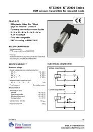
SPI - SERIAL PERIPHERAL INTERFACE<br />
Note: It is important to adhere to the communication protocol in order to avoid damage to the Sensor.<br />
Introduction<br />
The <strong>LDE</strong> serial interface is a high-speed asynchronous<br />
data input and output communication port. The serial<br />
interface operates in 3-wire SPI mode. In this setup,<br />
the MOSI and MISO pins are tied together, forming a<br />
bidirectional data line to the master microcontroller.<br />
The remaining serial interface connections consist of<br />
chip select (/CS) and serial clock (SCLK).<br />
Care should be taken to ensure that the <strong>sensor</strong> is<br />
properly connected to the master microcontroller.<br />
Refer to the manufacturer's datasheet for more<br />
information regarding physical connections.<br />
Signal control<br />
The serial interface is enabled by asserting /CS low.<br />
The serial input clock, SCLK, is gated internally to<br />
begin accepting the input data at MOSI, or sending<br />
the output data on MISO. When /CS rises, the data<br />
clocked into MOSI is loaded into an internal register.<br />
Note: If SPI communication is not required (i.e. only<br />
analog output is being used) pins 6 to 9 have to be<br />
connected to ground. Failure to do so may result in<br />
<strong>sensor</strong> failure.<br />
Data read<br />
When powered on, the <strong>sensor</strong> begins to continuously<br />
measure <strong>pressure</strong>. To initiate data transfer from the<br />
<strong>sensor</strong>, the following three unique bytes must be<br />
written sequentially, MSB first, to the MOSI pin (as<br />
shown in Fig. 1):<br />
Step<br />
Hexadecimal<br />
Binary<br />
1 0x2D<br />
B00101101<br />
2 x14<br />
3 x98<br />
Poll<br />
0 B00010100<br />
0 B10011000<br />
Description<br />
current <strong>pressure</strong> measurement<br />
Send result to data register<br />
Read data register<br />
The entire 16 bit content of the <strong>LDE</strong> register is then<br />
read out on the MISO pin, MSB first, by applying 16<br />
successive clock pulses to SCLK with /CS asserted low.<br />
From the digital <strong>sensor</strong> output the actual <strong>pressure</strong><br />
value can be calculated as follows:<br />
<strong>pressure</strong><br />
[ Pa]<br />
[ counts]<br />
digital output<br />
=<br />
⎡counts<br />
⎤<br />
scale factor⎢<br />
⎥<br />
⎣ Pa ⎦<br />
So for a ±250 Pa <strong>sensor</strong> (<strong>LDE</strong>S250B...) with a scale<br />
factor of 120 a digital output of 30 000 counts (7530’h)<br />
calculates to a positive <strong>pressure</strong> of 250 Pa. Similarly,<br />
a digital output of -30 000 counts (8AD0’h) calculates<br />
to a negative <strong>pressure</strong> of -250 Pa.<br />
/CS<br />
Step 1<br />
Step 2<br />
SCLK<br />
(CPOL=0)<br />
(CPAH=0)<br />
MOSI<br />
0 0 1 0 1 1 0 1 0 0 0 1 0 1 0 0<br />
MISO<br />
/CS<br />
Step 3<br />
Data from <strong>sensor</strong><br />
SCLK<br />
(CPOL=0)<br />
(CPAH=0)<br />
MOSI<br />
MISO<br />
1 0 0 1 1 0 0 0<br />
MSB<br />
15 14 13 12 11 10 9 8 7 6 5 4 3 2 1 0<br />
LSB<br />
Fig. 1: 3-wire mode data transfer<br />
E / 11815 / A8 7/10<br />
www.first-<strong>sensor</strong>.com<br />
www.<strong>sensor</strong>technics.com
<strong>LDE</strong> Series<br />
Digital low differential <strong>pressure</strong> <strong>sensor</strong>s<br />
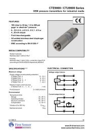
Serial interface specification<br />
Parameter<br />
Symbol<br />
Internal<br />
oscillator clock frequency<br />
f<br />
CLK<br />
External<br />
clock frequency<br />
f<br />
CLK<br />
External<br />
master clock input low time<br />
f<br />
CLKIN LO<br />
External<br />
master clock input high time<br />
f<br />
CLKIN HI<br />
Serial interface<br />
SCLK setup to falling edge /CS<br />
/ CS falling edge to SCLK rising edge setup time t<br />
SS<br />
/ CS idle time<br />
tCSI<br />
SCLK falling edge to data valid delay<br />
t O<br />
Data<br />
valid to SCLK rising edge setup time t S<br />
Data<br />
valid to SCLK rising edge hold time t H<br />
SCLK high pulse width<br />
t H<br />
SCLK low pulse width<br />
t L<br />
/ CS rising edge to SCLK rising edge hold time t<br />
SH<br />
/ CS falling edge to output enable<br />
t V<br />
/ CS rising edge to output disable<br />
t R<br />
C onditions<br />
M in.<br />
T yp.<br />
Max.<br />
SC(4:0)=00000<br />
I<br />
V = 0 in.<br />
E CKSEL<br />
O 3.<br />
3 4.15<br />
5. 3<br />
M 0. 2<br />
Max.<br />
5<br />
t = 1/ f<br />
E ECLK<br />
ECLK<br />
0<br />
t = 1/ f<br />
E ECLK<br />
ECLK<br />
0<br />
t SC<br />
30<br />
C<br />
30<br />
f = 4 MHz<br />
CLK<br />
. 5<br />
D<br />
C LOAD<br />
4 60<br />
4 60<br />
Unit<br />
MHz<br />
% t ECLK<br />
ns<br />
1 µ s<br />
= 15 pF<br />
80<br />
3<br />
3<br />
10<br />
ns<br />
10<br />
3<br />
= 15 pF<br />
25<br />
= 15 pF<br />
25<br />
D<br />
0<br />
D<br />
0<br />
C<br />
0<br />
C<br />
0<br />
C<br />
0<br />
D<br />
C LOAD<br />
T<br />
C LOAD<br />
/CS<br />
t CSI<br />
t SC<br />
t CSS<br />
t CL<br />
t CH<br />
t CSH<br />
SCLK<br />
t DS<br />
t DH<br />
MOSI<br />
t DV<br />
t t<br />
DO<br />
TR<br />
MISO<br />
Fig. 2: Timing diagram<br />
E / 11815 / A8 8/10<br />
www.first-<strong>sensor</strong>.com<br />
www.<strong>sensor</strong>technics.com
<strong>LDE</strong> Series<br />
Digital low differential <strong>pressure</strong> <strong>sensor</strong>s<br />
OUTLINE DRAWING<br />
<strong>LDE</strong>...E... (SMD, 2 ports same side)<br />
5.60<br />
±0.2<br />
0.25<br />
17.70<br />
12.70<br />
±0.15<br />
10 9 8 7 6<br />
High <strong>pressure</strong> port<br />
3.0<br />
13.85<br />
15.22<br />
18.03<br />
17.53<br />
±0.15<br />
10.70<br />
5.0<br />
Ø 2.20<br />
6.26<br />
1.43<br />
1 2 3 4 5<br />
5.08<br />
3.10<br />
±0.2<br />
2.54<br />
1.60<br />
±0.2<br />
0.51<br />
1.27<br />
5.60<br />
<strong>LDE</strong>...F... (DIP, 2 ports same side)<br />
5.60<br />
±0.2<br />
2.50<br />
17.70<br />
12.70<br />
±0.15<br />
10 9 8 7 6<br />
dimensions in mm<br />
High <strong>pressure</strong> port<br />
3.0<br />
0.25<br />
14.97<br />
18.03<br />
17.53<br />
±0.15<br />
10.70<br />
5.0<br />
Ø 2.20<br />
6.26<br />
7.85<br />
8.95<br />
±0.5<br />
15.65<br />
16.05<br />
1 2 3 4 5<br />
10.16<br />
2.54<br />
0.46<br />
3.10<br />
±0.2<br />
1.60<br />
±0.2<br />
5.60<br />
2.50<br />
dimensions in mm<br />
E / 11815 / A8 9/10<br />
www.first-<strong>sensor</strong>.com<br />
www.<strong>sensor</strong>technics.com
<strong>LDE</strong> Series<br />
Digital low differential <strong>pressure</strong> <strong>sensor</strong>s<br />
ORDERING INFORMATION<br />
Options<br />
Series<br />
<strong>LDE</strong><br />
S025<br />
Pressure<br />
range<br />
S050<br />
S100<br />
25 Pa<br />
( 0.1 inH O)<br />
2<br />
50 Pa<br />
( 0.2 inH O)<br />
2<br />
100 Pa<br />
( 0.4 inH O)<br />
2<br />
B<br />
U<br />
Calibratio<br />
n<br />
Housing<br />
Bidirectional<br />
Unidirectiona l<br />
E SMT, 2 ports<br />
same side<br />
F DIP, 2 ports<br />
same side<br />
Output<br />
3 non-ratiometric ,<br />
3 V supply<br />
6 non-ratiometric ,<br />
5 V supply<br />
S<br />
Grade<br />
High<br />
S250<br />
250 Pa<br />
( 1 inH O)<br />
2<br />
S500<br />
500 Pa<br />
( 2 inH O)<br />
2<br />
Example:<br />
<strong>LDE</strong><br />
S250<br />
B F 6 S<br />
First Sensor reserves the right to make changes to any products herein.<br />
First Sensor does not assume any liability arising out of the application<br />
or use of any product or circuit described herein, neither does it convey<br />
any license under its patent rights nor the rights of others.<br />
E / 11815 / A8 10/10<br />
www.first-<strong>sensor</strong>.com<br />
www.<strong>sensor</strong>technics.com