Spatially Resolved Surface Acoustic Wave Studies For Image ...
Spatially Resolved Surface Acoustic Wave Studies For Image ...
Spatially Resolved Surface Acoustic Wave Studies For Image ...

You also want an ePaper? Increase the reach of your titles
YUMPU automatically turns print PDFs into web optimized ePapers that Google loves.
<strong>Spatially</strong> <strong>Resolved</strong> <strong>Surface</strong> <strong>Acoustic</strong> <strong>Wave</strong> <strong>Studies</strong><br />
<strong>For</strong> <strong>Image</strong> Processing<br />
A.C. Müller 1 , H.-J. Kutschera 1 , and A. Wixforth 2<br />
1 Sektion Physik der Ludwig Maximilians Universität and CeNS, Geschwister-Scholl-Platz 1,<br />
80539 München, Germany<br />
2 Institut für Physik der Universität Augsburg, Experimentalphysik I, Universitätsstr. 1,<br />
86135 Augsburg, Germany<br />
Abstract— The interaction between a surface<br />
acoustic wave (SAW) and photogenerated charge<br />
carriers in a piezoelectric semiconductor substrate<br />
leads to pronounced changes in the transmission<br />
properties of the SAW. Depending on the<br />
charge carrier density one observes an attenuation<br />
and a change in sound velocity in a SAW delay<br />
line comprising a light sensitive semiconductor<br />
film. Using specially designed surface acoustic<br />
wave transducers, we are able to spatially resolve<br />
this interaction. The transducers used for this<br />
purpose consist of fan shaped interdigated metal<br />
fingers, which show a broadband frequency transmission.<br />
It turns out, that for such transducers<br />
the excited SAW propagates on a narrow path,<br />
whose position can be controlled by the driving<br />
frequency. We are able to reconstruct a 2D charge<br />
distribution by applying a tomographic technique<br />
or by nonlinear interaction between a probe and<br />
a perpendicular pump SAW crossing each other<br />
in the area where charge carriers are generated.<br />
I. Introduction<br />
Sophisticated surface acoustic wave (SAW) device<br />
technology together with well defined electronic<br />
properties of a semiconductor leads to very<br />
interesting applications of optical signal processing.<br />
In a piezoelectric crystal the SAW is accompanied<br />
by electric fields. The coupling is summarized in<br />
the electromechanical coupling coefficient K 2 eff .<br />
Mobile charge carriers move in the electric field<br />
and alter the velocity as well as the energy of the<br />
SAW due to finite resistance. <strong>For</strong> a conducting<br />
sheet close to the surface having a sheet conductivity<br />
σ the relative change in velocity ∆v/v and<br />
the attenuation Γ can be described by the following<br />
equations [1]<br />
∆v<br />
v<br />
= K2 eff<br />
2<br />
1<br />
1 + (σ/σ m ) 2 (1)<br />
E-mail: alexander.mueller@physik.uni-muenchen.de<br />
Γ = K2 eff<br />
2 k σ/σ m<br />
SAW<br />
1 + (σ/σ m ) 2 .<br />
(2)<br />
In these equations σ m denotes a critical sheet<br />
conductivity and k SAW the wave vector of the<br />
SAW. The largest energy transfer from the<br />
SAW to the charge carrier system occurs at<br />
σ = σ m . In a hybrid system consisting of a submicron<br />
thick semiconducting AlGaAs/InGaAsheterostructure<br />
on top of a strong piezoelectric<br />
substrate, like e.g. LiNbO 3 , attenuations of<br />
about 20 dB and phase shifts of several hundred<br />
degrees have been demonstrated [2]. Therefore,<br />
SAW measurements are a very sensitive tool to<br />
determine fundamental properties of semiconductors<br />
and have been used to investigate e.g. twodimensional<br />
electron systems in the quantum hall<br />
regime and the fractional quantum hall regime<br />
[3, 4]. With increasing potential amplitude Φ SAW<br />
the SAW modulates the homogeneous charge carrier<br />
system. In this regime the SAW velocity and<br />
damping respond in a nonlinear way since it differs<br />
from the linear regime described by equations<br />
(1) and (2) [5].<br />
In an illuminated semiconducting substrate,<br />
charge carriers are generated if the photon energy<br />
of the light is larger than the energy gap<br />
between valence and conductance band. If this<br />
is ensured, e.g. with a laser, the number of photogenerated<br />
charge carriers is proportional to the<br />
light intensity, which is in turn proportional to<br />
the conductivity σ. We investigated the interaction<br />
between SAWs and photogenerated charges<br />
in the linear as well as in the nonlinear regime in<br />
regard to its applicability to imaging devices.<br />
II. Fan-shaped Interdigital Transducer<br />
Spatial resolution is achieved by using so called<br />
fan shaped interdigital transducers, first introduced<br />
by Van de Heuvel [6]. In this special<br />
design of IDT the finger period is decreased<br />
monotonously along the aperture of the IDT
[7]. This causes an increase of the SAW frequency<br />
along the aperture. Hence, the resulting<br />
SAW intensity transmission signal of a delay<br />
line consisting of two fan-shaped IDTs is<br />
a frequency bandpass. <strong>For</strong> a frequency within<br />
such a bandpass the IDT matches the resonance<br />
only in a confined part of the aperture and<br />
launches a SAW only on a narrow path. If<br />
multiple split fingers are used, internal reflections<br />
are reduced and one has the opportunity<br />
to work also with higher harmonics of the resonant<br />
ground frequency with one single delay<br />
line. The value bandpass/middle frequency is<br />
approximately the tapering factor which represents<br />
a constant value. Therefore, the absolute<br />
value of the bandpass spreads with higher harmonics.<br />
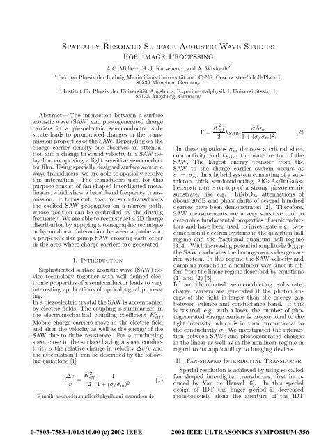
A typical transmission signal of this design<br />
is shown in fig. 1.<br />
The width of the SAW path limits the spatial<br />
resolution. It was already shown that the width<br />
decreases with increasing tapering factor before it<br />
reaches a minimum and then increases again due<br />
to diffraction [8]. Diffraction gains in importance,<br />
if the confinement reaches the order of the wavelength.<br />
Sauer et al. have been able to directly<br />
demonstrate diffraction for GaAs by X-ray imaging<br />
[9]. The typical width of a SAW path for an<br />
IDT with a tapering factor of 10%, an aperture<br />
of 450 m and a driving frequency of 600 MHz is<br />
approximately 50 m.<br />
In the case of a GaAs(001) surface the symmetries<br />
along the [110] and [-110] axis are equivalent.<br />
Therefore the transmission signals of perpendicular<br />
SAW delay lines are the same. The transmission<br />
signal in x and the perpendicular direction<br />
of a LiNbO 3 128 ◦ rot. Y-cut surface is different.<br />
On the last-mentioned substrate and for our delay<br />
line layout the transmission in x-direction is<br />
10 dB higher than in the perpendicular one.<br />
III. Sensitivity of Different Materials,<br />
the Linear Regime<br />
We measure amplitude and phase of the transmitted<br />
SAW signal with and without illumination<br />
of a spot being 5 m in diameter on our SAW<br />
delay line. The light source is an Argon laser<br />
(λ=488 nm). The SAW signal changes for frequencies<br />
and a corresponding SAW path intersecting<br />
the area where light induced charge carriers<br />
are present. We measure a peak in the relative<br />
change of phase and amplitude vs. the frequency<br />
bandpass. The FWHM of this peak corresponds<br />
to a larger spot size in real space than the spot of<br />
the light. The difference between the measured<br />
and the real spot size is due to the finite width<br />
transmission [dB]<br />
S 21<br />
-20<br />
-30<br />
-40<br />
-50<br />
-60<br />
-70<br />
-80<br />
1.harm. 3.harm. 5.harm. 7.harm.<br />
100 200 300 400 500 600 700 800 900<br />
frequency [MHz]<br />
Fig. 1. Transmission signal S 21 of a delay line with<br />
fan shaped split 4 IDTs. The taper factor is 10%.<br />
Maximum transmission occurs at the odd harmonics<br />
of the IDT periodicity. Here, we show the<br />
odd harmonics 1 through 7.<br />
of the SAW path (as shown in section II) and the<br />
diffusion of charge carriers.<br />
The relative change in phase and amplitude of<br />
the transmitted SAW signal changes with different<br />
material properties and different driving frequencies<br />
of the device. In this work we present<br />
three different GaAs devices. The first one is pure<br />
GaAs, which is characterized at the two different<br />
driving frequencies 440 and 825 MHz. With increasing<br />
frequency more wavelenghts fit into the<br />
illuminated area and hence the sensitivity of the<br />
device increases (compare triangled symbols in<br />
fig. 2). In GaAs grown at low temperatures (LT-<br />
GaAs) the mobility of electrons is lower (µ e in the<br />
order of 10 2 cm 2 /Vs) as compared to the electron<br />
mobility in GaAs grown at higher temperatures<br />
(µ e = 8·10 3 cm 2 /Vs). To reach the same sheet<br />
conductivity σ = en e µ e , where e is the elementary<br />
charge, one has to increase the two dimensional<br />
electron density n e . Consequently one has<br />
to generate more charge carriers to get the same<br />
conductivity. This is shown in fig. 2 squared data
el. phase shift [rad]<br />
1<br />
0.1<br />
0.01<br />
4<br />
2<br />
4<br />
2<br />
4<br />
2<br />
0.001<br />
ELO 600 MHz phase/amplitude<br />
GaAs 825 MHz phase/amplitude<br />
GaAs 440 MHz phase/amplitude<br />
LT-GaAs 440 MHz phase/amplitude<br />
10 -9 10 -7 10 -5 10 -3 10 -1<br />
laser power [W]<br />
10 -2<br />
10 -3<br />
10 -4<br />
10 -5<br />
10 -6<br />
10 -7<br />
Fig. 2. Dependence of maximum change in phase and<br />
amplitude of the SAW signal on different laser<br />
intensities and light sensitive GaAs films. The<br />
diameter of the laser spot at the surface is about<br />
5µm.<br />
IV. Novel SAW-Camera by Using<br />
Nonlinear Interaction<br />
To image a 2D charge carrier distribution with<br />
SAWs different approaches are possible. <strong>For</strong> measurements<br />
as described above the signal is a 1D<br />
projection of a 2D distribution. To reconstruct a<br />
2D image, one can apply tomographic techniques<br />
[7] as used in the x-ray absorption tomography<br />
of solid objects [11]. <strong>For</strong> this purpose one has<br />
to record a set of 1D projections for different angles<br />
between SAW path and the pattern of illumination.<br />
We break new ground in using two<br />
perpendicular SAWs interacting with each other<br />
via the electron-hole plasma. The transmission<br />
properties of a SAW with low intensity (probe<br />
SAW) changes with the intensity of the perpendicular<br />
SAW (pump SAW) in presence of charge<br />
carriers. We proofed the existence of this nonlinear<br />
regime (described in section I) for single<br />
delay lines as well as for two perpendicular ones.<br />
All devices are hybrid systems similar to what is<br />
described in section III. With fan-shaped IDTs<br />
we limit the SAW path in both directions and<br />
are therefore able to locally restrict the interaction<br />
to a small area of our device. This small<br />
area represents a pixel. The device consists of a<br />
350 nm thick ELO film (InGaAs-AlGaAs-GaAs<br />
heterostructure) a tapered IDT split 4 delay line<br />
in x-direction and a tapered IDT split 1 delay line<br />
in the perpendicular direction on the LiNbO 3 .<br />
<strong>For</strong> these experiments we used a pulsed laser<br />
diode at 670 nm to illuminate the ELO film. The<br />
diode was operated with a pulse repetition rate<br />
of 1 to 10 kHz and a pulse width of 10 to some<br />
hundred nanoseconds. The first experiments were<br />
rel. change in amplitude<br />
done using a network analyzer measuring the difference<br />
of the probe SAW signal with and without<br />
a continuous pump SAW (see fig. 3 (a) and (b)).<br />
<strong>For</strong> a better understanding we then altered our<br />
setup to do time resolved experiments. We are<br />
able to select the particular pulse time and pulse<br />
width of the light as well as of the two SAWs.<br />
We distinguish two different methods to image<br />
the charge carrier distribution.<br />
In the first case the pump SAW interacts with<br />
attendant charges before the probe SAW travels<br />
across the ELO film. The probe SAW signal is<br />
taken with and without pump SAW. The difference<br />
of both signals is non-zero when the pump<br />
SAW modifies the conductivity of the probe delay<br />
line (compare fig. 3 (c) and (d)). We believe that<br />
the pump SAW alters the conductivity by transporting<br />
some charges out of the sensitive area.<br />
In the second case both SAWs are launched at<br />
the same time and we used a lock-in technique by<br />
modulating the pump SAW with a square wave.<br />
We measured the modulation of the amplitude<br />
of the probe SAW fig. 3 (e) as well as the modulation<br />
of the cosine of the phase difference between<br />
probe SAW and corresponding reference<br />
frequency cos(∆φ) (shown in fig. 3 (f)). cos(∆φ)<br />
is different for each step of the frequency sweep.<br />
The reason is as follows. The number of acoustic<br />
wavelengths fitting in the delay line increases<br />
with the driving frequency. Hence, the phase of<br />
the transmitted SAW signal changes, while the<br />
phase of the corresponding reference frequency<br />
remains constant. The measuring technique is<br />
the most sensitive if cos(∆φ) = 0. If cos(∆φ) = 1<br />
the modulation is very small and hardly to measure.<br />
The last-mentioned is responsible for the<br />
dark horizontal stripes in fig. 3 (f).<br />
The performance of each IDT changes with the<br />
driving frequency and the ELO film is not perfectly<br />
homogeneous. Therefore the sensitivity<br />
changes with each pixel of our device. Despite<br />
this fact we are able to clearly interpret the<br />
2D structure of the photogenerated electron-hole<br />
plasma with a grey scale plot of the raw data.<br />
V. Conclusion<br />
<strong>Surface</strong> acoustic wave devices are a very sensitive<br />
tool to detect changes in the charge carrier<br />
system. We investigated the sensitivity of semiconducting<br />
SAW devices to illumination. The<br />
tested materials cover a range of over seven orders<br />
of magnitude in laser intensity from 2.5 · 10 −2 to<br />
5 · 10 5 W/cm 2 . It turns out that a semiconducting<br />
piezoelectric hybrid structure consisting of a<br />
submicron thick GaAs layer on top of a LiNbO 3
f probe<br />
[MHz]<br />
a) phase<br />
610<br />
600<br />
590<br />
580<br />
570<br />
560<br />
610<br />
600<br />
590<br />
580<br />
570<br />
560<br />
370 380 390 400<br />
c) amplitude<br />
610<br />
600<br />
590<br />
580<br />
570<br />
560<br />
370 380 390 400<br />
370 380 390 400 410 370 380 390 400 410<br />
e) amplitude<br />
610<br />
600<br />
590<br />
580<br />
570<br />
560<br />
pump SAW<br />
b) phase<br />
d) amplitude<br />
f) phase<br />
pump SAW<br />
370 380 390 400 410 370 380 390 400 410<br />
f pump<br />
[MHz]<br />
Fig. 3. (a) and (b) illustrates the signal of the probe<br />
SAW, measured with a network analyzer. The<br />
difference of the phase between pump SAW (continues<br />
wave) on and off is shown. (c) and (d)<br />
shows the difference of the amplitude of the probe<br />
SAW with pump SAW on and off. Both SAWs are<br />
pulsed. (e) and (f) illustrates the modulation of<br />
the probe SAW signal by modulating the intensity<br />
of the pump SAW with a lock-in technique.<br />
The insets of all figures sketch the pattern of the<br />
light on the semiconducting surface. <strong>For</strong> details<br />
see text.<br />
crystal is a very sensitive tool to detect small<br />
light intensities due to the large coupling coefficient<br />
Keff 2 . The adequate substrate to detect<br />
large light intensities is GaAs grown at low temperatures.<br />
This crystal has a lower charge carrier<br />
mobility because of a bigger defect concentration<br />
than GaAs grown at higher temperatures. <strong>For</strong><br />
high SAW intensities the conductivity depends<br />
on the SAW amplitude due to the strong piezoelectric<br />
fields and hence a band modulations in<br />
the semiconductor. The behavior for two perpendicular<br />
SAWs is similar. We demonstrated, that<br />
in the presence of photogenerated charge carriers<br />
the transmission properties of one SAW depends<br />
on the intensity of the perpendicular one.<br />
To receive spatial resolution we use fan-shaped<br />
IDTs. With this kind of IDT we make the SAW<br />
paths narrower and limit the area of interaction.<br />
This limited area represents a pixel of our SAWcamera<br />
and gives us the possibility to generate<br />
images of simple patterns of light induced charge<br />
carriers.<br />
Acknowledgment<br />
This work has been sponsored in part by Advalytix<br />
AG, Brunnthal, Germany, and in part by<br />
the Bayerische <strong>For</strong>schungsstiftung. Fruitful discussions<br />
with Prof. J.P. Kotthaus, and S. Manus<br />
(all University of Munich) are gratefully acknowledged.<br />
References<br />
[1] A. Wixforth, J.P. Kotthaus, and G. Weimann, Quantum<br />
Oscillations in <strong>Surface</strong>-<strong>Acoustic</strong>-<strong>Wave</strong> Attenuation<br />
Caused by a Two-Dimensional Electronic System,<br />
Phys. Rev. Lett. 56, 2104 (1986).<br />
[2] M. Rotter, A.V. Kalameitsev, A.O. Govorov,<br />
W. Ruile, and A. Wixforth, Charge Conveyance<br />
and Nonlinear Acoustoelectric Phenomena for Intense<br />
<strong>Surface</strong> <strong>Acoustic</strong> <strong>Wave</strong>s on a Semiconductor Quantum<br />
Well, Phys. Rev. Lett. 82, 2171 (1999).<br />
[3] A. Wixforth, J. Scriba, M. Wassermeier, J.P. Kotthaus,<br />
G. Weimann, and W. Schlapp, <strong>Surface</strong> acoustic<br />
waves on GaAs/Al xGa 1−xAs heterostructures,<br />
Phys. Rev. B. 40, 7874 (1989).<br />
[4] R.L. Willet, R.R. Ruel, W. West, and L.N. Pfeiffer,<br />
Experimental demonstration of a Fermi surface<br />
at one-half filling of the lowest Landau level<br />
Phys. Rev. Lett. 71, 3846 (1993).<br />
[5] A.V. Kalameitsev, A.O.Govorov, H.-J. Kutschera, A.<br />
Wixforth, Enhancement of the nonlinear acoustoelectric<br />
interaction in a photoexcited plasma in a quantum<br />
well, JETP Letter 72, 190 (2000).<br />
[6] A.P. Van de Heuvel, Use of rotated electrodes for amplitude<br />
weighting in interdigital surface wave transducers,<br />
Appl. Phys. Lett. 21, 280 (1972).<br />
[7] M. Streibl, F. Beil, A. Wixforth, C. Kadow, and<br />
A.C. Gossard, SAW Tomography - <strong>Spatially</strong> <strong>Resolved</strong><br />
Charge Detection by SAW in Semiconductor<br />
Structures for Imaging Applications, IEEE Ultrasonic<br />
Symposium 1999, p.11.<br />
[8] M. Streibl, H.-J. Kutschera, W. Sauer, and A. Wixforth<br />
Numerical and Experimental Analysis of Complex<br />
<strong>Surface</strong> <strong>Acoustic</strong> <strong>Wave</strong> Fields, IEEE Ultrasonic<br />
Symposium 2000.<br />
[9] W. Sauer, M. Streibl, T.H. Metzger,<br />
A.G.C. Haubrich, S. Manus, A. Wixforth J. Peisl,<br />
A. Mazuelas, J. Härtwig, and J. Baruchel, X-ray<br />
imaging and diffraction from surface phonons on<br />
GaAs, Appl. Phys. Lett. 75, 1709 (1999).<br />
[10] E. Yablonovich, D.M. Hwang, T.J. Gmitter, L.T. Florez,<br />
and J.P. Harbison, Van der Waals bonding<br />
of GaAs epitaxial liftoff films onto arbitrary substrates,<br />
Appl. Phys. Lett. 56, 2419 (1990); M. Rotter,<br />
C. Rocke, S. Böhm, A. Lorke, A. Wixforth, W. Ruile,<br />
and L. Korte, Single-chip fused hybrids for acoustoelectric<br />
and acousto-optic applications, Appl. Phys.<br />
Lett. 70, 2097 (1997).<br />
[11] J. C. Russ, The image Processing Handbook, second<br />
edition. Boca Raton, FL:CRC Press, p.674, 1995.