

UNITEST Echometer 3000
UNITEST Echometer 3000
UNITEST Echometer 3000

Create successful ePaper yourself
Turn your PDF publications into a flip-book with our unique Google optimized e-Paper software.
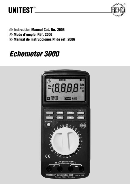
<strong>UNITEST</strong> ® ®<br />
Instruction Manual Cat. No. 2006<br />
Mode d´emploi Réf. 2006<br />
Manual de instrucciones N o de ref. 2006<br />
<strong>Echometer</strong> <strong>3000</strong>
Table of Contents<br />
Table of Contents..................................................................................Page<br />
1.0 Introduction / Scope of Supply........................................................17<br />
2.0 Transport and Storage ....................................................................18<br />
3.0 Safety Measures..............................................................................18<br />
4.0 General Information regarding <strong>UNITEST</strong> <strong>Echometer</strong> <strong>3000</strong> ..............19<br />
5.0 Control Elements / Display Elements ..............................................20<br />
6.0 Performance of Measurements ......................................................21<br />
6.1 Performance of Cable Length Measurements..................................21<br />
6.2 Performance of Cable Length Measurements within<br />
the Reference Range ......................................................................24<br />
6.2.1 Calibration of Customer Specific Cable Types..................................24<br />
6.2.2 Deletion of Reference Ranges ........................................................24<br />
6.3 Trouble Shooting ............................................................................25<br />
6.4 Performance of Resistance Measurements /<br />
Continuity Tests ..............................................................................25<br />
7.0 Internal Data Memory / Cumulative Data Memory ..........................26<br />
7.1 Saving Measurement Results..........................................................26<br />
7.1.1 Deletion of all Saved Measurement Results ....................................26<br />
7.1.2 Deletion of the Last Measurement Result ........................................26<br />
7.2 Cumulate and Save Measurement Results ......................................26<br />
8.0 Transfer of Saved Measurement Values to a PC ..............................27<br />
9.0 Maintenance....................................................................................27<br />
9.1 Cleaning ..........................................................................................27<br />
9.2 Battery Replacement ......................................................................27<br />
10.0 Calibration Interval ..........................................................................27<br />
11.0 Technical Data ................................................................................28<br />
16
Introduction / Scope of Supply<br />
References marked on instrument or in<br />
instruction manual:<br />
Warning of a potential danger, comply with instruction<br />
manual.<br />
Reference. Please use utmost attention.<br />
Caution! Dangerous voltage. Danger of electrical<br />
shock.<br />
Continuous double or reinforced insulation<br />
complies with category II.<br />
Conformity symbol, the instrument complies<br />
with the valid directives. It complies with the<br />
EMC Directive (89/336/EEC), Standards EN<br />
50081-1and EN 50082-1 are fulfilled. It also<br />
complies with the Low Voltage Directive<br />
(73/23/EEC), Standard EN 61010-1 is fulfilled.<br />
The instruction manual contains information<br />
and references, necessary for safe operation<br />
and maintenance of the instrument.<br />
Prior to using the instrument (commissioning<br />
/ assembly) the user is kindly requested to<br />
thoroughly read the instruction manual and<br />
comply with it in all sections.<br />
Failure to read the instruction manual or to<br />
comply with the warnings and references<br />
contained herein can result in serious bodily<br />
injury or instrument damage.<br />
1.0 Introduction / Scope of Supply<br />
You have acquired a high standard measurement instrument<br />
supplied by the company Ch. BEHA GmbH<br />
which is able to perform reproducible measurements<br />
over a very long time period. The company<br />
Ch. BEHA GmbH is a member of the world-wide operating<br />
BEHA group. The head office of the BEHA<br />
group is located in Glottertal/Schwarzwald, together<br />
with the technological centre. The BEHA group is<br />
a leading enterprise for test and measurement instruments.<br />
The <strong>UNITEST</strong> <strong>Echometer</strong>s are universally usable<br />
cable length measurement instruments. They have<br />
been built in compliance with the most recent prescriptions<br />
and gurantee safe and reliable measurements.<br />
The <strong>UNITEST</strong> <strong>Echometer</strong>s are a valuable<br />
support for trade and industry for tally measurements,<br />
inventories, and residual length measurements.<br />
The instruments have the following characteristics:<br />
• <strong>Echometer</strong> for easy and time efficient measurement<br />
of cable lengths in trade, industry, utility<br />
companies, and specialist electronic stores.<br />
• Only one cable end is required. Thus, conductors<br />
already installed or cable drums can be measured,<br />
thus saving time.<br />
• 58 fixed, pre-programmed measurement ranges<br />
representing the most common cable cross sections<br />
• 87 variable measurement ranges, individually<br />
programmable by the user to measure customer<br />
specific conductor and cable types<br />
• Detecting single or multi-wire conductor interruptions<br />
or short-circuits for trouble shooting<br />
• Cable and conductor length measurement up to<br />
approx. 2000 m (depending on the type of conductor)<br />
• Internal data memory to save 500 measurements<br />
for inventories, tally measurements, cable return<br />
measurements, etc.<br />
• RS232 interface for transfer and further PC processing<br />
of measurement data<br />
• Cumulative memory to measure and cumulate<br />
several cable rings of the same type of conductor,<br />
saving time and money<br />
• Additional resistance measurement up to 2000<br />
Ohm and acoustic continuity test<br />
• Display light for better visibility while working in<br />
badly illuminated environments, such as storage<br />
areas<br />
• Automatic power off<br />
English<br />
17
Transport and Storage / Safety Measures<br />
The scope of supply comprises of:<br />
1 <strong>UNITEST</strong> <strong>Echometer</strong> <strong>3000</strong><br />
2 Test leads red/black<br />
2 Alligator clamps<br />
1 Carrying holster<br />
1 Battery 9 V, IEC 6LR61<br />
3 Concise reference guides<br />
1 Instruction manual<br />
Accessories:<br />
Windows Software <strong>UNITEST</strong> ”Report Studio”<br />
Order No: 1207<br />
2.0 Transport and Storage<br />
Please keep the original packaging for later transport,<br />
e.g. for calibration. Any transport damage due<br />
to faulty packaging will be excluded from warranty<br />
claims.<br />
In order to avoid instrument damage, it is advised<br />
to remove accumulators when not using<br />
the instrument over a certain time period. However,<br />
should the instrument be contaminated<br />
by leaking battery cells, you are kindly requested<br />
to return it to the factory for cleaning<br />
and inspection.<br />
Instruments must be stored in dry and closed<br />
areas. In the case of an instrument being transported<br />
in extreme temperatures, a recovery<br />
time of minimum 2 hours is required prior to<br />
instrument operation.<br />
3.0 Safety Measures<br />
The <strong>UNITEST</strong> Cable Length Meters have been built<br />
and tested in compliance with the valid Regulations<br />
and have left the company in safe and perfect condition.<br />
To maintain this condition, the user must<br />
comply with the safety references contained in this<br />
instruction manual.<br />
Prior to any operation, ensure that connecting<br />
leads and instrument are in perfect condition.<br />
The respective accident prevention regulations<br />
established by the professional association for<br />
electrical systems and equipment must be<br />
strictly met at all times.<br />
The instrument may only be used within the operating<br />
ranges as specified in the technical data<br />
section.<br />
Prior to opening, the instrument has to be<br />
switched off and disconnected from any circuit.<br />
Avoid any heating up of the instrument by direct<br />
sunlight to ensure perfect functioning and<br />
long instrument life.<br />
Appropriate Usage<br />
The instrument may only be used under those<br />
conditions and for those purposes for which it<br />
was built. For this reason, in particular the safety<br />
references,as well as the technical data including<br />
environmental conditions and the<br />
usage in dry environments must be followed at<br />
all times.<br />
The operational safety of the instrument is noi<br />
longer guaranteedafter unauthorised modifications<br />
or changes.<br />
The instrument may only be opened by an authorised<br />
service technician, e.g. for fuse replacement.<br />
Never apply voltage to any of the instrument<br />
measurement ranges. Always verify that the<br />
circuits are not live using a dual-pole voltage<br />
tester (e.g. <strong>UNITEST</strong> 2000 alpha)!<br />
18
General Information<br />
4.0 General Information regarding<br />
<strong>UNITEST</strong> <strong>Echometer</strong>s <strong>3000</strong><br />
The <strong>UNITEST</strong> <strong>Echometer</strong>s are measurement instruments<br />
for swift, easy and precise determination of<br />
the length of a cable or a conductor as well as for<br />
resistance measurements.<br />
The cable length determination is carried out in<br />
accordance with the pulse reflection procedure.<br />
The <strong>UNITEST</strong> <strong>Echometer</strong> <strong>3000</strong> enables the measurement<br />
of the most conventional cable and conductor<br />
cross sections. Additionally, 87 freely adjustable<br />
cable and conductor cross sections are<br />
available for programming and measurement.<br />
Simply connect the instrument alligator clamps to<br />
the ends of a cable or a conductor and set the respective<br />
measurement range. The conductor length<br />
is clearly indicated on the digital instrument display.<br />
Hereby, pulses are send into a cable which "travel”<br />
at a certain velocity along the cable. If these pulses<br />
hit the cable end they are reflected and return to the<br />
starting point.<br />
The built-in memory is used to save measurement<br />
results and to transfer the data via interface to a PC.<br />
English<br />
The <strong>UNITEST</strong> <strong>Echometer</strong> <strong>3000</strong> calculates the cable<br />
length on the basis of time difference between emission<br />
and reception of the pulses.<br />
If a short-circuit or an interruption is present in the<br />
conductor to be measured the digital display indicates<br />
the length of the conductor up to the fault location.<br />
This allows an easy and fast fault localization.<br />
The travel time required only depends on the dispersion<br />
velocity of the travelling pulse. In turn, the<br />
dispersion velocity is determined by the make and<br />
structure of a cable. This means, that every cable<br />
has a certain characteristic dispersion velocity and,<br />
thus, different travel times.<br />
The cable characteristics saved in the <strong>Echometer</strong><br />
(TAB range) represent a cable mean value established<br />
by the various manufacturers and ensure approximate<br />
measurements. To carry out precise<br />
measurements, the user may calibrate the cable<br />
supplied by a certain manufacturer and permanently<br />
store the cable characteristics in the instrument<br />
memory for subsequent measurements (REF<br />
range).<br />
19
Control Elements / Display Elements / Description of the Menu Keys<br />
5.0 Control Elements / Display Elements<br />
Control Elements:<br />
1. RS232 interface<br />
2. LCD<br />
3. Function keys<br />
4. Push-button on/off/start<br />
5. Selection dial for the measurement ranges<br />
6. Measurement input sockets<br />
7. Display light<br />
1<br />
Description of the Menu Keys:<br />
Shift<br />
Shift<br />
The second function of the double function keys is<br />
only activated when pressing the keys together with<br />
the "Shift” key.<br />
TAB/REF<br />
The ''TAB/REF'' key is used to change into different<br />
levels: Table I, Table II, Reference range I, Reference<br />
range II, and Reference range III.<br />
7<br />
Display Elements:<br />
1. Emergency reflective triangle<br />
2. Error display<br />
3. Battery replacement required<br />
4. Measurement value<br />
5. Measurement unit<br />
6. Memory display (M)<br />
7. Table / reference range display<br />
8. Cumulative value memory display (Res)<br />
9. Short-circuit display (COMP)<br />
6<br />
1 2 3<br />
7<br />
9<br />
4 5<br />
8<br />
2<br />
3<br />
4<br />
5<br />
6<br />
m/ft<br />
m/ft<br />
Switching between the measurement units<br />
meter/feet.<br />
Clear all<br />
Send<br />
Send<br />
The ''Send'' key is used to start the transfer of the<br />
data memorised in the <strong>UNITEST</strong> <strong>Echometer</strong> <strong>3000</strong> to<br />
the PC.<br />
Clear all<br />
Shift +<br />
Send Clear all<br />
''Clear all'' deletes the total internal memory. The<br />
cumulative data memory is not cleared.<br />
The ''Clear all'' key is activated when the ''Shift'' key<br />
is pressed at the same time.<br />
Res+<br />
The ''Res+'' key is used to activate the cumulative<br />
data memory. The measurement data within the<br />
same measurement range is added, i.e. several<br />
rings of the same cable type can be added.<br />
Shift + [Light]<br />
The ''Light key is used to switch on the display light.<br />
To reduce the battery consumption, the display light<br />
is switched off after approx. 30s. after the last key<br />
option.<br />
The ''Light” is only activated when the "Shift” key is<br />
pressed at the same time.<br />
[Arrow down]<br />
When the key and the key are<br />
pressed at the same time, the reference cable<br />
lengths within the reference range can be set.<br />
20
29<br />
Performance of Measurements / Performance of Cable Lengths Measurements<br />
Shift<br />
+ Store REF<br />
The ''Store REF'' key is used to save the previously<br />
set reference cable length.<br />
The ''Store REF'' is only activated when the "Shift”<br />
key is pressed at the same time.<br />
[Arrow up]<br />
The [arrow up] key together with the [arrow down]<br />
key are used to set the reference cable lengths within<br />
the reference range.<br />
Store<br />
The ''Store'' key is used to save a measurement result.<br />
If several measurement values have been cumulated<br />
within the cumulative data memory, the<br />
sum can be imported into the data memory by<br />
pressing the ''Store'' key.<br />
Shift<br />
+ Clear one<br />
''Clear one'' is pressed to clear the last measurement<br />
value saved. The cumulative data memory is<br />
not affected. The ''Clear one '' key is only activated<br />
when the "Shift” key is pressed at the same time.<br />
• Additional measurement errors up to 10 % reading<br />
may occur due to the differing cable structure<br />
and material, depending on the manufacturer.<br />
" Switch on the <strong>UNITEST</strong> <strong>Echometer</strong> pressing the<br />
Start/Off<br />
key.<br />
" Connect the red test lead to the red socket and<br />
the black test lead to the black socket of the m<br />
range.<br />
" Connect two parallel leads of the cable to be<br />
measured using the alligator clamps.<br />
" To set the desired measurement unit (m/ft),<br />
press the<br />
Shift<br />
und m/ft key. ''m'' or<br />
''ft'' is displayed.<br />
" Set the measurement range selection dial in accordance<br />
with the conductor types in Table I or<br />
II. The key is used to switch to the measurement<br />
ranges of table II. "TAB II” appears on<br />
the display.<br />
If the message ''- - -'' is displayed, the <strong>UNITEST</strong><br />
<strong>Echometer</strong> is ready to perform measurements.<br />
Start/Off<br />
" Start measurement using the key.<br />
English<br />
A single signal sound is audible and the measurement<br />
value of the conductor length in the<br />
pre-selected unit (m/ft) is displayed.<br />
m<br />
6.0 Performance of Measurements<br />
6.1 Performance of Cable Lengths<br />
Measurements<br />
• The leads to be measured must be positioned next<br />
to each other. It is not possible to measure individual<br />
wires.<br />
• For coaxial cable measurements, connect the internal<br />
conductors to the read sockets and the<br />
sheath to the black socket.<br />
• Only connect one lead per measurement connection.<br />
Ω<br />
m<br />
<strong>Echometer</strong> 6<br />
It is preferable to carry out the measurement<br />
with open cable ends. If the cable end has a<br />
short-circuit the message COMP is displayed.<br />
Short-circuited cable ends cause an increasing<br />
measurement error of the <strong>UNITEST</strong> <strong>Echometer</strong><br />
<strong>3000</strong>.<br />
21
Switch position assignment<br />
Table I:<br />
Switch Position Table I (TAB I) Maximum Length<br />
1 NYM-J 3x1,5 mm 2 1200 m<br />
2 NYM-J 4x1,5 mm 2 1200 m<br />
3 NYM-J 5x1,5 mm 2 1200 m<br />
4 NYM-J 7x1,5 mm 2 1200 m<br />
5 NYM-J 3x2,5 mm 2 1200 m<br />
6 NYM-J 4x2,5 mm 2 1200 m<br />
7 NYM-J 5x2,5 mm 2 1200 m<br />
8 NYM-J 7x2,5 mm 2 1200 m<br />
9 NYM-J 5x4 mm 2 1200 m<br />
10 NYM-J 5x6 mm 2 1200 m<br />
11 NYM-J 4x10 mm 2 1200 m<br />
12 NYM-J 5x10 mm 2 1200 m<br />
13 NYM-J 4x16 mm 2 1200 m<br />
14 NYM-J 5x16 mm 2 1200 m<br />
15 NYY-J 3x1,5 mm 2 1200 m<br />
16 NYY-J 4x1,5 mm 2 1200 m<br />
17 NYY-J 5x1,5 mm 2 1200 m<br />
18 NYY-J 3x2,5 mm 2 1200 m<br />
19 NYY-J 5x2,5 mm 2 1200 m<br />
20 NYY-J 4x10 mm 2 1200 m<br />
21 NYY-J 5x10 mm 2 1200 m<br />
22 NYY-J 4x16 mm 2 1200 m<br />
23 NYY-J 4x25 mm 2 1200 m<br />
24 NYY-J 4x35 mm 2 1200 m<br />
25 JYSTY 2x2x0,6 mm 500 m<br />
26 JYSTY 4x2x0,6 mm 500 m<br />
27 JYSTY 6x2x0,6 mm 500 m<br />
28 JYSTY 2x2x0,8 mm 500 m<br />
29 JYSTY 4x2x0,8 mm 500 m<br />
22
Table II:<br />
Switch Position Table II (TAB II) Maximum Length<br />
1 JYSTY 6x2x0,8 mm 500 m<br />
2 SAT:LCD 58 1500 m<br />
3 SAT:LCD 61 1500 m<br />
4 SAT: LCD 79 1900 m<br />
5 SAT:LCD 90 1900 m<br />
6 SAT:LCD 95 2000 m<br />
7 SAT:LCD 99 2000 m<br />
8 SAT:LCM 13 1500 m<br />
9 SAT:LCM 14 1900 m<br />
10 SAT:0,8/3,5 ALG; 1,1/5,0 ALG; 1900 m<br />
1,65/7,2 ALG; 2,2/9,6 ALG; SAT-MINI 1 (*)<br />
11 SAT:SAT <strong>3000</strong> (*) 1900 m<br />
12 SAT:2-SAT <strong>3000</strong> midi; 2-SAT <strong>3000</strong> mini, 1900 m<br />
2-SAT <strong>3000</strong> mini round 4-SAT <strong>3000</strong> (*)<br />
13 Cable TV: 0,6L/3,0 ALG; 0,63/3,0 ALG; 0,4/2,45 ALG; 1500 m<br />
0,8/3,7 ALG; 0,7/4,4 ALG; 0,7/4,5 ALG-H;<br />
0,7/4,8 C ALG; 0,7/4,8 CW ALG; 1,1/7,3 ALG;<br />
1,1/7,3 ALG-T; 1,8/11,5 FG; A-2YK2YliKx 1,1/7,3 (*)<br />
14 Cable TV: 0,4/1,75 ALG (*) 1800 m<br />
15 Cable TV: 0,4/2,0 ALG (*) 1900 m<br />
16 Cable TV: A-2YOK2YlnKx 2; 2/8,8 A-2YOK2YlqKx 3,3/13,5(*) 2000 m<br />
17 TV:0632-75vz (*) 1500 m<br />
18 TV: 0938-60vz 1600 m<br />
0637-75bl; 0637-75vz; 0637-75vs; 0632-75bl (*)<br />
19 TV: 1046-75bl (*) 1900 m<br />
20 RG6/U; RG8/U; RG11/U; RG58/U; RG058/U; 1500 m<br />
RG59/U; RG174/U; RG213/U; RG214/U; RG215/U;<br />
RG216/U; RG217/U; RG218/U; RG223/U; RG316/U<br />
21 RG178/U; RG179/U; RG180/U; RG187/U 1600 m<br />
22 RG62/U; RG71/U 1600 m<br />
23 DATA:10BaseT (RG58/U) 1500 m<br />
24 DATA:YELLOW-CABLE 1900 m<br />
25 DATA:LAN300 500 m<br />
J-02YS(C)Y 4x2xAWG22<br />
26 Phone:JYSTY 2x2x0,6 mm 500 m<br />
27 HIFI:NYFAZ 2x0,5 mm (**) 500 m<br />
28 HIFI:NYFAZ 2x0,75 mm (**) 500 m<br />
29 HIFI:NYFAZ 2x1,5 mm (**) 500 m<br />
English<br />
* Helu Cable ** loudspeaker cable<br />
-The values and reference ranges refer to measurements with open cable ends. Measurements with short-circuited<br />
ends lend to results with increased measurement errors.<br />
23
29<br />
Performance of Measurements<br />
6.2 Performance of Cable Length<br />
Measurements within the Reference Range<br />
To allow measurement of customer specific cable<br />
types, reference ranges have been integrated in the<br />
<strong>UNITEST</strong> <strong>Echometer</strong> <strong>3000</strong>. The user can calibrate<br />
and save the reference ranges for the specific cable<br />
types.<br />
6.2.1 Calibration of Customer Specific Cable<br />
Types<br />
" Switch on <strong>UNITEST</strong> <strong>Echometer</strong> using the<br />
Start/Off<br />
key.<br />
" Change to the reference range pressing<br />
the key, e.g. reference level I. REF I is<br />
indicated on the display.<br />
" Connect the red test lead to the red socket and<br />
the black test lead to the black socket of the m-<br />
range.<br />
" Connect two leads in parallel of the cable to be<br />
measured using the alligator clamps.<br />
" To set the measurement unit (m/ft) press the<br />
m/ft key. ''m'' or ''ft'' is indicated on the display.<br />
" Set measurement range selection dial to a free<br />
memory location, e.g. switch position 1.<br />
100.0 m is indicated on the display.<br />
" Set the known length of the cable to be calibrated<br />
using the or keys.<br />
" Save the length of the reference cable pressing<br />
Shift<br />
and keys. A simple signal<br />
sound is audible.<br />
The reference range accuracy values depend<br />
on the calibration accuracy of the customer<br />
specific cable type. To comply with the accuracy<br />
values in accordance with the specified<br />
technical data, the user must perform the calibration<br />
of the cable type as described in the instruction<br />
manual.<br />
6.2.2 Deletion of Reference Ranges<br />
If the user requires to assign the reference ranges<br />
to other cable types, the reference range must first<br />
be deleted.<br />
Free memory locations of the reference ranges are<br />
indicated by the display ''100.0''. Already assigned<br />
memory locations are indicated by the display ''- -<br />
-''.<br />
" Set <strong>UNITEST</strong> <strong>Echometer</strong> <strong>3000</strong> to the reference<br />
range to be deleted.<br />
''- - -'' is indicated on the display.<br />
" Press the key once. The message<br />
''100.0'' is displayed.<br />
" If the alligator clamps are open press<br />
Shift<br />
and keys. An error measurement<br />
is generated and indicated by the message<br />
''Error''.<br />
The reference range is deleted.<br />
m<br />
Note cable type, switch position and reference level<br />
Now the length measurement of the cable type calibrated<br />
can be performed as described in section<br />
6.1.<br />
Ω<br />
m<br />
<strong>Echometer</strong> 6<br />
24
29<br />
Start/off<br />
29<br />
Performance of Measurements<br />
6.3 Trouble-Shooting<br />
The <strong>UNITEST</strong> <strong>Echometer</strong> <strong>3000</strong> enables to locate<br />
faults in cables or conductors.<br />
The user must check that the circuits are not<br />
live !<br />
6.4 Performance of Resistance Measurements<br />
The <strong>UNITEST</strong> <strong>Echometer</strong> <strong>3000</strong> can easily and precisely<br />
determine electrical resistances.<br />
The user must check that the circuits are not<br />
live !<br />
" Switch on the <strong>UNITEST</strong> <strong>Echometer</strong> <strong>3000</strong> pressing<br />
the key.<br />
Start/Off<br />
" Change to the reference range pressing the<br />
key, e.g. Reference level I. REF I is indicated<br />
on the display.<br />
" Connect the red test lead to the red socket and<br />
the black test lead to the black socket of the m<br />
range.<br />
" Connect the faulty leads of the conductor to be<br />
measured using the alligator clamps.<br />
" Set the measurement unit (m/ft) pressing the<br />
m/ft key. ''m'' or ''ft'' is displayed.<br />
" Set the measurement range selection dial in accordance<br />
with the conductor types in Tables I or<br />
II. The key is used to change to the<br />
measurement ranges of Table II. ''TAB II'' is indicated<br />
on the display.<br />
" Switch on the <strong>UNITEST</strong> <strong>Echometer</strong> <strong>3000</strong> pressing<br />
the key.<br />
Start/Off<br />
" Set the measurement range selection to the position<br />
"Ohm”.<br />
" The message ''>1999,9 Ohm'' is displayed.<br />
" Connect the red test lead to the red socket and<br />
the black test lead to the black socket of the Ohm<br />
range.<br />
" Connect both ends of the resistance to be measured<br />
using the alligator clamps.<br />
The resistance measured is indicated on the display.<br />
If the resistance is below approx. 10 Ohm an<br />
acoustic signal is audible.<br />
English<br />
If the message ''- - -'' is displayed, the <strong>UNITEST</strong><br />
<strong>Echometer</strong> is ready to perform measurements.<br />
Ω<br />
Start/Off<br />
" Start the measurement pressing the key.<br />
R < 10Ω<br />
A single signal sound is audible and the measurement<br />
value of the conductor length in the<br />
pre-selected unit (m/ft) up to the error location<br />
is displayed. If the message "COMP is displayed,<br />
the leads have a short-circuit.<br />
Ω<br />
m<br />
<strong>Echometer</strong> 6<br />
Short-circuited cable ends cause an increasing<br />
measurement error of the <strong>UNITEST</strong> <strong>Echometer</strong><br />
<strong>3000</strong>.<br />
m<br />
Unterbrechung<br />
20m<br />
Ω<br />
m<br />
<strong>Echometer</strong> 6<br />
Kurzschluss<br />
m<br />
20m<br />
COMP<br />
25
Performance of Measurements<br />
7.0 Internal Measurement Data Memory /<br />
Cumulative Data memory<br />
7.1 Saving Measurement Results<br />
" Perform the measurement as described in 6.2.<br />
" The measurement result is indicated on the display.<br />
" Press the key. The result measured is<br />
stored in the internal <strong>UNITEST</strong> <strong>Echometer</strong> <strong>3000</strong><br />
memory. A single acoustic signal is audible and<br />
the memory location, e.g. 1 is briefly displayed.<br />
Furthermore, the symbol ''M'' is displayed and<br />
indicates that the measurement data has been<br />
saved in the internal memory.<br />
When the key is pressed again a double<br />
acoustic signal is audible and indicates that<br />
further saving of this measurement is not possible.<br />
After a new measurement, new results<br />
can be stored again.<br />
7.1.1 Deletion of all Saved Measurement<br />
Results<br />
Clear all<br />
Press the<br />
Shift<br />
and<br />
Send<br />
keys.<br />
A brief acoustic signal is audible and ''0'' is briefly<br />
displayed to indicate that the memory has been<br />
cleared. The symbol "M” disappears from the display.<br />
The cumulative data memory is not affected by the<br />
clearing procedure.<br />
7.2 Adding and Saving Measurement Results<br />
The <strong>UNITEST</strong> <strong>Echometer</strong> is equipped with a cumulative<br />
data memory enabling the measurement of<br />
several cable rings of the same type , and to perform<br />
cumulation of the values.<br />
" Perform the measurements as described in section<br />
6.2.<br />
" The measurement result is displayed.<br />
" Press the key. The measurement result<br />
is added to the previously stored value in the<br />
cumulative data memory (for the first cumulation,<br />
the result is added to 0). The sum of the<br />
measurement values is displayed. Additionally,<br />
the symbol "RES” is displayed and indicates that<br />
the measurement data has been stored in the cumulative<br />
data memory.<br />
" Save cumulative data memory by pressing the<br />
key. The memory location of the measurement<br />
stored is displayed.<br />
The cumulative data memory is cleared when<br />
the measurement range, the table/reference<br />
levels, or the cable material are changed.<br />
The previously saved sum in the data memory will<br />
not be deleted.<br />
To obtain correct cumulative results, it is important<br />
to only add the same cable types.<br />
7.1.2 Deletion of the Last Measurement Result<br />
Press the<br />
Shift<br />
and keys..<br />
An acoustic signal is audible and the last assigned<br />
memory location is briefly displayed. E.g. After<br />
deleting measurement no. 5 the number 4 is briefly<br />
displayed.<br />
The cumulative data memory is not affected by the<br />
clearing procedure.<br />
26
Maintenance<br />
8.0 Transfer of Saved Data to a PC<br />
The measurement data which has been saved in the<br />
<strong>UNITEST</strong> <strong>Echometer</strong> <strong>3000</strong> can be downloaded to a<br />
PC and further processed using the software<br />
<strong>UNITEST</strong> Report-Studio, available as an accessory.<br />
After pressing the software function ''Daten aus<br />
Messgerät lesen'' ((download data from instrument)),<br />
the command is displayed to push<br />
the Send key on the <strong>UNITEST</strong> <strong>Echometer</strong> <strong>3000</strong>.<br />
After pressing the<br />
Send<br />
key the <strong>UNITEST</strong><br />
<strong>Echometer</strong> <strong>3000</strong> display briefly indicates the last<br />
memory location assigned.<br />
The stored measurement data has been downloaded<br />
to the PC and can now be used for further<br />
processing.<br />
9.2 Battery Replacement<br />
Prior to battery replacement, disconnect the instrument<br />
from all test leads connected.<br />
Only use the battery in compliance with the<br />
specifications of the technical data section!<br />
Please consider your environment when you<br />
dispose of your one-way batteries or accumulators.<br />
They belong in a rubbish dump for hazardous<br />
waste. In most cases, the batteries can<br />
be returned to their point of sale.<br />
Please, comply with the respective valid regulation<br />
regarding the return, recycling and disposal<br />
of used batteries and accumulators.<br />
English<br />
The instruction manual of the software<br />
<strong>UNITEST</strong> ”Report-Studio” must be complied<br />
with.<br />
Option:<br />
Windows Software <strong>UNITEST</strong> ”Report-Studio”<br />
Order No.: 1207<br />
9.0 Maintenance<br />
When using the instrument in compliance with the<br />
instruction manual, no special maintenance is required.<br />
9.1 Cleaning<br />
If the instrument is dirty after daily usage, it is advised<br />
to clean it by using a humid cloth and a mild<br />
household detergent.<br />
Prior to cleaning, ensure that instrument is<br />
switched off and disconnected from external voltage<br />
supply and any other instruments connected<br />
(such as UUT, control instruments, etc.).<br />
Never use acid detergents or dissolvants for cleaning.<br />
If an instrument is not used over an extended<br />
time period, the accumulators or batteries<br />
must be removed. Should the instrument be<br />
contaminated by leaking battery cells, the instrument<br />
has to be returned for cleaning and<br />
inspection to the factory.<br />
" Loosen the battery case screw on the bottom of<br />
the instrument.<br />
" Carefully lift the battery case.<br />
" Remove discharged battery.<br />
" Insert new battery and respect correct polarity.<br />
" Fix the battery case with the bottom of the casing.<br />
Battery: 9V, IEC 6LR61<br />
Order No.: EZBATT000002<br />
10.0 Calibration Interval<br />
The instrument has to be periodically calibrated by<br />
our service department in order to ensure the specified<br />
accuracy of measurement results. We recommend<br />
a calibration interval of one year.<br />
27
Technical Data<br />
11.0 Technical Data<br />
Display . . . . . . . . . . . . . . . 4 1 /2 digit LCD,<br />
. . . . . . . . . . . . . . . . . . . . . . 19999 digits<br />
Measurement ranges . . . . 0...2000 m or<br />
. . . . . . . . . . . . . . . . . . . . . . attenuation limit<br />
Resolution . . . . . . . . . . . . . 0,1 m<br />
Basic tolerance . . . . . . . . . ± (2% rdg. + 3 m)<br />
Values and measurement ranges relate to open<br />
cable ends. Measurements with short-circuited<br />
cable ends lead to measurement results with<br />
increased measurement errors.<br />
Resistance . . . . . . . . . . . . . 0...2000 Ohm<br />
Resolution . . . . . . . . . . . . . 0.1 Ohm<br />
Tolerance . . . . . . . . . . . . . . ± (2% rdg. + 5 digits)<br />
Continuity . . . . . . . . . . . . . < 10 Ohm<br />
Test current . . . . . . . . . . . . approx. 1 mA<br />
Ambient Conditions:<br />
Operation temperature . . . 0°...40° C (0...70%<br />
. . . . . . . . . . . . . . . . . . . . . . rel. humidity)<br />
Storage temperature . . . . . -20...60° C (0...80%<br />
. . . . . . . . . . . . . . . . . . . . . . rel. humidity)<br />
Height above sea level . . . up to 2000 m<br />
Memory:<br />
Interface. . . . . . . . . . . . . . . RS 232<br />
Memory capacity. . . . . . . . 500 data strings<br />
. . . . . . . . . . . . . . . . . . . . . . (Length determination)<br />
Battery status display . . . . Battery symbol is displayed<br />
Auto power off. . . . . . . . . . after approx. 5 min.<br />
Power supply. . . . . . . . . . . 1 x 9 V, IEC 6LR61<br />
Current consumption . . . . 25 mA/ max. 75 mA<br />
. . . . . . . . . . . . . . . . . . . . . . Display light<br />
Dimensions . . . . . . . . . . . . 193 x 91 x 50 mm<br />
Weight . . . . . . . . . . . . . . . . approx. 510 g<br />
12 month Warranty<br />
<strong>UNITEST</strong> instruments are subject to strict quality<br />
control. However, should the instrument function<br />
improperly during daily use, your are protected by<br />
our 12 months warranty (valid only with invoice).<br />
We will repair free of charge any defects in workmanship<br />
or material, provided the instrument is returned<br />
unopened and untampered with, i.e. with undamaged<br />
warranty label.<br />
Any damage due to dropping or incorrect handling<br />
are not covered by the warranty.<br />
If the instrument shows failure following expiration<br />
of warranty, our service department can offer you a<br />
quick and economical repair.<br />
28


