Module 3 – BGP route filtering and advanced features - AfNOG
Module 3 – BGP route filtering and advanced features - AfNOG
Module 3 – BGP route filtering and advanced features - AfNOG

Create successful ePaper yourself
Turn your PDF publications into a flip-book with our unique Google optimized e-Paper software.
ISP/IXP Networking Workshop Lab<br />
<strong>Module</strong> 3 <strong>–</strong> <strong>BGP</strong> <strong>route</strong> <strong>filtering</strong> <strong>and</strong> <strong>advanced</strong> <strong>features</strong><br />
Objective: Using the network configured in <strong>Module</strong> 2, use various configuration methods on<br />
<strong>BGP</strong> peerings to demonstrate neighbour <strong>filtering</strong> <strong>and</strong> more <strong>advanced</strong> IOS <strong>features</strong>.<br />
Prerequisite: <strong>Module</strong> 2<br />
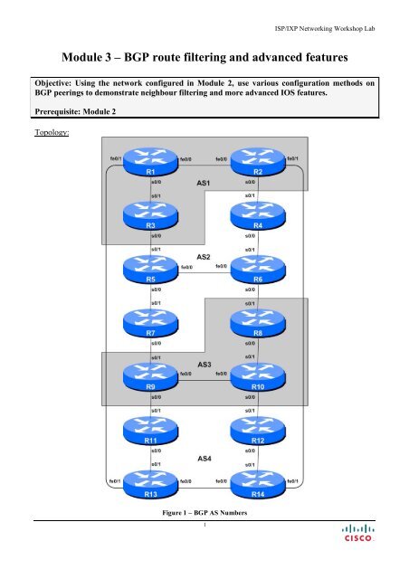
Topology:<br />
Figure 1 <strong>–</strong> <strong>BGP</strong> AS Numbers<br />
1
Wednesday, July 30, 2008<br />
Lab Notes<br />
The previous <strong>Module</strong> provided an introduction to setting up external <strong>BGP</strong>, but provided no way of<br />
controlling which networks are announced to which AS. The purpose of this module is to introduce<br />
the student to the types of routing policy which are available using <strong>BGP</strong>.<br />
In steps 4 to 9 we will configure each AS to become a non-transit AS, i.e. the AS won’t allow a<br />
connecting AS’s traffic to traverse it to reach another connecting AS. This will mean disconnectivity<br />
in the classroom <strong>–</strong> for example, AS3 will no longer be able to see any networks from AS1, etc. This is<br />
a deliberate policy to demonstrate the effectiveness of the <strong>BGP</strong> <strong>filtering</strong> being employed.<br />
In step 4 we achieve this by configuring an outgoing <strong>route</strong> filter to allow only local prefix(es) be sent<br />
to e<strong>BGP</strong> peers. At the same time, we also make sure that our peers only send us their own prefixes.<br />
We guarantee this by configuring an incoming filter. In general, it is good practice to configure filters<br />
in both directions to protect against misconfiguration at both ends of the peering. In step 6 we use AS-<br />
PATH filters. And in step 9 we make use of <strong>BGP</strong> communities to achieve the same effect.<br />
Important: each step must be carried out <strong>and</strong> completed by the whole workshop before the next step<br />
can be started. Do not immediately start the next step without receiving the go-ahead from the<br />
workshop instructors. If you do, it is likely the routing will break, <strong>and</strong> other <strong>route</strong>r teams may be<br />
unable to underst<strong>and</strong> the results of the configuration they are trying to implement.<br />
Important: retain the configuration used for <strong>Module</strong> 2.<br />
Lab Exercise<br />
1. Introduction to the <strong>BGP</strong> “next-hop-self” concept. Up to now we have made sure that OSPF<br />
includes a network statement for all external links in the network. While this is easy for<br />
consistency, quite often ISPs can forget to mark the external interface as passive, resulting in the<br />
<strong>route</strong>r attempting to set up adjacencies with other <strong>route</strong>rs outside the ASN. This is undesirable.<br />
The other problem is that the ISP’s IGP ends up with a large number of external point to point link<br />
subnets in it <strong>–</strong> this greatly reduces efficiency <strong>and</strong> scalability, especially in larger networks. This is<br />
where we introduce the next-hop-self <strong>BGP</strong> configuration. This changes the i<strong>BGP</strong> default by<br />
replacing the next-hop address for external sites from that of the external neighbour address to the<br />
loopback address of the local <strong>route</strong>r. The local <strong>route</strong>r knows how to get to the external destinations<br />
because it is connected to the LAN that leads there <strong>–</strong> the rest of the network internal to the AS is<br />
told simply to go via this <strong>route</strong>r. Note that because we do this, we no longer need to quote the<br />
external point to point link in our OSPF (or ISIS) configuration. For example:<br />
<strong>route</strong>r bgp 1234<br />
neighbor 1.2.3.4 next-hop-self<br />
Note that the use of next-hop-self on all i<strong>BGP</strong> sessions is considered industry best practice,<br />
<strong>and</strong> its use from now on in the workshop is strongly recommended.<br />
2. Converting each AS to use next-hop-self on i<strong>BGP</strong>. Each <strong>route</strong>r team should now modify the<br />
configuration of their IGP <strong>and</strong> i<strong>BGP</strong> so that they no longer carry external point to point links in<br />
Cisco Systems Inc 2<br />
170 West Tasman Drive.<br />
San Jose, CA 95134-1706<br />
Phone: +1 408 526-4000<br />
Fax: +1 408 536-4100
ISP/IXP Networking Workshop Lab<br />
IGP (be it OSPF or ISIS), but instead implement next-hop-self in i<strong>BGP</strong>. Here is an example for<br />
Router 3:<br />
(OSPF example)<br />
<strong>route</strong>r ospf 1<br />
no network 100.2.17.0 0.0.0.3 area 0<br />
! remove R3-R5 p2p link<br />
(ISIS example)<br />
interface serial 0/0<br />
no ip <strong>route</strong>r isis isp-as1 ! remove ISIS from R3-R5 p2p link<br />
(<strong>BGP</strong> example)<br />
<strong>route</strong>r bgp 1<br />
neighbor 100.1.15.224 next-hop-self<br />
neighbor 100.1.31.224 next-hop-self<br />
!<br />
The first step removes the external point to point link from OSPF; the second step removes the<br />
external point to point link from ISIS; the third sets up next-hop-self with each i<strong>BGP</strong> peer.<br />
3. Implement <strong>BGP</strong> policies. Before doing any configurations in this module it is important to note<br />
how to go about implementing <strong>BGP</strong> policies. Entering prefix lists, as-path filters or <strong>route</strong>-maps<br />
can be done at the CLI, but they only apply to <strong>BGP</strong> updates received after the policy configuration<br />
has been entered at the <strong>route</strong>r. This is because <strong>BGP</strong> sends incremental updates describing changes<br />
in <strong>route</strong>s announced or withdrawn. To apply the policy to the entire <strong>BGP</strong> routing table received<br />
from or sent to the peer, the <strong>BGP</strong> session needs to be “reset”. In older versions of IOS, this literally<br />
meant tearing down the <strong>BGP</strong> session, <strong>and</strong> then restoring it. However, as can be imagined, this<br />
causes severe stability issues on the service provider network, <strong>and</strong> ‘RFC2918: Route Refresh<br />
Capability’ has been added to most modern <strong>BGP</strong> implementations to allow graceful updates to<br />
<strong>BGP</strong> sessions when policy changes are required.<br />
To implement policy changes in any of the following worked examples, use the following <strong>route</strong>r<br />
comm<strong>and</strong>s, for example to implement new policy inbound <strong>and</strong> outbound on the peering between<br />
Router 1 <strong>and</strong> Router 13:<br />
Router1# clear ip bgp 100.1.2.2 out<br />
Router1# clear ip bgp 100.1.2.2 in<br />
Note: Do not forget the in <strong>and</strong> out subcomm<strong>and</strong>s in the above clear comm<strong>and</strong>s <strong>–</strong> omitting them<br />
will implement a hard reset of the <strong>BGP</strong> session. Review the <strong>BGP</strong> presentation if you don’t<br />
underst<strong>and</strong> why you do not want to ever do a hard reset on a <strong>BGP</strong> session.<br />
Checkpoint #1: call the lab assistant to verify the connectivity. Each <strong>route</strong>r team should check<br />
peerings to see the effect of this step. Use the “show ip bgp” comm<strong>and</strong> to show the <strong>BGP</strong> table <strong>–</strong><br />
ensure that the external prefixes learned by <strong>BGP</strong> now have a local next-hop address. Use the “trace”<br />
comm<strong>and</strong> to show that network connectivity is unaffected.<br />
STOP AND WAIT HERE<br />
3
Wednesday, July 30, 2008<br />
Filtering using prefix-lists<br />
4. Configure prefix filter based on network address: This step configures <strong>route</strong> prefix <strong>filtering</strong><br />
based on network address. This is done using prefix-lists, <strong>and</strong> is one method of controlling<br />
networks which are exchanged in <strong>BGP</strong> peerings. The aim here is to configure e<strong>BGP</strong> peerings so<br />
that only networks from neighbouring ASes are exchanged.<br />
Example: Router R13 (peering with R1)<br />
!<br />
ip prefix-list out-peer permit 100.4.0.0/18 le 32<br />
ip prefix-list out-peer deny 0.0.0.0/0 le 32<br />
!<br />
ip prefix-list in-peer permit 100.1.0.0/18 le 32<br />
ip prefix-list in-peer deny 0.0.0.0/0 le 32<br />
!<br />
<strong>route</strong>r bgp 4<br />
no synchronization<br />
network 100.4.32.0 mask 255.255.240.0<br />
neighbor 100.1.2.1 remote-as 1<br />
neighbor 100.1.2.1 description e<strong>BGP</strong> peering with Router1<br />
neighbor 100.1.2.1 prefix-list out-peer out<br />
neighbor 100.1.2.1 prefix-list in-peer in<br />
no auto-summary<br />
Example: Router R1 (peering with R13)<br />
!<br />
ip prefix-list out-peer permit 100.1.0.0/18 le 32<br />
ip prefix-list out-peer deny 0.0.0.0/0 le 32<br />
!<br />
ip prefix-list in-peer permit 100.4.0.0/18 le 32<br />
ip prefix-list in-peer deny 0.0.0.0/0 le 32<br />
!<br />
<strong>route</strong>r bgp 1<br />
no synchronization<br />
network 100.1.0.0 mask 255.255.240.0<br />
neighbor 100.1.2.2 remote-as 4<br />
neighbor 100.1.2.2 description Peering with Router13<br />
neighbor 100.1.2.2 prefix-list out-peer out<br />
neighbor 100.1.2.2 prefix-list in-peer in<br />
no auto-summary<br />
Note: an IOS prefix-list always has an implicit deny any as the last statement even though it is not<br />
listed in the configuration. Some ISPs add the implicit deny any as they consider it good practice<br />
<strong>and</strong> a security precaution.<br />
Note: these prefix-lists are only applied to peerings with other ASes. These are called external<br />
peerings (using e<strong>BGP</strong>). There is usually no need to apply such filters for i<strong>BGP</strong> peerings.<br />
Cisco Systems Inc 4<br />
170 West Tasman Drive.<br />
San Jose, CA 95134-1706<br />
Phone: +1 408 526-4000<br />
Fax: +1 408 536-4100
ISP/IXP Networking Workshop Lab<br />
Checkpoint #2: call the lab assistant to verify the connectivity. Each <strong>route</strong>r team should check<br />
peerings to see the effect of this step. Use the “show ip bgp neigh x.x.x.x advertise|<strong>route</strong>” comm<strong>and</strong>s.<br />
STOP AND WAIT HERE<br />
5. Perform Aggregation on the e<strong>BGP</strong> peerings. The previous step accepted the aggregate block<br />
<strong>and</strong> the sub-prefixes from the immediately adjacent ASes. Likewise, it announced all prefixes to<br />
the neighbouring ASes. Now modify the e<strong>BGP</strong> peering so that only the aggregate blocks are<br />
announced <strong>and</strong> accepted in the e<strong>BGP</strong> sessions.<br />
Example: Router R1 (peering with R13)<br />
!<br />
ip prefix-list out-peer permit 100.1.0.0/18<br />
ip prefix-list out-peer deny 0.0.0.0/0 le 32<br />
!<br />
ip prefix-list in-peer permit 100.4.0.0/18<br />
ip prefix-list in-peer deny 0.0.0.0/0 le 32<br />
!<br />
Note the subtle difference in the in-peer <strong>and</strong> out-peer prefix-lists in the example. The le 32 has<br />
been removed from the prefix-list configuration. This means that only an exact match of prefixlength<br />
will be allowed through the filters.<br />
Upon refresh of the <strong>BGP</strong> session, the sub-prefixes of the address blocks will disappear from the<br />
<strong>BGP</strong> table. This is the accepted way of applying <strong>filtering</strong> to an e<strong>BGP</strong> session.<br />
STOP AND WAIT HERE<br />
6. Remove configuration from previous example. This step will demonstrate how to remove the<br />
configuration entered in the previous example. This is essential before we move onto the next step.<br />
Example: Router R1<br />
Router1#conf t<br />
Router1(config)#<strong>route</strong>r bgp 1<br />
!<br />
5
Wednesday, July 30, 2008<br />
! First remove prefix list from <strong>BGP</strong> peering with R13<br />
!<br />
Router1(config-<strong>route</strong>r)#no neighbor 100.1.2.2 prefix-list out-peer out<br />
Router1(config-<strong>route</strong>r)#no neighbor 100.1.2.2 prefix-list in-peer in<br />
!<br />
! Now remove the prefix-lists themselves<br />
!<br />
Router1(config)#no ip prefix-list out-peer<br />
Router1(config)#no ip prefix-list in-peer<br />
!<br />
! That’s the configuration nice <strong>and</strong> tidy, the way it should be.<br />
!<br />
Router1(config)#end<br />
!<br />
! Now clear the bgp peering so that the old policy is removed<br />
!<br />
Router1#clear ip bgp 100.1.2.2 out<br />
Router1#clear ip bgp 100.1.2.2 in<br />
Router1#<br />
AS-PATH filters<br />
7. Configure prefix filter based on AS path attribute: This step configures <strong>route</strong> prefix <strong>filtering</strong><br />
based on AS path. This is done using AS path access-lists, <strong>and</strong> is another method of controlling<br />
networks which are exchanged in <strong>BGP</strong> peerings.<br />
Outgoing direction example <strong>–</strong> Router R13<br />
ip as-path access-list 2 permit ^$<br />
ip as-path access-list 3 permit ^1$<br />
!<br />
<strong>route</strong>r bgp 4<br />
neighbor 100.1.2.1 remote-as 1<br />
neighbor 100.1.2.1 filter-list 2 out<br />
neighbor 100.1.2.1 filter-list 3 in<br />
Incoming direction example <strong>–</strong> Router R1<br />
ip as-path access-list 2 permit ^$<br />
ip as-path access-list 3 permit ^4$<br />
!<br />
<strong>route</strong>r bgp 1<br />
neighbor 100.1.2.2 remote-as 4<br />
neighbor 100.1.2.2 filter-list 2 out<br />
neighbor 100.1.2.2 filter-list 3 in<br />
Q. Why does the outbound filter list match the null as-path <strong>and</strong> not the local AS number in the<br />
above examples?<br />
A. Because the AS-PATH attribute is set after the prefix lists, as-path filters <strong>and</strong> <strong>route</strong>-maps. If the<br />
local AS was included in the outbound filter-list configuration, the prefixes would be ignored as<br />
their AS-PATH attribute would not be set at that stage.<br />
Cisco Systems Inc 6<br />
170 West Tasman Drive.<br />
San Jose, CA 95134-1706<br />
Phone: +1 408 526-4000<br />
Fax: +1 408 536-4100
ISP/IXP Networking Workshop Lab<br />
To verify that the regular expression works as intended, use the EXEC comm<strong>and</strong> “show ip bgp<br />
regexp ” to display all the paths that match the specified regular expression.<br />
Don’t forget that the comm<strong>and</strong> clear ip bgp [in|out] is required to<br />
implement this filter.<br />
Checkpoint #3: call the lab assistant to verify the connectivity. Once the lab instructor gives the class<br />
the gohead, remove the attribute <strong>and</strong> filter list configuration <strong>and</strong> move on to the next step.<br />
STOP AND WAIT HERE<br />
8. Remove the configuration from the previous example. This step will demonstrate how to<br />
remove the configuration entered in the previous example. This is essential before we move onto<br />
the next step.<br />
Example: Router 1<br />
Router1#conf t<br />
Router1(config)#<strong>route</strong>r bgp 1<br />
!<br />
! First remove the filter list from <strong>BGP</strong> peering with R13<br />
!<br />
Router1(config-<strong>route</strong>r)#no neighbor 100.1.2.2 filter-list 2 out<br />
Router1(config-<strong>route</strong>r)#no neighbor 100.1.2.2 filter-list 3 in<br />
!<br />
! Now remove the filter lists themselves<br />
!<br />
Router1(config)#no ip as-path access-list 2<br />
Router1(config)#no ip as-path access-list 3<br />
!<br />
! That’s the configuration nice <strong>and</strong> tidy, the way it should be.<br />
!<br />
Router1(config)#end<br />
!<br />
! Now clear the bgp peering so that the old policy is removed<br />
!<br />
Router1#clear ip bgp 100.1.2.2 in<br />
Router1#clear ip bgp 100.1.2.2 out<br />
Router1#<br />
7
Wednesday, July 30, 2008<br />
<strong>BGP</strong> Communities for <strong>filtering</strong> (<strong>and</strong> <strong>route</strong>-maps)<br />
9. Introduction to <strong>BGP</strong> communities <strong>and</strong> <strong>route</strong>-maps: This step introduces the Router Teams to<br />
using <strong>BGP</strong> communities for tagging, identifying, <strong>and</strong> eventually <strong>filtering</strong> prefixes. We achieve<br />
similar end results to what we achieved in the previous steps using prefix-list <strong>and</strong> as-path filters.<br />
On all <strong>route</strong>rs, configure <strong>BGP</strong> to send a community for all prefixes belonging to the local AS<br />
advertised to external <strong>BGP</strong> peers. The community should be in the form of [AS number]:[Router<br />
number]. For example, Router9 should use community 3:9.<br />
Example on Router R9:<br />
ip bgp-community new-format<br />
! needed so that a community is treated in 16-bit:16-bit format<br />
! rather than one 32-bit integer.<br />
!<br />
ip prefix-list out-match permit 100.3.0.0/18 le 32<br />
!<br />
<strong>route</strong>-map outfilter permit 10<br />
match ip address prefix-list out-match<br />
set community 3:9<br />
!<br />
<strong>route</strong>r bgp 3<br />
neighbor x.x.x.x remote-as ASN<br />
neighbor x.x.x.x <strong>route</strong>-map outfilter out<br />
neighbor x.x.x.x send-community<br />
Note:<br />
1) A community attribute can be seen in the <strong>BGP</strong> table via show ip bgp comm<strong>and</strong>.<br />
2) A community attribute is a 32-bit field. By IETF agreed-upon convention it is divided into two<br />
16-bit fields for easy interpretation. The top 16-bit contains the AS number, while the lower<br />
16-bit represents an integer that has specific meaning to the two ASes involved in the peering.<br />
The exceptions to this are the well-known community attribute strings such as no-export or<br />
local-as.<br />
Q: Why is send-community needed for e<strong>BGP</strong> peerings?<br />
A: As community values are not passed by default between <strong>BGP</strong> peers, you need to tell the <strong>route</strong>r<br />
explicitly to do this.<br />
Checkpoint #4: call the lab assistant to verify the connectivity. Each <strong>route</strong>r team should again check<br />
their peerings to see what the effect is this time.<br />
STOP AND WAIT HERE<br />
10. Remove the configuration from the previous example. This step will demonstrate how to<br />
remove the configuration entered in the previous example. This is essential before we move onto<br />
the next step.<br />
Cisco Systems Inc 8<br />
170 West Tasman Drive.<br />
San Jose, CA 95134-1706<br />
Phone: +1 408 526-4000<br />
Fax: +1 408 536-4100
ISP/IXP Networking Workshop Lab<br />
Example: Router 9<br />
Router9#conf t<br />
Router9(config)#<strong>route</strong>r bgp 3<br />
!<br />
! First remove the <strong>route</strong>-map from the e<strong>BGP</strong> peering<br />
!<br />
Router9(config-<strong>route</strong>r)#no neighbor x.x.x.x <strong>route</strong>-map outfilter out<br />
!<br />
! Now remove the <strong>route</strong>-map itself<br />
!<br />
Router9(config)#no <strong>route</strong>-map outfilter<br />
!<br />
! And now remove the prefix-list used by the <strong>route</strong>-map<br />
!<br />
Router9(config)#no ip prefix-list out-match<br />
!<br />
! That’s the configuration nice <strong>and</strong> tidy, the way it should be.<br />
!<br />
Router9(config)#end<br />
!<br />
! Now clear the bgp peering so that the old policy is removed<br />
!<br />
Router9#clear ip bgp x.x.x.x out<br />
Router9#<br />
<strong>BGP</strong> Communities<br />
11. Setting <strong>BGP</strong> Communities. In step 9 the community a network belongs to was generated at the<br />
point where one <strong>BGP</strong> <strong>route</strong>r spoke to another <strong>BGP</strong> <strong>route</strong>r. While this situation is valuable in<br />
demonstrating how to set communities, the more common scenario is where an ISP attaches a<br />
community to a network when the network is injected into the <strong>BGP</strong> routing table.<br />
Each <strong>route</strong>r team should assign a community to the network block they have been allocated in<br />
<strong>Module</strong> 1. Review the <strong>BGP</strong> documentation to find out how to do this. Each <strong>route</strong>r should set a<br />
community of format [AS number]:[Router number] exactly as in the previous step.<br />
Example for Router R1:<br />
ip bgp-community new-format<br />
!<br />
<strong>route</strong>-map community-tag permit 10<br />
set community 1:1<br />
!<br />
<strong>route</strong>r bgp 1<br />
no synchronization<br />
network 100.1.0.0 mask 255.255.240.0 <strong>route</strong>-map community-tag<br />
neighbor 100.1.2.2 remote-as 4<br />
neighbor 100.1.2.2 send-community<br />
no auto-summary<br />
!<br />
ip <strong>route</strong> 100.1.0.0 255.255.240.0 null0<br />
Check that the network appears with its community in the <strong>BGP</strong> routing table.<br />
9
Wednesday, July 30, 2008<br />
Q: Why do your external, but not your internal, peers see the community set on the network?<br />
A: See earlier. All peerings require the <strong>BGP</strong> send-community subcomm<strong>and</strong> for the community<br />
attribute to be sent between <strong>BGP</strong> peers.<br />
12. Communities on internal <strong>BGP</strong> peerings. Following on from the previous step, now set up the<br />
internal peerings so that the community attribute for your network is sent to local peers.<br />
Hint: to do this, simply add in the configuration line neighbor x.x.x.x send-community for all i<strong>BGP</strong><br />
peerings. Don’t forget to refresh the <strong>BGP</strong> peering sessions so that the configuration change can be<br />
implemented.<br />
Checkpoint #5: call the lab assistant <strong>and</strong> demonstrate how the community has been set for your<br />
network using the “show ip bgp” comm<strong>and</strong>s. Also, demonstrate that you can see the communities set<br />
by your internal <strong>and</strong> external <strong>BGP</strong> peers.<br />
13. Configure incoming prefix filter based on community attribute. The aim here is to only accept<br />
networks which are received from the neighbouring external <strong>BGP</strong> peer. (This is similar to what<br />
was being attempted in Steps 4 <strong>and</strong> 7 with prefix <strong>and</strong> AS path <strong>filtering</strong>.) For example, R13 should<br />
only accept the network originated by R1, <strong>and</strong> should use the knowledge of the community R1 has<br />
attached to the network to achieve this.<br />
Example on Router R13:<br />
<strong>route</strong>-map infilter permit 10<br />
match community <br />
!<br />
ip community-list permit 1:1<br />
!<br />
<strong>route</strong>r bgp 4<br />
neighbor 100.1.2.1 <strong>route</strong>-map infilter in<br />
The choice is up to each <strong>route</strong>r team <strong>–</strong> it is not announced in any <strong>BGP</strong><br />
peering or used in any other way apart from identifying the community-list (compare with the<br />
access-list number).<br />
14. Set local-preference attribute on received e<strong>BGP</strong> <strong>route</strong>s. In this example, local preference will<br />
be set on the <strong>route</strong>s matching the community filter in Step 13. Retain the <strong>route</strong>-map used in Step<br />
13 <strong>–</strong> an additional configuration line will be added to it. You also want to allow the other networks<br />
heard through the filters with the local-preference set to the default value.<br />
Q. Why?<br />
A. Without the second permit directive the <strong>route</strong>-map implements a default deny <strong>and</strong> no other<br />
prefixes will be passed through.<br />
Example:<br />
<strong>route</strong>-map infilter permit 10<br />
set local-preference 120<br />
!<br />
<strong>route</strong>-map infilter permit 20<br />
Cisco Systems Inc 10<br />
170 West Tasman Drive.<br />
San Jose, CA 95134-1706<br />
Phone: +1 408 526-4000<br />
Fax: +1 408 536-4100
ISP/IXP Networking Workshop Lab<br />
Note that after a new policy is set, <strong>BGP</strong> session needs to be refreshed so that the new policy can<br />
then be applied. The <strong>route</strong>r does not automatically keep all the updates it ever received from the<br />
peer so this is necessary. This is done by using “clear ip bgp in” exec comm<strong>and</strong>.<br />
Checkpoint #6: call the lab assistant <strong>and</strong> demonstrate how the <strong>route</strong>s originated by your e<strong>BGP</strong> peers<br />
now have local preference set to 120. Also show how other <strong>route</strong>s have the default local preference of<br />
100.<br />
<strong>BGP</strong> Peer-Groups<br />
15. Configure the peer-group feature for i<strong>BGP</strong> peers. <strong>BGP</strong> peer-groups help reduce the <strong>route</strong>r<br />
processor load in generating <strong>and</strong> sending updates to peers which have the same policy. This step<br />
configures <strong>BGP</strong> peer-groups for the i<strong>BGP</strong> peers in each AS. Replace the individual configuration<br />
for each i<strong>BGP</strong> peer with a peer-group configuration, as given in the example below.<br />
Example for Router R9:<br />
<strong>route</strong>r bgp 3<br />
neighbor ibgp-peers peer-group<br />
neighbor ibgp-peers description Peer-Group used for all i<strong>BGP</strong> peers<br />
neighbor ibgp-peers remote-as 3<br />
neighbor ibgp-peers update-source loopback 0<br />
neighbor ibgp-peers send-community<br />
neighbot ibgp-peers next-hop-self<br />
neighbor ibgp-peers password cisco<br />
Note: the old pre-peer-group configuration must be removed before converting from non-peergroup<br />
configuration to using peer-groups.<br />
<strong>route</strong>r bgp 3<br />
no neighbor 100.3.15.224<br />
no neighbor 100.3.63.224<br />
!<br />
neighbor 100.3.15.224 peer-group ibgp-peers<br />
neighbor 100.3.63.224 peer-group ibgp-peers<br />
Q: What are the advantages of using peer-groups?<br />
A: <strong>BGP</strong> peer groups allow a common configuration to be used for several <strong>BGP</strong> peers. The most<br />
common application is for i<strong>BGP</strong>. All internal <strong>BGP</strong> peers in an ISP network tend to have the same<br />
relationship with each other. Rather than having a substantial configuration per peer, <strong>and</strong> having to<br />
change every peering when details need to be changed, the configuration can be put in a peergroup,<br />
<strong>and</strong> only the peer group has to be changed to alter the peering configuration for all i<strong>BGP</strong><br />
peers. This substantially reduces the work overhead required in making changes, the <strong>route</strong>r CPU<br />
for processing, <strong>and</strong> significantly cleans up the configuration to view.<br />
It is strongly recommended that the peer-group subcomm<strong>and</strong> be the “default” way of configuring<br />
all <strong>BGP</strong> peers. As was stated before, most i<strong>BGP</strong> peers have the same configuration, so it is of great<br />
benefit to the <strong>route</strong>r, the operations staff, <strong>and</strong> network engineering staff to simplify the<br />
11
Wednesday, July 30, 2008<br />
configurations wherever possible. Besides, a configuration which makes extensive use of peergroups<br />
is usually much easier to read than one which has distinct configuration per peer, especially<br />
in networks with large numbers of peers.<br />
Note: Wherever <strong>BGP</strong> is configured in future in the workshop, it is expected that peer-groups<br />
will be used as part of the <strong>BGP</strong> configuration (<strong>and</strong> most definitely for any i<strong>BGP</strong><br />
configuration).<br />
16. Summary: This module has introduced some of the basic <strong>features</strong> available to configure <strong>BGP</strong><br />
peerings in Cisco IOS. The reader is encouraged to try further permutations of the configuration<br />
examples given here. Community usage is gaining in popularity as the feature is now recognised to<br />
give considerable advantages in controlling routing policy between different ASes. Route refresh<br />
<strong>and</strong> peer-groups are also widely used in ISP backbones as they considerably ease administration<br />
<strong>and</strong> configuration of an operational network.<br />
Cisco Systems Inc 12<br />
170 West Tasman Drive.<br />
San Jose, CA 95134-1706<br />
Phone: +1 408 526-4000<br />
Fax: +1 408 536-4100
ISP/IXP Networking Workshop Lab<br />
Review Questions:<br />
1. Why is making use of Route Refresh the best way of implementing new <strong>BGP</strong> policy?<br />
2. Why do AS-PATH filters provide less granularity then prefix-filters for <strong>filtering</strong> a <strong>BGP</strong><br />
session? And which is preferred in an ISP network, <strong>and</strong> why?<br />
3. When should the community attribute be set on a <strong>BGP</strong> prefix?<br />
4. Does IOS send <strong>BGP</strong> communities by default for i<strong>BGP</strong>? For e<strong>BGP</strong>? If not, what must operators<br />
remember to do?<br />
13
Wednesday, July 30, 2008<br />
CONFIGURATION NOTES<br />
Documentation is critical! You should record the configuration at each Checkpoint, as well as the<br />
configuration at the end of the module.<br />
Cisco Systems Inc 14<br />
170 West Tasman Drive.<br />
San Jose, CA 95134-1706<br />
Phone: +1 408 526-4000<br />
Fax: +1 408 536-4100