APPLICATION NOTE: Installing a Net2 control unit - IP Way
APPLICATION NOTE: Installing a Net2 control unit - IP Way
APPLICATION NOTE: Installing a Net2 control unit - IP Way

You also want an ePaper? Increase the reach of your titles
YUMPU automatically turns print PDFs into web optimized ePapers that Google loves.
30/10/2006<br />
AN1012 - <strong>Installing</strong> a <strong>Net2</strong> <strong>control</strong> <strong>unit</strong><br />
Paxton Access<br />
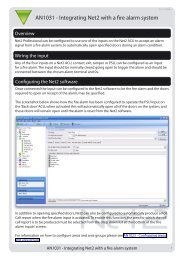
<strong>Net2</strong> <strong>control</strong> <strong>unit</strong> installation<br />
The correct installation of <strong>Net2</strong> <strong>control</strong> <strong>unit</strong>s (ACU’s) is essential to the success of the system. A fault<br />
introduced at the early stages of installation can cause delays later in the project.<br />
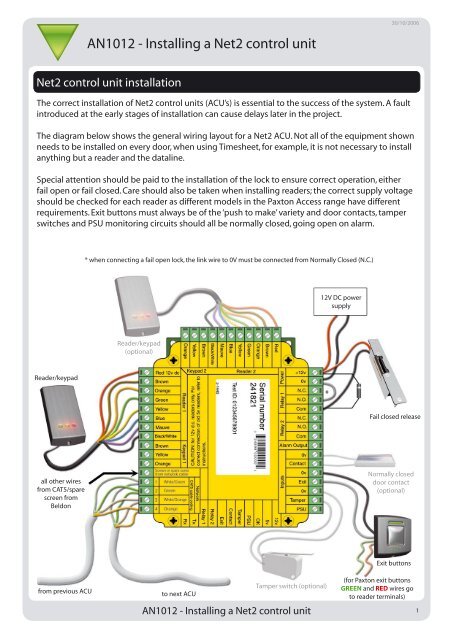
The diagram below shows the general wiring layout for a <strong>Net2</strong> ACU. Not all of the equipment shown<br />
needs to be installed on every door, when using Timesheet, for example, it is not necessary to install<br />
anything but a reader and the dataline.<br />
Special attention should be paid to the installation of the lock to ensure correct operation, either<br />
fail open or fail closed. Care should also be taken when installing readers; the correct supply voltage<br />
should be checked for each reader as different models in the Paxton Access range have different<br />
requirements. Exit buttons must always be of the ‘push to make’ variety and door contacts, tamper<br />
switches and PSU monitoring circuits should all be normally closed, going open on alarm.<br />
* when connecting a fail open lock, the link wire to 0V must be connected from Normally Closed (N.C.)<br />
12V DC power<br />
supply<br />
Reader/keypad<br />
(optional)<br />
Reader/keypad<br />
*<br />
Fail closed release<br />
all other wires<br />
from CAT5/spare<br />
screen from<br />
Beldon<br />
Normally closed<br />
door contact<br />
(optional)<br />
Exit buttons<br />
from previous ACU<br />
to next ACU<br />
<strong>Net2</strong><br />
V4<br />
Tamper switch (optional)<br />
AN1012 - <strong>Installing</strong> a <strong>Net2</strong> <strong>control</strong> <strong>unit</strong><br />
(for Paxton exit buttons<br />
GREEN and RED wires go<br />
to reader terminals)<br />
1
Dataline connection<br />
By far the most common cause of problems, with <strong>Net2</strong> installations, is incorrect wiring of the<br />
dataline. It is extremely important that the following simple rules are followed for each <strong>control</strong>ler on<br />
the line and that the line is terminated correctly.<br />
For full details of the dataline refer to AN1040 - <strong>Installing</strong> the <strong>Net2</strong> dataline.<br />
The dataline must loop in and out of each <strong>control</strong>ler using the same coloured cores for each <strong>unit</strong>; CAT5 colour<br />
codes are shown on the <strong>control</strong>ler’s wiring label. The <strong>control</strong>lers must be installed in one continuous ‘daisy’<br />
chain with termination resistors installed at each end.<br />
Any spare cores and the cable screen must be connected to the network screen terminal; this provides a<br />
common reference for all of the <strong>control</strong>lers on the dataline.<br />
A single 120-ohm resistor should be wired across each data pair at either end of the dataline, a total of four<br />
resistors should be fitted. One between Orange-white and Orange, and one between Green-white and Green,<br />
at each end of the line. If the PC is fitted in the middle of the dataline a termination should not be fitted at<br />
the RS232-485 converter, only at the two end ACUs<br />
When using 12V readers<br />
12V readers are wired into the appropriate coloured terminals on the <strong>control</strong>ler’s reader port.<br />
When using 5V readers<br />
For systems where 5V readers are to be used, readers must not be connected to yellow label <strong>control</strong>lers until the jumper<br />
setting has been changed on the <strong>control</strong>ler PCB. The jumpers on <strong>Net2</strong> <strong>control</strong>lers can be found under the wiring label.<br />
Once the jumper is changed to the 5V position the reader can be wired colour to colour but the ‘Red’ terminal will now<br />
output 5V.<br />
Installation of a <strong>Net2</strong> ACU in a metal PSU enclosure<br />
The best way to install a <strong>Net2</strong> ACU is in the specially designed Paxton metal power supply enclosure.<br />
This <strong>unit</strong> contains a <strong>Net2</strong> ACU, a 2A 12V d.c. power supply, with an output in the event of mains<br />
failure. A charging circuit for the addition of battery back up and an enclosure tamper switch.<br />
The diagram below shows the arrangement of an ACU installed in the enclosure.<br />
Alarm messages will be reported to the <strong>Net2</strong><br />
<strong>Net2</strong><br />
server if, the lid of the ACU is opened (tamper) or if the<br />
mains supply to the <strong>unit</strong> fails (this alarm will only work successfully if battery back up is fitted).<br />
V4<br />
AN1012 - <strong>Installing</strong> a <strong>Net2</strong> <strong>control</strong> <strong>unit</strong><br />
2
z-1440<br />
Test ID: 012345678901<br />
<br />
Serial number<br />
241821<br />
<br />
<br />
<br />
<br />
<br />
<br />
<br />
<br />
<br />
<br />
<br />
<br />
<br />
<br />
<br />
<br />
<br />
<br />
<br />
<br />
<br />
<br />
<br />
<br />
<br />
<br />
<br />
<br />
<br />
<br />
<br />
<br />
<br />
<br />
<br />
<br />
<br />
<br />
<br />
<br />
Sealed Rechargeable<br />
Battery<br />
POWER<br />
PSSONIC<br />
12V 1.2Ah<br />
<strong>Net2</strong><br />
V4<br />
AN1012 - <strong>Installing</strong> a <strong>Net2</strong> <strong>control</strong> <strong>unit</strong><br />
3