Zelio Control - Farnell
Zelio Control - Farnell
Zelio Control - Farnell

You also want an ePaper? Increase the reach of your titles
YUMPU automatically turns print PDFs into web optimized ePapers that Google loves.
EDMS xxxxxxxxx 03 2009<br />
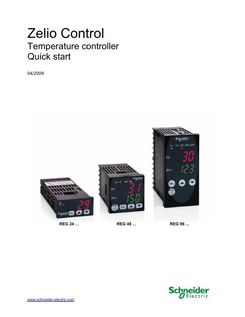
<strong>Zelio</strong> <strong>Control</strong><br />
Temperature controller<br />
Quick start<br />
04/2009<br />
www.schneider-electric.com<br />
REG 24 ... REG 48 ... REG 96 ...
Schneider Electric assumes no responsibility for any errors that may appear in this document. If you have any suggestions<br />
for improvements or amendments or have found errors in this publication, please notify us.<br />
No part of this document may be reproduced in any form or by any means, electronic or mechanical, including photocopying,<br />
without express written permission of Schneider Electric.<br />
All pertinent state, regional, and local safety regulations must be observed when installing and using this product. For<br />
reasons of safety and to help ensure compliance with documented system data, only the manufacturer should perform<br />
repairs to components.<br />
When devices are used for applications with technical safety requirements, the relevant instructions must be followed.<br />
Failure to use Schneider Electric software or approved software with our hardware products may result in injury, harm, or<br />
improper operating results.<br />
Failure to observe this information can result in injury or equipment damage.<br />
© 2009 Schneider Electric. All rights reserved.<br />
2 EIO0000000377 00 04/2009
SOMMAIRE<br />
SOMMAIRE......................................................................................................................................... 3<br />
CHAPTER 1 INTRODUCTION ............................................................................................................ 5<br />
Fonctioning: ................................................................................................................................... 5<br />
Application examples: ................................................................................................................... 5<br />
Identification and functionnalities: Chapter 1 Introduction ..................................................... 6<br />
CHAPTER 2 : TERMINOLOGY........................................................................................................... 7<br />
PID : Proportionnel Intégral Dérivé :............................................................................................. 7<br />
The outputs: ................................................................................................................................... 8<br />
Regulation principle: ..................................................................................................................... 9<br />
CHAPTER 3: EXAMPLES OF INTEGRATED FUNCTIONS INTO THE CONTROLLERS................ 11<br />
Auto tunning: ............................................................................................................................... 11<br />
Fuzzy logic: .................................................................................................................................. 11<br />
Self control :................................................................................................................................. 11<br />
Ramps: Chapter 3 Example of functions................................................................................ 12<br />
Pid 2 :............................................................................................................................................ 12<br />
Soft start :..................................................................................................................................... 12<br />
Alarms: ......................................................................................................................................... 12<br />
CHAPTER 4 : WIRING AND SCHEMATICS :................................................................................... 13<br />
REG 24 (12 models) : .................................................................................................................. 13<br />
REG 48 (14 models) : ................................................................................................................... 13<br />
REG 96 (14 models): Chapter 4 wiring and shematics ........................................................... 14<br />
CHAPTER 5: IMPLEMENTATION .................................................................................................... 15<br />
Selection guide: ........................................................................................................................... 15<br />
Front face description : Chapter 5 Implementation ............................................................... 16<br />
CHAPTER 6: EXAMPLE OF IMPLEMENTATION ............................................................................ 17<br />
1 st step : <strong>Control</strong>ler selection.................................................................................................... 17<br />
2sd step : The cabling ................................................................................................................. 17<br />
3 Rd step : Front face programming Chapter 6 Example of implementation ....................... 18<br />
Probe type setting (PT100) .......................................................................................................... 18<br />
Setting of the PT100 probe range (0 to 400°C)...... ..................................................................... 19<br />
Setting of the minimum value for the PT100 probe Pvb = 0°C............................................ ...... 19<br />
Setting of the maximum value for the PT100 probe PvF = 400°C .......................................... ... 19<br />
Chapter 6 Example of implementation ....................................................................................... 20<br />
Setting of the choosen decimal value (Pvd) (to display the tenth)........................................... 20<br />
Chapter 6 Example of implementation ....................................................................................... 21<br />
Regulation mode selection = heating on channel 1 (rEv).......................................................... 21<br />
Alarms 1 and 2 parameters setting............................................................................................. 21<br />
Alarm 1 parameters setting at 32°C Chapter 6 Example of implementation ......................... 22<br />
Alarm 2 setting at 38°C............................ .................................................................................... 22<br />
Parameter setting of the alarms on high overtaking (do1T) ..................................................... 22<br />
4 Th step: Functional test............................................................................................................ 23<br />
1 St step: install the software <strong>Zelio</strong><strong>Control</strong> Soft (compatible with Windows XP and Vista) ... 23<br />
2 Nd step: installation of the TSXCUSB485 driver..................................................................... 23<br />
3 Rd step: connect the TSXUSB485 to your PC and the controller.......................................... 23<br />
4 Th step : check the communication port parameters of the TSXCUSB485 driver................ 24<br />
5 Th step: Discover the software <strong>Zelio</strong><strong>Control</strong> Soft................................................................... 24<br />
Chapter 6 Example of implementation ....................................................................................... 25<br />
6 Th step: check the communication parameters of the TSXCUSB485 driver......................... 25<br />
7 Th step: Communication parameters setting:......................................................................... 25<br />
Chapter 6 Setup example ............................................................................................................ 26<br />
8 Th step: Connection to the régulator and application Upload ............................................... 26<br />
9 Th step: Application display .................................................................................................... 26<br />
CHAPITRE 7: <strong>Zelio</strong><strong>Control</strong> SOFT software .................................................................................... 27<br />
<strong>Zelio</strong><strong>Control</strong> Soft screen - oPE CH1 ........................................................................................... 27<br />
EIO0000000377 00 04/2009 3
<strong>Zelio</strong><strong>Control</strong> SOFT screen PID CH2 ............................................................................................ 27<br />
<strong>Zelio</strong><strong>Control</strong> SOFT screen PID CH2 ............................................................................................ 28<br />
<strong>Zelio</strong><strong>Control</strong> Soft screen - PLT CH3............................................................................................ 29<br />
<strong>Zelio</strong><strong>Control</strong> Soft screen - PRG CH4........................................................................................... 30<br />
<strong>Zelio</strong><strong>Control</strong> Soft screen - MON Ch5.......................................................................................... 31<br />
<strong>Zelio</strong><strong>Control</strong> Soft screen – SET Ch6 ........................................................................................... 32<br />
<strong>Zelio</strong><strong>Control</strong> Soft screen – SyS Ch7 ........................................................................................... 33<br />
<strong>Zelio</strong><strong>Control</strong> Soft screen – ALM Ch8 .......................................................................................... 34<br />
<strong>Zelio</strong><strong>Control</strong> Soft screen - CoM CH9........................................................................................... 35<br />
<strong>Zelio</strong><strong>Control</strong> Soft screen - PFb CH10.......................................................................................... 35<br />
<strong>Zelio</strong><strong>Control</strong> Soft screen - PAS CH11 ......................................................................................... 36<br />
<strong>Zelio</strong><strong>Control</strong> Soft screen - CFG CH13......................................................................................... 37<br />
Application file saving under <strong>Zelio</strong><strong>Control</strong> SOFT ...................................................................... 38<br />
4 EIO0000000377 00 04/2009
CHAPTER 1 INTRODUCTION<br />
Fonctioning:<br />
The temperature control relays are equiped with a sensor input that permits to use multiple types of<br />
sensors (PT100 probe, thermocouple, current or voltage sensors depending the model), one or two<br />
process outputs (relay, solid state relay interface or analog) for heating, cooling or heating and<br />
cooling regulation based on PID algorithm.<br />
The measured temperature and the setpoint can be displayed in °Celsius or °Fahrenheit.<br />
Advanced functions are embedded: Ramps (up to 16), hysteresis, fuzzy logic, auto tuning, soft<br />
start, alarms.<br />
The temperature controllers can be setup using the front face interface or through a common<br />
software by a communication port and the integrated Modbus.<br />
This communication port provides intergartion capability in an itelligente architecture supervised by<br />
Magelis terminal or controled by PLCs(Twido, M340 or Premium) to exchange setpoints, process<br />
values and alarms.<br />
Application examples:<br />
The temperature controllers Zélio control REG provide a solution for temperature control in the<br />
following applications:<br />
- Ovens and furnaces,<br />
- Extrusion lines,<br />
- Plastic and rubber presses,<br />
- thermo-forming,<br />
- Production of synthetic fibres an polymerisation,<br />
- Food and drink processing lines,<br />
- Moulding presses,<br />
- Environmental chambers, overhead furnaces and test benches,<br />
- UV &laser technologies,<br />
- Cabin of painting,<br />
- Cold rooms,<br />
- Horticultural and livestock farms,<br />
- Maintening the temperature of a colour bath…<br />
EIO0000000377 00 04/2009 5
Identification and functionnalities: Chapter 1 Introduction<br />
The product part number allows identification of the embedded functions:<br />
24 controllers :<br />
REG 24 P TP 1 A R HU<br />
P UJ L LU<br />
J<br />
Regulator Size PID Input Output Without Output power<br />
type number modbus type supply<br />
P = PID<br />
Input type: TP = Thermocouples and PT100<br />
UJ = Analog signal<br />
Modbus function: A = no modbus available<br />
Output type: R = relay<br />
L = solid state relay interface<br />
J = analog (4/20mA)<br />
Power supply: HU = 110/220 VAC<br />
LU = 24 V AC/DC<br />
48/96 controllers :<br />
REG 48 P UN 1 L R HU<br />
96 2 L LU<br />
J<br />
Regulator Size PID Input Output Without Output Power<br />
type number modbus type supply<br />
P = PID<br />
Input type: UN = universal input thermocouple / PT100 / analog<br />
Output type: R = relay<br />
L = solid state relay interface<br />
J = analog (4/20mA)<br />
Modbus function: L = no modbus available<br />
Power supply : HU = 110/220 VAC<br />
LU = 24 V AC/DC<br />
Note : When 2 outputs possible combination between 1 relay and 1 solid state relay interface or 1<br />
solid state relay and one current (for detail see doc 24480-EN page 6)<br />
6 EIO0000000377 00 04/2009
CHAPTER 2 : TERMINOLOGY<br />
PID : Proportionnel Intégral Dérivé :<br />
The principle of the PID algorithm consists on 3 actions that are dependant to the difference<br />
between the setpoint (SV) and the measured process value (PV).<br />
- A proportional action ne action proportionnelle, the error is multiplied by a gain GR<br />
- A complete action, the error is integrated on an interval of time TI<br />
- Derivated action, the error is derivated according to time TD<br />
Consigne<br />
SetPoint (SP)<br />
PID principle schematic<br />
The parameters of the PID influence the answer of the system in the following way:<br />
- When the proportional gain GR increases, the time of rise is shorter but there is a more<br />
important overshoot of the setpoint. The time of stabilization varies little and the static error is<br />
improved.<br />
- When 1 / TI increase, the time of rise is shorter, but there is a more important overtaking of the<br />
setpoint. The time of stabilization stretches out but we assure a static no error.<br />
- When TD increases, the time of rise changes little, but the overshoot decreases. The time of<br />
stabilization is better and there is no influence on the static error.<br />
Introduction<br />
EDMS xxxxxxxxx 03 2009<br />
The use of 24/48/96 controllers is going to allow through a parameter setting of variables to appeal<br />
to automatic functions or manual regulations.<br />
These variables are going to allow:<br />
+<br />
-<br />
Gr<br />
1/Ti<br />
Td<br />
Mesure<br />
Process value (PV)<br />
Process<br />
- To choose the type of sensor used (probe thermocouple or PT100, analogical sensor),<br />
- To choose the type of output used according to the actuator(s) (relay, solid state relay,<br />
analogical),<br />
- To choose the function of regulation (heating or cooling or heating and cooling),<br />
- To reduce the time of establishment (the value of measure reaches as quickly as possible the<br />
setpoint),<br />
- Avoid overshoot (fuzzy logic and PID2),<br />
- To maintain the temperature very close to the setpoint (réduction of the hysteresis and the dead<br />
band),<br />
- Avoid influence of perturbation,<br />
- To activate alarms (high, low, delayed…),<br />
- Setup ramps (up to 16 depending the model) to chain cycles of regulations,<br />
- To have information of defects (overflowing measures, defect sensors),<br />
- To lock or authorize the modification of the parameters from the front face of the product.<br />
EIO0000000377 00 04/2009 7
The outputs:<br />
Chapter 2 Terminology<br />
- Relay : Output type mostly used<br />
- Solid state relay interface: Used to contrôle actuator with no noise or frequent switching.<br />
- Courant : used to drive analog actuator such as speed drives<br />
On and OFF control: Most simple algorithm, no anticipation of the setpoint, not precized, we notice<br />
a lot of oscillations.<br />
Proportional control: The process output is proportional to the derivation from the. The<br />
proportional band allows overshoots anticipation.<br />
Proportional control<br />
SV<br />
PV<br />
Proportional band<br />
8 EIO0000000377 00 04/2009
SV<br />
PV<br />
Regulation principle:<br />
Proportional<br />
P too low =<br />
oscillations<br />
Intégrale<br />
Derivative<br />
SV<br />
PV<br />
SV<br />
PV<br />
PID<br />
P<br />
Offset<br />
SV<br />
PV<br />
External perturbation<br />
SV<br />
PV<br />
P too high = slow rise<br />
and important gap<br />
PI<br />
Proportional + derivative<br />
Proportional only<br />
Chapter 2 Terminology<br />
EIO0000000377 00 04/2009 9<br />
SV<br />
PV<br />
P correct = correct<br />
rise and minor gap<br />
The integral allow catching up the<br />
setpoint when there is an offset with<br />
the process value.<br />
In combination with the proportional,<br />
the integrale function reaches the<br />
setpoint.<br />
The derived control allows countering<br />
any distance created by an external<br />
perturbation.<br />
The combination of proportional,<br />
derivative and integrale optimized<br />
the regulation
Visualization of PID structure:<br />
Values<br />
SP (setpoint)<br />
Response time<br />
Overshoot<br />
Reverse operation (heat control)<br />
SV<br />
PV<br />
ON<br />
PVSV<br />
OFF OFF<br />
Chapter 2 Terminology<br />
Perturbation<br />
Dead band<br />
Normal operation (cooling control)<br />
Output state Output state<br />
10 EIO0000000377 00 04/2009<br />
PV<br />
SV<br />
ON<br />
PV>SV<br />
Choice of regulation type<br />
PV
CHAPTER 3: EXAMPLES OF INTEGRATED FUNCTIONS INTO THE<br />
CONTROLLERS<br />
Auto tunning:<br />
This function calculates automatically the proportional, derivative and integrale factors of the PID<br />
function. This calculation is done during 2 regulation cycles.<br />
Fuzzy logic:<br />
The fuzzy logic manages the command of the process in a range of 0 to 100% of the measure<br />
scale. This logic applies a command to the process to optimize the switching between heating and<br />
cooling outputs depending the setpoint and avoid overshoot.<br />
.<br />
Self control :<br />
100%<br />
0%<br />
Heating Cooling<br />
Setpoint<br />
Fuzzy logic principle<br />
Temperature<br />
This function restarts the calculation of the PID parameters at each setpoint change or after a<br />
power on.<br />
Remark: This command will generate temporarly a perturbation of the regulation close to the<br />
setpoint value. Some applications might be sensitive to this function.<br />
EIO0000000377 00 04/2009 11
Ramps: Chapter 3 Example of functions<br />
This function allows a sequence of setpoints (up to 16 ramps for REG48 and REG96) during a<br />
certain period of time. For each setpoint, a response time and the duration of the level can be<br />
setup.<br />
These times can be defined in hour and minutes or in minutes and seconds.<br />
Example:<br />
Pid 2 :<br />
Soft start :<br />
TM1r TM1s TM2r TM2s TM3r TM3s TM4r TM4s<br />
Ramp 1 Ramp 2 Ramp 3 Ramp 4<br />
Choice of a PID that avoid overshoot during the regulation phase.<br />
Moderate starting up, the time of establishment (the process value reaches the setpoint) is<br />
adjustable. This function can be used in the case of machines sensitive to the abrupt variations of<br />
temperature.<br />
Alarms:<br />
One to 3 alarms are available depending the models. Each alarm is based on an output relay<br />
(1 to 3A depending the model). Two more alarms are available through Modbus on REG96 and one<br />
on the REG48 models.<br />
The alarms can be configured for a low or high level and can also be delayed.<br />
12 EIO0000000377 00 04/2009
CHAPTER 4 : WIRING AND SCHEMATICS :<br />
REG 24 (12 models) :<br />
REG 48 (14 models) :<br />
Contacts for 2<br />
alarm outputs<br />
3 A<br />
Power supply<br />
24 V (AC/DC)<br />
or<br />
100/240 V AC<br />
Depending model<br />
Input temperature<br />
probe 2 or 3 wires<br />
or voltage / current<br />
sensor depending<br />
model<br />
Output 1 actuator<br />
for heating or<br />
cooling :<br />
relay / solid state<br />
relay, analog<br />
depending model<br />
Modbus<br />
Contact alarm<br />
output 1 A<br />
Modbus<br />
Output 2 actuator<br />
for cooling:<br />
relay / solid state<br />
relay /<br />
analog depending<br />
the model<br />
Power supply<br />
24 V (AC/DC)<br />
or<br />
100/240 VAC<br />
Depending model<br />
Output 1 actuator<br />
for heating:<br />
relay / solid state<br />
relay /<br />
analog depending<br />
the model<br />
Input<br />
temperature<br />
probe 2 / 3 or 4<br />
wires or voltage<br />
current sensor<br />
EIO0000000377 00 04/2009 13
REG 96 (14 models): Chapter 4 wiring and shematics<br />
Output 2 actuator<br />
for cooling:<br />
relay / solid state<br />
relay /<br />
analog depending<br />
the model<br />
Note :<br />
Modbus<br />
Contacts for 3<br />
alarm outputs<br />
3 A<br />
Power supply<br />
24 V (AC/DC)<br />
or<br />
100/240 V AC<br />
Depending model<br />
The alarms D4 and D5 are only available through Modbus<br />
The output(s) type depends on the product (see page 6 of the document).<br />
Remark:<br />
The wiring of the solid sate relays or analog actuators and input probe must follow the wiring<br />
shematics, especially the polarity..<br />
For the modbus connection avalability check carrefully the part number and the table<br />
described page 6.<br />
The modbus connection is connected to the screw termials:<br />
- 14/15 for REG 24<br />
- 7/8 for REG 48<br />
- 1 /2 for REG 96<br />
Output 1 actuator<br />
for heating:<br />
relay / solid state<br />
relay /<br />
analog depending<br />
the model<br />
Input<br />
temperature<br />
probe 2 / 3 or 4<br />
wires or voltage<br />
current sensor<br />
14 EIO0000000377 00 04/2009
CHAPTER 5: IMPLEMENTATION<br />
Selection guide:<br />
To choose the most adapted controller the characteristics that must be take into account<br />
are (functional analysis):<br />
- The sensor type connected to the input (PT100, thermocouple, analog, current or voltage);<br />
- The number and type of the outputs: need to manage one or 2 actuators for heating, cooling or<br />
heating and cooling regulation (relay or solid state relay interface or analog (proportional valve,<br />
speed drive) ;<br />
- The number of alarms;<br />
- The number of ramps;<br />
- Operation mode (automatic or automatic and manual);<br />
- Modbus communication available (need of multiple controllers, communication with a Magelis,<br />
a PLC such as TWIDO, M340 or Premium);<br />
Advanced function easy to use and to setup embedded on controllers:<br />
- hysteresis<br />
- auto tuning<br />
- fuzzy logic (see page 8)<br />
- soft start (on REG48 and REG96)<br />
Input type<br />
Process output type<br />
Number of process<br />
outputs<br />
REG 24 REG 48 REG 96<br />
-PT100<br />
-Themocouple<br />
J,K,R,B,S,T,E,N,PLII<br />
-Voltage<br />
1....5V<br />
-Current<br />
4...20mA<br />
-SPDT Relay 220VAC,<br />
30VAC/DC 3A<br />
-Solid state interface 24VDC,<br />
20 mA, 850Ω<br />
- analog<br />
4....20mA (600Ω maxi)<br />
1relay<br />
ou 1 solid sate relay interface<br />
ou 1 analog current<br />
-PT100<br />
-Themocouple<br />
J,K,R,B,S,T,E,N,PLII<br />
-Voltage<br />
0….5V,1....5V,0….10V,<br />
2…10V,<br />
-Current<br />
0...20mA, 4….20mA<br />
-PT100<br />
-Themocouple<br />
J,K,R,B,S,T,E,N,PLII<br />
-Voltage<br />
0….5V,1....5V,0….10V,<br />
2…10V,<br />
-Current<br />
0...20mA, 4….20mA<br />
-SPST Relay 220VAC, 30VAC/DC 3A<br />
-Solid state interface 24VDC, 20 mA, 850Ω<br />
- analog 4....20mA (600Ω maxi)<br />
0….5V, 1….5V, 0….10V (10KΩ mini)<br />
1 relay<br />
ou 2 relays<br />
ou 1 solide state relay interface<br />
ou 1 relay + 1 solid state relay interface<br />
ou 1 analog current<br />
ou 1 solid state relay interface + 1 analog current<br />
Alarms 1 physical or 1Modbus 2 + 1Modbus 3 + 2 Modbus<br />
Sampling time 500ms 200ms 200ms<br />
Precision 0,5% FS 0,3% FS<br />
Number of ramps 8 16<br />
Hysteresis<br />
OUI<br />
PID<br />
OUI<br />
PID2 NON OUI<br />
Auto tuning<br />
OUI<br />
Fuzzy logic<br />
Yes<br />
Soft start NO Yes<br />
Operating mode AUTOMATIC AUTOMATIC and MANUAL<br />
Modbus<br />
NO if A letter in the part NO if L letter in the part number befor the number of output<br />
communication<br />
number<br />
EIO0000000377 00 04/2009 15
Front face description : Chapter 5 Implementation<br />
REG 24<br />
REG 48<br />
REG 96<br />
1 C1 : indicator showing output 1 ON<br />
2 SV : set-point value indicator; on = SV, off=PV present value<br />
indicator, if parameter entry<br />
3 SEL : selector button<br />
4 Display of parameter value entered, 4 red digits, 10mm high<br />
5 UP (increment) arrow.<br />
6 DOWN (decrement) arrow<br />
7 AL1 : relay output alarm on REG24PTP1A•HU only.<br />
8 AL2 : Modbus alarm.<br />
1 C1 : set-point value indicator.<br />
2 PV : process value indicator<br />
3 C1 : indicator showing output 1 ON.<br />
4 C2 : indicator showing output 2 ON.<br />
5 D01 : Alarm 1 output ON<br />
6 D02 : Alarm 2 output ON<br />
7 Display of process value, 4 red digits, 12 mm high<br />
8 Display of parameter value entered, 4 green digits, 10mm high<br />
9 UP (increment) arrow<br />
10 DOWN (decrement) arrow.<br />
11 SEL : selector button.<br />
12 A/M : automatic / manual mode or configuration key.<br />
1 SV : set-point value indicator<br />
2 PV : process value indicator<br />
3 C1 : indicator showing output 1 ON<br />
4 C2 : indicator showing output 2 ON<br />
5 D01 : alarm 1 output ON<br />
6 D02 : alarm 2 output ON<br />
7 D03 : alarm 3 output ON<br />
8 Display of process value, 4 red digits, 12 mm high<br />
9 Display of parameter value entered, 4 green digits, 10mm high<br />
10 UP (increment) arrow<br />
11 DOWN (decrement) arrow.<br />
12 SEL : selector button.<br />
13 A/M : automatic / manual mode or configuration key.<br />
16 EIO0000000377 00 04/2009
CHAPTER 6: EXAMPLE OF IMPLEMENTATION<br />
The function to be done is the piloting of a system of heating. The actuator is managed by a<br />
relayand the temeprature probe is a PT100, range from 0 to 400 °Celsius.<br />
The temperature setpoint is 28°C. It can be adjust ed by the operator from 24 to 30°C.<br />
One alarm must turn on when the temperature reaches 32°C and a second alarm when the<br />
temperature reaches 36°C.<br />
The controller power supply is 220VAC.<br />
At first no particular function is needed, just a regulation closer of to the setpoint.<br />
1 st step : <strong>Control</strong>ler selection<br />
The demand of two alarms imposes at least a regulator of type 48, Modbus communication to use<br />
the software <strong>Zelio</strong><strong>Control</strong> soft.<br />
The selected model is:<br />
REG 48 PUN 1 R HU: 1 universal input, 1 relay output, 220VAC power supply,<br />
Modbus communication to allow parameter setting using the software<br />
2sd step : The cabling<br />
Alarms<br />
Power<br />
supply<br />
CABLE TWDXCAFJ010<br />
Ph<br />
N<br />
Alarm 1<br />
Alarm 2<br />
Raccordement liaison Modbus REG/PC<br />
Process<br />
output 1<br />
EIO0000000377 00 04/2009 17<br />
Blue<br />
White/Blue<br />
White<br />
Red<br />
Red<br />
Probe<br />
PT100
3 Rd step : Front face programming Chapter 6 Example of implementation<br />
Power on the controller,<br />
Probe type setting (PT100)<br />
Ch 1 functions, for detail see the user guide<br />
Ch 6 functions, for detail see the user guide<br />
PvT choice of the probe type<br />
PvT = 1 (PT100 probe)<br />
From the main screen push on the key until<br />
this screen appears<br />
Push on the key until this screen appears<br />
Push on key until this screen appears<br />
Push on the key, the green figure is blinking<br />
Impulsion sur jusqu’à l’apparition du chiffre 1<br />
Choice validation by pushing the key<br />
18 EIO0000000377 00 04/2009
Setting of the PT100 probe range (0 to 400°C)<br />
Push on key to get this screen<br />
Chapter 6 Example of implementation<br />
Setting of the minimum value for the PT100 probe Pvb = 0°C<br />
Push on the key, the green figure is blinking<br />
Push on the key to get 0<br />
Choice validation by pushing the key<br />
Setting of the maximum value for the PT100 probe PvF = 400°C<br />
Push on key until this screen appears<br />
Push on key, the green figure is blinking<br />
Push on key to reach 400<br />
Choice validation by pushing the key<br />
Push on key to get this screen<br />
EIO0000000377 00 04/2009 19
Chapter 6 Example of implementation<br />
Setting of the choosen decimal value (Pvd) (to display the tenth)<br />
Push the key, the green figure is blinking<br />
Push the key to get the figure 1<br />
Choice validation by pushing the key<br />
Back to the main screen by pushing<br />
Push the key until this screen appears<br />
Push the key until this screen appears<br />
Ch 2 functions, for details see the user guide<br />
Push the key until this screen appears<br />
Push the key until this screen appears<br />
20 EIO0000000377 00 04/2009
Regulation mode selection = heating on channel 1 (rEv)<br />
see details of the choices page 8<br />
Alarms 1 and 2 parameters setting<br />
Chapter 6 Example of implementation<br />
Push the key, the line no- - is blinking<br />
One push on to get rv --<br />
Choice validation by the key<br />
Back to the main screen by pushing<br />
Push the key key until this screen appears<br />
Push the key until this screen appears<br />
Push the key key until this screen appears<br />
EIO0000000377 00 04/2009 21
Alarm 1 parameters setting at 32°C Chapter 6 Example of implementation<br />
Alarm 2 setting at 38°C<br />
Push the key the green figure is blinking<br />
Push the key until 32.0 value di sdisplayed<br />
Choice validation by pushing the key<br />
One push on to adjust alarm 2<br />
Same operation as for alarm 1, adjust at 38.0°C<br />
Validation of the choice by pushing the key<br />
Back to the main screen by pushing<br />
Parameter setting of the alarms on high overtaking (do1T)<br />
Validation using the key<br />
Push the key the green<br />
figure is blinking<br />
1 push on the key to display the number 1<br />
Back to the main screen by pushing<br />
22 EIO0000000377 00 04/2009
4 Th step: Functional test<br />
Chapter 6 Example of implementation<br />
The controller has been configured as for the example. Real tests can be made.<br />
(Status of the alarm 1 and 2 compare to the temperature displayed on the front face….)<br />
Following the same method it’s possible to modify through the front face the other parameters<br />
(Auto Tunning, PID2, etc…)<br />
Use of the <strong>Zelio</strong><strong>Control</strong> SOFT software<br />
1 St step: install the software <strong>Zelio</strong><strong>Control</strong> Soft (compatible with Windows<br />
XP and Vista)<br />
2 Nd step: installation of the TSXCUSB485 driver<br />
3 Rd step: connect the TSXUSB485 to your PC and the controller<br />
Check the rotary swith is positionned to OTHER MULTI<br />
EIO0000000377 00 04/2009 23
4 Th step : check the communication port parameters of the<br />
TSXCUSB485 driver<br />
Open the Windows configuration panel (1), then “System”, then “Hardware” (2) and “peripheral<br />
management” (3):<br />
5 Th step: Discover the software <strong>Zelio</strong><strong>Control</strong> Soft<br />
After the installation of <strong>Zelio</strong><strong>Control</strong> Soft done, start <strong>Zelio</strong><strong>Control</strong> Soft :<br />
1<br />
Communication port<br />
assigned to the driver : in<br />
this case COM7<br />
Select the controllers 48/96<br />
Chapter 6 Example of implementation<br />
24 EIO0000000377 00 04/2009<br />
2<br />
If the communication port number is higher than 10 you must<br />
reassign the communication port to a lower number.<br />
Open the port property window, click on the advance button,<br />
in the field « Number » of the COM port, you must choose a<br />
number less or equal to 10. Validate the change using the<br />
“OK” button.<br />
3
Chapter 6 Example of implementation<br />
6 Th step: check the communication parameters of the TSXCUSB485 driver<br />
7 Th step: Communication parameters setting:<br />
Baudrate, parity, station number:<br />
Select the same communication port than for<br />
step 4<br />
Chapter 6 Example of implementation<br />
These parameters must be the same than the controller’s one. You can check this value using<br />
the controller front face interface and the screen CH9:<br />
In this example: baudrate 9600, parity odd, stantion number 5<br />
Communication setting using <strong>Zelio</strong><strong>Control</strong> Soft<br />
(Communication default values are : 19200 bauds, parity Even, station n°248)<br />
Baudrate 9600 bds Parity odd<br />
Station n° 5<br />
EIO0000000377 00 04/2009 25
8 Th step: Connection to the régulator and application Upload<br />
9 Th step: Application display<br />
1<br />
2<br />
1<br />
1 Upload choice 2 Confirmation<br />
<strong>Zelio</strong><strong>Control</strong> Soft principal screen<br />
REG48PUN1RHU<br />
<strong>Control</strong>ler identification Serial Number<br />
Sv (setpoint) = 25,0<br />
Hidden parameters<br />
for details see user guide<br />
Chapter 6 Setup example<br />
Important :<br />
Before exit of <strong>Zelio</strong><strong>Control</strong><br />
Soft, don’t forget to save<br />
your application.<br />
The software closes<br />
without an automatic save<br />
of the file. (see page 36)<br />
Visible parameter on the product<br />
Hidden parameter on the product<br />
(Settable through the software)<br />
26 EIO0000000377 00 04/2009<br />
2<br />
No display through <strong>Zelio</strong><strong>Control</strong> Soft
CHAPITRE 7: <strong>Zelio</strong><strong>Control</strong> SOFT software<br />
<strong>Zelio</strong><strong>Control</strong> Soft screen - oPE CH1<br />
1<br />
2<br />
3<br />
4<br />
5<br />
6<br />
7<br />
8<br />
Operations :<br />
1 Man switches to manual mode<br />
2 Stby <strong>Control</strong> RUN/STANDBY<br />
3 NOT USED<br />
4 PrG Ramp soak operation command (Off/Run/hold)<br />
5 AT Auto Tuning Command (Off/ON/Low)<br />
6 LACh Output alarm retain<br />
7 Svn Preselection setpoint (0:Sv0 default value)<br />
8 PLn1 Preselection PID (0:pid0 default value)<br />
9 AL1 AL1L Alarm 1 low limit (example : 32°C )<br />
a AL1h Alarm 1 high limit<br />
b AL2 AL2L Alarm 2 low limit ( example : 36°C )<br />
AL2h Alarm 2 high limit<br />
c AL3 AL3L Alarm 3 low limit<br />
AL3h Alarm 3 high limit<br />
d AL4 AL4L Alarm 4 low limit<br />
AL4h Alarm 4 high limit<br />
e AL5 AL5L Alarm 5 low limit<br />
AL5h Alarm 5 high limit<br />
f LoC Front face keys locked<br />
9<br />
a<br />
b<br />
c<br />
d<br />
e<br />
Note : the REG48 includes 2 alarms, the REG96 3 alarms. The alarms 4 and<br />
5 are acsessible through Modbus only<br />
Note : if auto tuning then the setting of P/I/D/hys/bal/ar is automatic<br />
EIO0000000377 00 04/2009 27<br />
f
<strong>Zelio</strong><strong>Control</strong> SOFT screen PID CH2<br />
1<br />
2<br />
3<br />
4<br />
5<br />
6<br />
7<br />
8<br />
9<br />
a<br />
b<br />
c<br />
d<br />
e<br />
f<br />
g<br />
h<br />
i<br />
j<br />
k<br />
PID parameters:<br />
1 Sv0 Setpoint<br />
2 P proportional factor<br />
3 i integrale factor<br />
4 d derivation factor<br />
5 hyS hysteresis (0 to 50% FS)<br />
6 CoL cooling proportional band<br />
7 db dead band<br />
8 bAL output convergence value<br />
9 Ar anti reset windup – ovoid overshoot if PID inactive<br />
a rEv normal/reverse – selection type (example : rEv - see page 8)<br />
b SvL SV low limit - (example : 0°C )<br />
c Svh SV high limit - (example: 400°C )<br />
d TC1 OUT 1 proportionnal cycle (if solid state interface type : max frequency swithing)<br />
e TC2 OUT 1 proportionnal cycle (if solid state interface type : max frequency switching)<br />
f PLC1 OUT 1 lower limit - (if analog)<br />
g PhC1 OUT 1 upper limit - (if analog)<br />
h PLC2 OUT 2 lower limit - (if analog)<br />
i PhC2 OUT 2 upper limit - (if analog)<br />
i PCUT Select ouput limiter type - (PLC1/2 – PHC1/2)<br />
K NOT USED<br />
Remind: if auto tuning then the setting of P/I/D/hys/bal/ar is automatic<br />
28 EIO0000000377 00 04/2009
<strong>Zelio</strong><strong>Control</strong> Soft screen - PLT CH3<br />
1<br />
2<br />
3 5<br />
4 6<br />
Setpoints and PID settings:<br />
1 Sv1 setpoint 1<br />
P1 Proportional 1<br />
i1 Integrale 1<br />
d1 Derivative 1<br />
hyS1 hysteresis 1<br />
CoL1 Cooling proportional band 1<br />
db1 dead band 1<br />
bAL1 output convergence 1<br />
Ar1 anti reset windup 1<br />
rEv1 Normal/reverse function selection<br />
2 Same for PID 2<br />
3 Same for PID 3<br />
4 Same for PID 4<br />
5 Same for PID 5<br />
6 Same for PID 6<br />
7 Same for PID 7<br />
8 SvMX Selectable Sv numbers<br />
9 PL1M Currently select PID<br />
EIO0000000377 00 04/2009 29<br />
7<br />
8<br />
9
<strong>Zelio</strong><strong>Control</strong> Soft screen - PRG CH4<br />
1<br />
2<br />
3<br />
4<br />
5<br />
6<br />
7<br />
8<br />
9<br />
a<br />
b<br />
c<br />
Ramp parameters:<br />
1 PTn ramp soak patern – ramp number selection<br />
2 TiMU ramp soak time unit (hhmm or mmss)<br />
3 Sv1 setpoint ramp 1<br />
TM1r ramp soak 1 ramp time<br />
TM1s ramp soak 1 seg soak<br />
4 Same for ramp 2<br />
5 Same for ramp 3<br />
6 Same for ramp 4<br />
7 Same for ramp 5<br />
8 Same for ramp 6<br />
9 Same for ramp 7<br />
a Same for ramp 8<br />
b Same for ramp 9<br />
c Same for ramp 10<br />
d Same for ramp 11<br />
e Same for ramp 12<br />
f Same for ramp 13<br />
g Same for ramp 14<br />
h Same for ramp 15<br />
i Same for ramp 16<br />
j MoD ramp soak mod (0 to 15)<br />
k GsoK garanty soak (ON/OFF)<br />
l GS-L garanty soak lower limit<br />
m GS-h garanty soak upper limit<br />
n PvST Consideration of the global nature of the programmed curve (OFF)<br />
Consideration of the real value measured for starting up (ON)<br />
o ConT 3 choices rES/CON/INI<br />
p PTnM sets the max pattern selection<br />
q Pmin sets the min pattern selection<br />
d<br />
e<br />
f<br />
g<br />
h<br />
i<br />
30 EIO0000000377 00 04/2009<br />
j<br />
k<br />
l<br />
m<br />
n<br />
o<br />
p<br />
q
<strong>Zelio</strong><strong>Control</strong> Soft screen - MON Ch5<br />
1 7<br />
2<br />
3<br />
4<br />
5<br />
6<br />
Monitoring functions:<br />
1 STAT ramp soaks progress<br />
2 Mv1 output 1<br />
3 Mv2 output 2<br />
4 PFb PFB intput value display<br />
5 rSv RSV input value display<br />
6 NOT USED<br />
7 TM1 remaining time on timer 1<br />
8 TM2 remaining time on timer 2<br />
9 TM3 remaining time on timer 3<br />
a TM4 remaining time on timer 4<br />
b TM5 remaining time on timer 5<br />
c FALT Fault status error source display<br />
d Plno PID in progress<br />
e Ptno ramp in progress<br />
8<br />
9<br />
a<br />
b<br />
c<br />
d<br />
e<br />
Note: Data used only with the Software. Updated only after<br />
the upload.<br />
EIO0000000377 00 04/2009 31
<strong>Zelio</strong><strong>Control</strong> Soft screen – SET Ch6<br />
1<br />
2<br />
3<br />
4<br />
5<br />
6<br />
7<br />
8<br />
9<br />
a<br />
b<br />
c<br />
d<br />
f<br />
g<br />
h<br />
i<br />
j<br />
k<br />
l<br />
m<br />
n<br />
o<br />
Setup :<br />
1 PvT Sensor type selection (example: 1 PT100 )<br />
2 Pvb Pv input lower limit - (example: 0,0°C )<br />
3 PvF Pv input upper limit - (example: 400,0°C )<br />
4 Pvd decimal position - (example: 1)<br />
5 PvU unit selection °Celsius or °Fahrenheit ( example: °C )<br />
6 CUT<br />
7 PvoF PV input shift offset<br />
8 SvoF SV shift offset<br />
9 TF PV input filter<br />
a AdJO user zero adjustement<br />
b AdJS user span adjustement<br />
c rCJ Compensation weld for thermocouple probe<br />
d NOT USED<br />
f C1r OUT1 range (if OUT 1 is analog)<br />
g C2r OUT2 range (if OUT 2 is analog)<br />
h Flo1 OUTPUT 1 set value during fault<br />
i Flo2 OUTPUT 2 set value during fault<br />
j SFo1 Soft start OUT 1 set value (if Output 1 digital –3% =0 , 103% =1)<br />
k SFo2 Soft start OUT 2 set value (if Output 2 digital –3% =0 , 103% =1)<br />
l SFTM Soft start set time<br />
m Sbo1 during standby OUT 1 set value<br />
n Sbo2 during standby OUT 2 set value<br />
o SbMd standby mode setting – alarms output state in standby mode<br />
p AoT type off output retransmission (Modbus only)<br />
q AoL AO lower limit scaling (Modbus only)<br />
r Aoh AO upper limit scaling (Modbus only)<br />
32 EIO0000000377 00 04/2009<br />
p<br />
q<br />
r
<strong>Zelio</strong><strong>Control</strong> Soft screen – SyS Ch7<br />
1 d<br />
2<br />
3<br />
4<br />
5<br />
6<br />
7<br />
8<br />
9<br />
a<br />
b<br />
c<br />
e<br />
f<br />
g<br />
h<br />
i<br />
j<br />
k<br />
l<br />
m<br />
System parameters:<br />
1 UkEy User key assignement setting<br />
2 NOT USED<br />
3 do1T DO1 output event setting - alarm 1 type configuration<br />
4 doP1 DO1 option function setting - hold alarm 1<br />
5 do2T DO2 output event setting - alarm 1 type configuration<br />
6 doP2 DO2 option function setting - hold alarm 2<br />
7 do3T DO3 output event setting - alarm 1 type configuration<br />
8 doP3 DO3 option function setting - hold alarm 3<br />
9 do4T DO4 output event setting - alarm 1 type configuration<br />
a doP4 DO4 option function setting - hold alarm 4<br />
b do5T DO5 output event setting - alarm 1 type configuration<br />
c doP5 DO5 option function setting - hold alarm 5<br />
d rMP ramp use on setpoint change<br />
e rMPL ramp SV decline<br />
f rMPh ramp SV incline<br />
g rMPU ramp SV slipe time unit<br />
h SvT ramp SV-SV display mode selection<br />
i CTrL select PID/FUZZY/SELF function<br />
j NOT USED<br />
k onoF hysteresis mode setting<br />
l SLFb pv stable range<br />
m STMd start mode selection<br />
EIO0000000377 00 04/2009 33
<strong>Zelio</strong><strong>Control</strong> Soft screen – ALM Ch8<br />
1 a<br />
2<br />
3<br />
4<br />
5<br />
6<br />
7<br />
8<br />
9<br />
b<br />
f<br />
c<br />
d<br />
e<br />
Alarms setting:<br />
1 A1hy alarm 1 hysteresis (0 to 50% FS)<br />
2 dLy1 alarm 1 delay – alarm 1 depending the selected unit<br />
3 dL1U alarm 1 time unit – alarm time unit (0=second – 1=minute)<br />
4 A2hy alarm 2 hysteresis<br />
5 dLy2 alarm 2 delay délai - alarm 2 depending the selected unit<br />
6 dL2U alarm 2 time unit - alarm time unit (0=second – 1=minute)<br />
7 A3hy alarm 3 hysteresis<br />
8 dLy3 alarm 3 delay - alarm 3 depending the selected unit<br />
9 dL3U alarm 3 time unit - alarm time unit (0=second – 1=minute)<br />
a A4hy alarm 4 hysteresis<br />
b dLy4 alarm 4 delay - alarm 4 depending the selected unit<br />
c dL4U alarm 4 time unit - alarm time unit (0=second – 1=minute)<br />
d A5hy alarm 5 hysteresis<br />
e dLy5 alarm 5 delay - alarm 5 depending the selected unit<br />
f dL5U alarm 5 time unit - alarm time unit (0=second – 1=minute)<br />
g NOT USED<br />
h NOT USED<br />
i NOT USED<br />
34 EIO0000000377 00 04/2009<br />
g<br />
h<br />
i
<strong>Zelio</strong><strong>Control</strong> Soft screen - CoM CH9<br />
1<br />
2<br />
3<br />
4<br />
Modbus communication parameters display :<br />
1 Stno station number (5 in the example )<br />
2 CoM baudrate and parity (96 = 9600 bauds, odd parity (as for the example)<br />
3 PcoL Communication type (Modbus fixed value)<br />
4 SCC read/write possible (up load/down load (fixed value)<br />
Note: For communication parameters setting see page 23<br />
<strong>Zelio</strong><strong>Control</strong> Soft screen - PFb CH10<br />
1<br />
Feedback position:<br />
1 NOT USED<br />
EIO0000000377 00 04/2009 35
<strong>Zelio</strong><strong>Control</strong> Soft screen - PAS CH11<br />
1<br />
2<br />
3<br />
Passwords setting:<br />
1 PAS1 Password 1 (default value = 0000)<br />
2 PAS2 Password 2 (default value = 0000)<br />
3 PAS3 Password 3 (default value = 0000)<br />
36 EIO0000000377 00 04/2009
<strong>Zelio</strong><strong>Control</strong> Soft screen - CFG CH13<br />
1<br />
2<br />
3<br />
4<br />
5<br />
6<br />
7<br />
Environment parameters configuration:<br />
1 ToUT Time delay to principal screen return after key action<br />
2 NOT USED<br />
3 SoFK<br />
4 ALMF Blinking or fix state of front face alarm leds<br />
5 bCon<br />
6 PTnT Ramps execution order modification<br />
7 NOT USED<br />
8 L-C1 Led function selection<br />
9 L-C2<br />
a Ldo1<br />
b Ldo2<br />
c Ldo3<br />
d L-Sv<br />
e L-Mv<br />
f LMAn<br />
g LSTB<br />
h LrEM<br />
i L-AT<br />
j rST controller reset<br />
EIO0000000377 00 04/2009 37<br />
8<br />
9<br />
a<br />
b<br />
c<br />
d<br />
e<br />
f<br />
g<br />
h<br />
i<br />
j
Application file saving under <strong>Zelio</strong><strong>Control</strong> SOFT<br />
Application file saving :<br />
EDMS xxxxxxxxx 03 2009<br />
1<br />
2<br />
1 File selection<br />
2 Save As and then indicates the path<br />
for the file<br />
Current file saving<br />
Other functions :<br />
File name<br />
Report function: all parameters display<br />
(printing possibility)<br />
Download (Application transfert from PC to<br />
controller using Modbus)<br />
Upload (Application tranfert from controller<br />
to PC using Modbus)<br />
38 EIO0000000377 00 04/2009