Spalding 54 in. Polycarbonate Portable Basketball System Manual
Spalding 54 in. Polycarbonate Portable Basketball System Manual
Spalding 54 in. Polycarbonate Portable Basketball System Manual

Create successful ePaper yourself
Turn your PDF publications into a flip-book with our unique Google optimized e-Paper software.
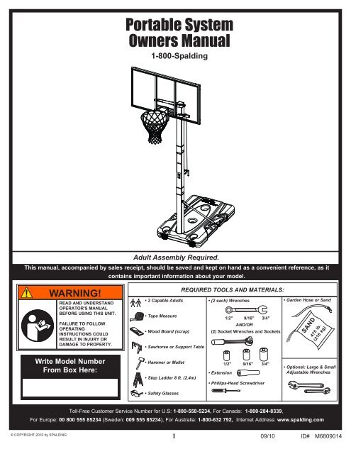
<strong>Portable</strong> <strong>System</strong><br />
Owners <strong>Manual</strong><br />
1-800-<strong>Spald<strong>in</strong>g</strong><br />
Adult Assembly Required.<br />
This manual, accompanied by sales receipt, should be saved and kept on hand as a convenient reference, as it<br />
conta<strong>in</strong>s important <strong>in</strong>formation about your model.<br />
WARNING!<br />
ReAd ANd uNdeRSTANd<br />
opeRAToR'S MANuAl<br />
BeFoRe uSING THIS uNIT.<br />
FAIluRe To FolloW<br />
opeRATING<br />
INSTRucTIoNS could<br />
ReSulT IN INjuRy oR<br />
dAMAGe To pRopeRTy.<br />
• 2 Capable Adults<br />
• Tape Measure<br />
• Wood Board (scrap)<br />
• Sawhorse or Support Table<br />
REQUIRED TOOLS AND MATERIALS:<br />
• (2 each) Wrenches<br />
1/2" 9/16" 3/4"<br />
AND/OR<br />
(2) Socket Wrenches and Sockets<br />
• Garden Hose or Sand<br />
SANd SANd<br />
475 475 lb. lb.<br />
(216 (216 kg) kg)<br />
Write Model Number<br />
From Box Here:<br />
• Hammer or Mallet<br />
• Step Ladder 8 ft. (2.4m)<br />
• Extension<br />
1/2" 9/16" 3/4"<br />
• Phillips-Head Screwdriver<br />
• Optional: Large & Small<br />
Adjustable Wrenches<br />
• Safety Glasses<br />
Toll-Free Customer Service Number for U.S: 1-800-558-5234, For Canada: 1-800-284-8339,<br />
For Europe: 00 800 555 85234 (Sweden: 009 555 85234), For Australia: 1-800-632 792, Internet Address: www.spald<strong>in</strong>g.com<br />
© COPYRIGHT 2010 by SPALDING<br />
1 09/10 ID# M6809014
BeFoRe you START<br />
To ensure optimal playability of backboard system, a close tolerance fit between the elevator components and<br />
hardware is required. Test-fit large bolts <strong>in</strong>to large holes of elevator tubes, backboard brackets, and triangle plates.<br />
Carefully rock them <strong>in</strong> a circular motion to ream out any excess pa<strong>in</strong>t from holes if necessary.<br />
NoTe: Not all items pictured are <strong>in</strong>cluded with every model.<br />
HEIGHT<br />
ADJUSTMENT<br />
Rotate crank<br />
handle to raise<br />
and lower<br />
backboard 33<br />
A<br />
B<br />
MOVING SYSTEM<br />
1. While hold<strong>in</strong>g pole, rotate basketball sytem<br />
forward until wheels engage with ground.<br />
2. Move basketball system to desired location.<br />
3. Carefully rotate basketball system upright.<br />
4. Check system for stability.<br />
1<br />
2<br />
3<br />
568090 06/06<br />
NOTICE TO ASSEMBLERS<br />
Adult Assembly Required. Dispose of ALL packag<strong>in</strong>g materials promptly. As with all products, periodically <strong>in</strong>spect<br />
for loose small parts.<br />
Assembled unit MUST be filled with sand or water at ALL times.<br />
ALL basketball systems, <strong>in</strong>clud<strong>in</strong>g those used for DISPLAYS, MUST be assembled and <strong>in</strong>stalled accord<strong>in</strong>g to<br />
<strong>in</strong>structions. Failure to follow <strong>in</strong>structions could result <strong>in</strong> SERIOUS INJURY. It is NOT acceptable to devise a<br />
makeshift support system.<br />
2
SAFeTy INSTRucTIoNS<br />
FAIluRe To FolloW THeSe SAFeTy INSTRucTIoNS MAy ReSulT IN SeRIouS INjuRy<br />
oR pRopeRTy dAMAGe ANd WIll VoId WARRANTy.<br />
Owner must ensure that all players know and follow these rules for safe operation of the<br />
system.<br />
To ensure safety, do not attempt to assemble this system without follow<strong>in</strong>g the <strong>in</strong>structions<br />
carefully. check entire box and <strong>in</strong>side all pack<strong>in</strong>g material for parts and/or additional<br />
<strong>in</strong>struction material. Before beg<strong>in</strong>n<strong>in</strong>g assembly, read the <strong>in</strong>structions and identify parts<br />
us<strong>in</strong>g the hardware identifier and parts list <strong>in</strong> this document. proper and complete<br />
assembly, use, and supervision are essential for proper operation and to reduce the risk of<br />
accident or <strong>in</strong>jury. A high probability of serious <strong>in</strong>jury exists if this system is not <strong>in</strong>stalled,<br />
ma<strong>in</strong>ta<strong>in</strong>ed, and operated properly.<br />
• If us<strong>in</strong>g a ladder dur<strong>in</strong>g assembly, use extreme caution.<br />
• check base regularly for leakage. Slow leaks could cause the system to tip over<br />
unexpectedly.<br />
• Seat the pole sections properly (if applicable). Failure to do so could allow the pole sections<br />
to separate dur<strong>in</strong>g play and/or dur<strong>in</strong>g transport of the system.<br />
• climate, corrosion or misuse could result <strong>in</strong> system failure.<br />
• If technical assistance is required, contact customer Service.<br />
• M<strong>in</strong>imum operational height is 6'-6" (1.98m) to the bottom of backboard.<br />
Most <strong>in</strong>juries are caused by misuse and/or not follow<strong>in</strong>g <strong>in</strong>structions. Use caution when us<strong>in</strong>g this unit.<br />
IMpoRTANT!<br />
Remove all contents from boxes.<br />
Be sure to check <strong>in</strong>side pole sections,<br />
hardware and additional parts are packed <strong>in</strong>side.<br />
WARNING!<br />
IF youR SySTeM IS eQuIpped WITH AN AcRylIc BAcKBoARd, eXAMINe BAcKBoARd FoR ANy<br />
dAMAGe THAT MAy HAVe occuRRed duRING SHIpMeNT. cRAcKS IN THe BAcKBoARd could<br />
ReSulT IN SuddeN BReAKAGe. IF BAcKBoARd IS dAMAGed IN ANy WAy pRIoR To oR AFTeR<br />
ASSeMBly, cAll Toll-FRee NuMBeR: u.S. 1-800-558-5234; cANAdA: 1-800-284-8339;<br />
http://www.spald<strong>in</strong>g.com<br />
3
Get to know the basic parts of your basketball system...<br />
FRoNT VIeW<br />
BAcK VIeW<br />
BACKBOARD<br />
RIM<br />
ELEVATOR ASSEMBLY<br />
TOP POLE<br />
MIDDLE POLE<br />
BASE<br />
BOTTOM POLE<br />
STRUTS<br />
WHEEL CARRIAGE ASSEMBLY<br />
4
PARTS LIST - See Hardware Identifier<br />
Item Qty. Part No. Description<br />
1 1 600262 Tank<br />
2 2 906410 Strut, Pole to Base<br />
3 1 80034402 Screw Jack Assembly<br />
4 1 FR908402 Top Pole Section<br />
5 1 FR908401 Middle Pole Section<br />
6 1 FR908403 Bottom Pole Section<br />
7 2 800332 Wheel Bracket<br />
8 2 600056 Wheel, 3.5”<br />
9 1 10830601 Rod, Axle<br />
10 2 203099 Nut, Ny-lock, 5/16-18<br />
11 1 600165 Cap, Cover, Height Indicator<br />
12 1 202662 Bolt, Hex Head, 5/16-18 x 4-1/2 Long<br />
13 2 207550 Pushnut, 7/16 Shaft Diameter<br />
14 8 203100 Hex Flange Nut 5/16-18<br />
15 1 908415 Bracket, Pole Mount<br />
16 2 204846 Carriage Bolt, 5/16-18 x 4.5 Long<br />
17 1 600164 Cover, Upper Tube<br />
18 6 203153 Bolt, Hex Head, 5/16-18 x .75 Long<br />
19 1 108181 Plate, Pole Mount<strong>in</strong>g<br />
20 1 201518 Bolt, Hex Head, 5/16-18 x 2.75 Long<br />
21 1 700009 Handle, Elevator Assembly<br />
22 1 202528 P<strong>in</strong>, Actuator Assembly<br />
23 4 205679 Bolt, Hex Head, 1/2-13 x 2 Long<br />
24 8* 203218 Washer, Flat, 5/16<br />
25 2 203679 Bolt, Hex Head, 3/8-16 x 2 Long<br />
26 4 203104 Bolt, Hex Head, 5/16-18 x 2 Long<br />
27 1 908416 Plate<br />
Item Qty. Part No. Description<br />
28 1 908355 Cover Plate, Rim<br />
29 3 205678 Bolt, Hex Head, 1/2-13 x 7 Long<br />
30 8 201651 Spacer, Plastic, .530 I.D. x .25 Long<br />
31 7 206340 Lock Nut, Hex 1/2-13<br />
32 2 908412 Elevator Tube, Lower - Long<br />
33 1 568090 Label, Height Adjustment and Mov<strong>in</strong>g<br />
FR568090 Label, Height Adjustment and Mov<strong>in</strong>g, French<br />
34 1 Rim<br />
35 2 908411 Elevator Tube, Upper - Short<br />
36 2 202587 Spacer, .530 I.D. x 1” Long<br />
37 1 203470 Washer, Flat, .625 I.D. x .1.5 O.D.<br />
38 1 600052 Cap, Pole Top<br />
39 2 204558 Screw, 1/4 x .375 Long<br />
40 2 205528 Bolt, Hex Flange, 5/16-18 x 1 Long<br />
41 1 203617 Cap, Base<br />
42 1 206989 Re<strong>in</strong>forcement Bracket<br />
43 1 Net<br />
44 1 900033 Bracket, Slam Jam<br />
45 1 206048 Bolt, Tee, 3/8-16, 3.25” Long<br />
46 1 200318 Bracket, Re<strong>in</strong>forcement, Slam Jam<br />
47 1 206049 Spr<strong>in</strong>g, Rim<br />
48 1 203795 Nut, Special, 3/8-16<br />
49 2 205842 Washer, Flat, .344 I.D. x .1.5 O.D.<br />
*You may have extra parts with this model.<br />
NoTe<br />
Hardware kit is designed for more than one<br />
style of basketball system. Not all hardware<br />
will be used.<br />
5
HARDWARE IDENTIFIER (BOLTS & SCREWS)<br />
#29 (3)<br />
#12 (1) #39 (2)<br />
#20 (1) #25 (2)<br />
#23 (4)<br />
#26 (4)<br />
#40 (2)<br />
BOL<br />
#16 (2)<br />
#18 (6)<br />
#45 (1)<br />
HARDWARE IDENTIFIER (NUTS & WASHERS)<br />
#10 (2)<br />
#14 (8)<br />
#31 (7) #48 (1)<br />
#37 (1)<br />
#49 (2)<br />
6<br />
#24 (8)*<br />
* You may have extra parts with this model.
HARDWARE IDENTIFIER (PLASTIC SPACERS CAPS & CLIPS)<br />
#13 (2)<br />
#30 (8)<br />
#36 (2)<br />
HARDWARE IDENTIFIER (OTHER)<br />
#47 (1)<br />
#46 (1)<br />
#44 (1)<br />
7<br />
07/09 ID# M6809013
SecTIoN A: ASSEMBLE THE BASE<br />
This is what your system will look like when<br />
you’ve f<strong>in</strong>ished this section.<br />
ToolS ReQuIRed FoR THIS SecTIoN<br />
(2) Wrenches<br />
1/2” 9/16”<br />
Hammer or Mallet<br />
ANd/oR<br />
(2) Socket Wrenches and Sockets<br />
1/2”<br />
9/16”<br />
extension<br />
Sawhorse or<br />
Support Table<br />
1.<br />
Complete wheel assembly as shown <strong>in</strong> Figure A. Secure wheel bracket (7) and wheel assembly (Fig. A.)<br />
to the tank (1) with a bolts (18) and washers (24). Repeat procedure for opposite wheel.<br />
Fig. A.<br />
NoTe:<br />
To INSTAll SecoNd<br />
puSHNuT:<br />
• Assemble pushnut,<br />
Wheels, Axle, And<br />
Wheel Bracket As<br />
Shown.<br />
1<br />
Wood Block<br />
• Support pushnut/Axle<br />
From The end With A<br />
Block of Wood To<br />
Install The Second<br />
pushnut onto The<br />
Axle.<br />
24<br />
18<br />
18<br />
24<br />
18<br />
24<br />
18<br />
24<br />
7<br />
7<br />
9 13<br />
13<br />
8<br />
8<br />
8
2.<br />
Correctly identify each pole section. Poles have an identification sticker that will be used as a<br />
reference po<strong>in</strong>t <strong>in</strong> the next step.<br />
MIddle<br />
5<br />
IdeNTIFIcATIoN STIcKeR<br />
IdeNTIFIcATIoN STIcKeR<br />
4 6<br />
BoTToM<br />
Top<br />
3.<br />
Bounce middle pole section (5) <strong>in</strong>to top section (4) us<strong>in</strong>g a wood scrap as shown until the top pole no<br />
longer moves toward the pole identification sticker on the middle pole.<br />
5<br />
cAuTIoN!<br />
THe IdeNTIFIcATIoN STIcKeR IS<br />
locATed 6" FRoM THe eNd oF<br />
THe pole. WHeN pRopeRly<br />
pouNded ToGeTHeR, THe pole<br />
SecTIoNS SHould HAVe A 4-1/2"<br />
MINIMuM oVeRlAp, leAVING 1-1/2"<br />
BeTWeeN THe oVeRlAppING pole<br />
ANd THe IdeNTIFIcATIoN STIcKeR.<br />
IMpoRTANT!<br />
NoTe oRIeNTATIoN<br />
oF poleS.<br />
4<br />
Wood Scrap (not supplied)<br />
9
4.<br />
Bounce top and middle pole assembly (4 and 5)<br />
onto bottom pole section (6) us<strong>in</strong>g a wood scrap<br />
as shown. Bounce until the top and middle pole<br />
assembly no longer moves toward the pole<br />
identification mark on the bottom pole.<br />
IMpoRTANT!<br />
NoTe oRIeNTATIoN.<br />
5. Attach pole assembly to tank (1) as shown.<br />
Secure pole assembly to tank us<strong>in</strong>g bolts (25)<br />
and pole mount<strong>in</strong>g plate (19) as shown.<br />
WARNING!<br />
TWo cApABle AdulTS<br />
ReQuIRed FoR THIS<br />
pRoceduRe. FAIluRe To<br />
FolloW THIS WARNING could<br />
ReSulT IN SeRIouS INjuRy<br />
ANd/oR pRopeRTy dAMAGe.<br />
4<br />
6<br />
5<br />
6<br />
Wood Scrap<br />
(not supplied)<br />
10<br />
25<br />
19
6. Secure tank struts (2) to pole as shown.<br />
WARNING!<br />
TWo cApABle AdulTS<br />
ReQuIRed FoR THIS<br />
pRoceduRe. FAIluRe To<br />
FolloW THIS WARNING could<br />
ReSulT IN SeRIouS INjuRy<br />
ANd/oR pRopeRTy dAMAGe.<br />
IMpoRTANT!<br />
do NoT TIGHTeN<br />
coMpleTely.<br />
10<br />
2<br />
2<br />
12<br />
11
7.<br />
Rotate non-secured ends of tank struts (2) outward to<br />
mount<strong>in</strong>g holes <strong>in</strong> tank as shown. Secure non-secured<br />
ends of tank struts (2) to tank as shown. Repeat for<br />
opposite side.<br />
2<br />
2<br />
WARNING!<br />
TWo cApABle AdulTS<br />
ReQuIRed FoR THIS<br />
pRoceduRe. FAIluRe To<br />
FolloW THIS WARNING could<br />
ReSulT IN SeRIouS INjuRy<br />
ANd/oR pRopeRTy dAMAGe.<br />
40<br />
24<br />
2<br />
2<br />
40<br />
24<br />
49<br />
14<br />
49<br />
14<br />
IMpoRTANT!<br />
do NoT TIGHTeN<br />
coMpleTely.<br />
IMpoRTANT!<br />
Struts MuST be attached to<br />
the base through the<br />
lARGeR holes.<br />
8.<br />
Install pole mount bracket (15) and<br />
re<strong>in</strong>forcement bracket (42) with carriage bolts<br />
(16) as shown. Tighten flange nuts (14)<br />
completely.<br />
6<br />
14<br />
IMpoRTANT!<br />
do NoT oVeR<br />
TIGHTeN!<br />
16<br />
42<br />
15<br />
IMpoRTANT!<br />
TIGHTeN All HARdWARe<br />
FRoM STepS 6-8 AFTeR THIS<br />
ASSeMBly IS coMpleTed.<br />
12
9.<br />
Securely rest the assembly on sawhorse.<br />
Identify elevator tubes (32 and 35).<br />
35<br />
WARNING!<br />
TWo cApABle AdulTS<br />
ReQuIRed FoR THIS<br />
pRoceduRe. FAIluRe To<br />
FolloW THIS WARNING could<br />
ReSulT IN SeRIouS INjuRy<br />
ANd/oR pRopeRTy dAMAGe.<br />
35<br />
32<br />
Toward pole<br />
upper elevator Tube 32<br />
Toward Board<br />
lower elevator Tube<br />
10.<br />
While the system is securely rest<strong>in</strong>g on the sawhorse. Install elevator tubes (32 and 35) to top pole<br />
section (4) as shown. Install pole cap (38) at this time.<br />
coMpleTed ASSeMBly<br />
29<br />
29<br />
38<br />
35<br />
4<br />
30<br />
30<br />
WARNING!<br />
30<br />
30<br />
32<br />
31<br />
35<br />
TIGHTeN BolT (29) IN<br />
locK NuT (31) uNTIl<br />
FluSH (eVeN) WITH locK<br />
NuT’S ouTeR edGe.<br />
31<br />
32<br />
13
SecTIoN B: ATTACH THE BACKBOARD<br />
This is what your system will look like when<br />
you’ve f<strong>in</strong>ished this section.<br />
ToolS ReQuIRed FoR THIS SecTIoN<br />
(2) Wrenches<br />
1/2” 9/16” 3/4”<br />
ANd/oR<br />
(2) Socket Wrenches and Sockets<br />
1/2” 9/16” 3/4”<br />
extension<br />
Sawhorse or Support Table<br />
phillips Screwdriver<br />
1.<br />
While still supported on sawhorse. Attach elevator tubes (32) to backboard us<strong>in</strong>g spacers (30), bolts (23),<br />
and nuts (31) as shown.<br />
23 23<br />
30<br />
30<br />
31<br />
31<br />
31<br />
31<br />
30<br />
30<br />
23<br />
23<br />
14
2.<br />
Insert T-bolt (45) <strong>in</strong>to Slam Jam bracket (44) then, attach that assembly to board us<strong>in</strong>g<br />
bolts (26) and nuts (14).<br />
carefully cut<br />
and peel<br />
protective film<br />
away from<br />
board prior to<br />
attach<strong>in</strong>g rim.<br />
IMpoRTANT!<br />
14<br />
27<br />
45<br />
44<br />
26<br />
15
3.<br />
Install Slam jam Rim to Backboard<br />
A. Fit rim (34) securely <strong>in</strong>to bracket (44) as shown. Allow T-bolt (45)<br />
to slip through center hole <strong>in</strong> rim (34).<br />
B. Install re<strong>in</strong>forcement bracket (46) onto T-bolt (45) as shown.<br />
c. Install spr<strong>in</strong>g (47) onto T-bolt (45) as shown.<br />
d. Install special nut (48) and washer (37) onto T-bolt (45).<br />
e. Tighten nut (48) until 1/8" of the bolt threads on end of T-bolt (45)<br />
are exposed.<br />
46<br />
NoTe:<br />
oRIeNTATIoN<br />
oF BRAcKeT<br />
A<br />
34<br />
B<br />
46<br />
45<br />
44<br />
45<br />
c<br />
d<br />
47<br />
45<br />
48<br />
37<br />
e<br />
45<br />
37<br />
48<br />
16
4. Place cover (17) onto screw-jack assembly (3). Install cap (11).<br />
A.<br />
17<br />
11<br />
3<br />
B.<br />
Install handle assembly (3, 17 and 11) to lower elevator tubes (32) us<strong>in</strong>g bolt (29), spacers (36),<br />
and nut (31) as shown.<br />
3<br />
36<br />
36<br />
4<br />
31<br />
29<br />
32<br />
32<br />
WARNING!<br />
IMpoRTANT!<br />
Note orientation of handle.<br />
TIGHTeN BolT (29) IN<br />
locK NuT (31) uNTIl<br />
FluSH (eVeN) WITH locK<br />
NuT’S ouTeR edGe.<br />
17
5.<br />
Secure the handle assembly (3, 17 and 11) to pole bracket (15) us<strong>in</strong>g bolt (20) and nut (10) as shown.<br />
NoTe:<br />
Before go<strong>in</strong>g on to next<br />
step, set adjustable<br />
system assembly to<br />
the 10’ (3.05 m)<br />
sett<strong>in</strong>g.<br />
3<br />
20<br />
10<br />
15<br />
WARNING!<br />
TIGHTeN BolT (20) IN<br />
locK NuT (10) uNTIl<br />
FluSH (eVeN) WITH locK<br />
NuT’S ouTeR edGe.<br />
18
6.<br />
Roll completed assembly to desired position. Fill tank with water (approx. 40 gallons (128 Liters)) or<br />
sand (approx. 475 lbs. (216 kg)) and rotate the cap (41) <strong>in</strong>to base (1).<br />
WARNING!<br />
Cap (41) MUST be tightened COMPLETELY and<br />
SECURELY to prevent leakage.<br />
cHecK WATeR leVel BeFoRe eAcH uSe!<br />
FAIluRe To FolloW THIS WARNING could<br />
ReSulT IN SeRIouS INjuRy ANd/oR<br />
pRopeRTy dAMAGe.<br />
41<br />
1<br />
WARNING!<br />
TWo cApABle AdulTS<br />
ReQuIRed FoR THIS<br />
pRoceduRe. FAIluRe To<br />
FolloW THIS WARNING<br />
could ReSulT IN SeRIouS<br />
INjuRy ANd/oR pRopeRTy<br />
dAMAGe.<br />
do NoT leAVe ASSeMBly<br />
uNATTeNded WHeN eMpTy;<br />
IT MAy TIp oVeR.<br />
cAuTIoN!<br />
Add TWo GAlloNS (7.6<br />
lITeRS) oF NoN-ToXIc<br />
ANTIFReeZe IN SuB-<br />
FReeZING clIMATeS.<br />
SANd SANd<br />
(475 (475 lb.) lb.)<br />
(216 (216 kg) kg)<br />
IF USING SAND: 2 GAlloNS<br />
oF ANTI-FReeZe IS NoT<br />
ReQuIRed.<br />
19
7.<br />
Install net (43).<br />
A.<br />
ouTSIde VIeW<br />
B. c.<br />
d.<br />
34<br />
43<br />
43<br />
34<br />
8.<br />
Apply Height Adjustment and Mov<strong>in</strong>g Label (33) to<br />
front of pole, where it is clearly visible.<br />
cAuTIoN!<br />
HEIGHT<br />
ADJUSTMENT<br />
Rotate crank<br />
handle to raise<br />
and lower<br />
backboard.<br />
Do not over crank<br />
handle beyond the<br />
manufactured height<br />
<strong>in</strong>dicator range of<br />
7-1/2 - 10 feet.<br />
Damage may be<br />
caused to the screw<br />
jack’s <strong>in</strong>ternal<br />
adjustment<br />
mechanism if<br />
adjusted over 10 or<br />
under 7-1/2 feet.<br />
33<br />
MOVING SYSTEM<br />
1. While hold<strong>in</strong>g pole, rotate basketball sytem<br />
forward until wheels engage with ground.<br />
2. Move basketball system to desired location.<br />
B<br />
A<br />
Check system for stability.<br />
B<br />
A<br />
do NoT oVeR-cRANK HANdle<br />
BeyoNd THe MANuFAcTuRed<br />
HeIGHT-INdIcAToR RANGe oF<br />
7-1/2 - 10 FeeT. dAMAGe MAy<br />
Be cAuSed To THe ScReW<br />
jAcK’S INTeRNAl<br />
AdjuSTMeNT MecHANISM IF<br />
AdjuSTed oVeR 10 oR<br />
uNdeR 7-1/2 FeeT.<br />
HeIGHT ANd MoVING lABel<br />
MuST NoT oBSTRucT<br />
FAcToRy ATTAcHed WARNING<br />
lABel.<br />
3. Carefully rotate basketball system upright.<br />
4. Check system for stability.<br />
NoTe:<br />
2<br />
3<br />
1<br />
568090 11/06<br />
21<br />
22<br />
Handle (21) can be<br />
removed and<br />
stored by remov<strong>in</strong>g<br />
p<strong>in</strong> (22).<br />
RIM COVER ATTACHMENT<br />
9.<br />
NoTe:<br />
34<br />
39<br />
Cover plate (28) will fit<br />
INSIDE back bracket.<br />
39<br />
28<br />
20