Shaved 40 - uri=spal-usa
Shaved 40 - uri=spal-usa
Shaved 40 - uri=spal-usa

You also want an ePaper? Increase the reach of your titles
YUMPU automatically turns print PDFs into web optimized ePapers that Google loves.
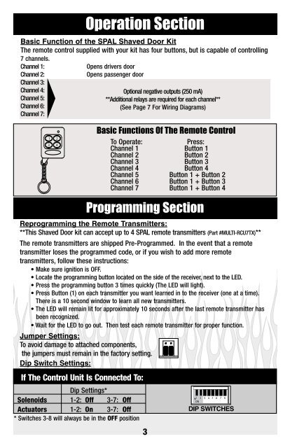
Basic Function of the SPAL <strong>Shaved</strong> Door Kit<br />
The remote control supplied with your kit has four buttons, but is capable of controlling<br />
7 channels.<br />
Channel 1:<br />
Opens drivers door<br />
Channel 2:<br />
Channel 3:<br />
Channel 4:<br />
Channel 5:<br />
Channel 6:<br />
Channel 7:<br />
Operation Section<br />
Opens passenger door<br />
Optional negative outputs (250 mA)<br />
**Additional relays are required for each channel**<br />
(See Page 7 For Wiring Diagrams)<br />
Negative Trigger<br />
Negative Trigger<br />
1 2<br />
3 4<br />
Basic Functions Of The Remote Control<br />
To Operate:<br />
1 2 3 Press: 4 5 6 7 8<br />
Channel 1 ON Button 1<br />
Channel 2 Button 2<br />
Channel 3 Button 3<br />
Channel 4 Button 4<br />
Channel 5 Button 1 + Button 2<br />
Channel 6 Button 1 + Button 3<br />
Channel 7 Button 1 + Button 4<br />
TTERY<br />
ABLE CRIMPS<br />
Brown or Yellow<br />
Wire of Receiver<br />
Programming Section<br />
CIRCUIT<br />
COLOR<br />
GROUND<br />
BLACK<br />
CHANNEL 2 INPUT<br />
GREEN<br />
CHANNEL 7<br />
PURPLE<br />
Reprogramming 35 Amp Fuse the Remote Transmitters:<br />
CHANNEL 5<br />
BLUE<br />
CHANNEL 3<br />
ORANGE<br />
EMERGENCY<br />
+12V<br />
RED<br />
**This <strong>Shaved</strong> Door kit can accept up to 4 IGNITION SPAL remote YELLOW transmitters (Part #MULTI-RCU7TX)**<br />
CHANNEL 1 INPUT<br />
GREY<br />
SWITCH<br />
CHANNEL 6<br />
WHITE/BLACK<br />
CHANNEL 4<br />
BROWN<br />
The remote transmitters are shipped Pre-Programmed. In the event that a remote<br />
transmitter loses the programmed code, or if you wish to add more remote<br />
transmitters, follow these instructions:<br />
• Make sure ignition is OFF.<br />
To Brown or Yellow<br />
Wire from Spade Connector<br />
Harness of Receiver<br />
• Locate the programming button located on the side of the receiver, next to the LED.<br />
• Press the programming button 3 times quickly (The LED will light).<br />
• Press Button (1) on each transmitter you want learned in to the receiver (one at a time).<br />
There is a 10 second window to learn all new transmitters.<br />
• The LED will remain lit for approximately 10 seconds after the last remote transmitter has<br />
been recognized.<br />
Negative Trigger<br />
• Wait for the LED to go out. Then test each remote transmitter for proper function.<br />
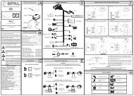
Jumper Settings:<br />
To avoid damage to attached components,<br />
1 2<br />
3 4<br />
the jumpers must remain in the factory setting.<br />
Dip Switch Settings:<br />
DOOR LATCH<br />
MECHANISM ARM<br />
If The Control Unit Is Connected To:<br />
DOOR LATCH<br />
MECHANISM ARM<br />
Dip Settings*<br />
1 2<br />
Solenoids<br />
CABLE CRIMPS<br />
1-2: Off<br />
3 4<br />
3-7: Off<br />
Actuators 1-2: On 3-7: 35 Amp Fuse Off<br />
* Switches 3-8 will always be in the OFF position<br />
EMERGENCY<br />
SWITCH<br />
3<br />
Negative Trigger<br />
Negative Trigger<br />
Negative Trigger<br />
To Brown or Yellow<br />
1 2 3 4 5 6 7 8<br />
ON<br />
1 2 3 4 5 6 7 8<br />
ON<br />
DIP SWITCHES