Aquaflex AQWE6 - Swift Owners Club
Aquaflex AQWE6 - Swift Owners Club
Aquaflex AQWE6 - Swift Owners Club

You also want an ePaper? Increase the reach of your titles
YUMPU automatically turns print PDFs into web optimized ePapers that Google loves.
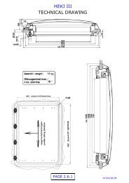
Fitted Equipment<br />
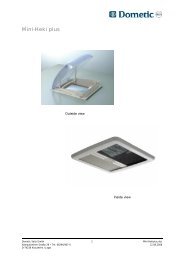
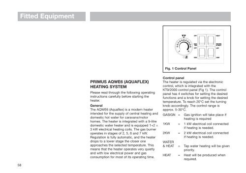
Fig. 1 Control Panel<br />
58<br />
PRIMUS <strong>AQWE6</strong> (AQUAFLEX)<br />
HEATING SYSTEM<br />
Please read through the following operating<br />
instructions carefully before starting the<br />
heater.<br />
General<br />
The <strong>AQWE6</strong> (<strong>Aquaflex</strong>) is a modern heater<br />
intended for the supply of central heating and<br />
domestic hot water for caravans/motor<br />
homes. The heater is integrated with a 9-litre<br />
domestic water heater and is equipped 1+2 =<br />
3 kW electrical heating coils. The gas burner<br />
operates in stages of 2, 5, 6 and 7 kW.<br />
Regulation is fully automatic, and the heater<br />
drops to a lower stage the closer one<br />
approaches the selected temperature. This<br />
means that the heater operates very quietly<br />
and with low electrical power and gas<br />
consumption for most of its operating time.<br />
Control panel<br />
The heater is regulated via the electronic<br />
control, which is integrated with the<br />
KT9/2000 control panel (Fig 1). The control<br />
panel has 4 switches for setting the desired<br />
functions and a knob for setting the desired<br />
temperature. To reach 20°C set the turning<br />
knob accordingly. The control range is<br />
approx. 5-30°C.<br />
GASIGN = Gas ignition will take place if<br />
heating is required<br />
1KW = 1 kW electrical coil connected<br />
if heating is needed.<br />
2KW = 2 kW electrical coil connected<br />
if heating is needed.<br />
WATER<br />
& HEAT = Tap water heating will be given<br />
priority.<br />
HEAT = Heat will be produced when<br />
required.
GASIGN means that the gas heater will start<br />
if heating is required. This switch should be<br />
in the On position at all times, except if the<br />
gas heater is not required to operate for<br />
whatever reason.<br />
1KW and 2KW means that the electrical<br />
heating coils will be switched on as heating<br />
is required. Both 1 and 2 kW electrical<br />
heating has to be selected when 3 kW is<br />
required.<br />
Note. The choice of electrical power is<br />
ultimately governed by the current available<br />
from the site supply. A 5A outlet can allow<br />
1000W, a 10A allows 2000W and a 16A<br />
allows 3000W.<br />
WATER & HEAT means that heating tap<br />
water takes priority over room heating: When<br />
larger amounts of hot water is required for<br />
showering, washing or such then this button<br />
should be in the ON position. During cold<br />
periods enough hot water is normally<br />
produced at the same time as the living area<br />
is heated so it can be set in the HEAT<br />
position and it should always be in the HEAT<br />
position when no water is fed into the water<br />
heater. Heat will still be produced if the<br />
thermostat is not turned down.<br />
HEAT. Hot water will be produced, as<br />
described above, as a function of the<br />
requirement to heat the living area except<br />
when the outside temperature is high and no<br />
heating of the living area will be required.<br />
Then the setting should be WATER & HEAT<br />
and the thermostat turned down.<br />
Both gas and electric can be connected at<br />
the same time if so desired.<br />
NB. The programmable timer unit must be in<br />
the ON position to operate the heating<br />
system. (see Programmable Timer<br />
Instructions)<br />
Mode of operation of the heater<br />
Control of the heater takes place fully<br />
automatically once the basic setting<br />
described above has been made. If both<br />
electrical and gas heating is selected priority<br />
is given to electrical heating.<br />
If the setting has been made for automatic<br />
water heating, WATER & HEAT, priority will<br />
always be given to hot water. Except in the<br />
case of a living area which has fully cooled<br />
down, when the heater will prioritise room<br />
heating until the heat in the room has<br />
reached an acceptable level. The heater will<br />
then check the room temperature and water<br />
temperature alternately and will generate<br />
room heating or hot water as required. This<br />
means that hot water is always available,<br />
and that room heating is provided as<br />
required. It takes about 15-20 minutes to<br />
produce hot water starting from a fully cold<br />
system.<br />
The temperature of the hot water is limited to<br />
70°C. Note that 70°C is a high hot-water<br />
temperature and precautions should be<br />
taken during use.<br />
Fitted Equipment<br />
If the red lamp lights up, this indicates that<br />
the heater has gone into safety mode as a<br />
consequence of the gas heater having<br />
attempted to ignite and having failed to ignite<br />
or that the built in secondary overheat<br />
thermostat has acted. This is usually because<br />
the gas supply has run out, but it may also<br />
be caused by the presence of air in the gas<br />
line or by a blocked gas supply or that the<br />
heater has been running without fluid.<br />
Turning the GASIGN Off and On should<br />
normally restart a tripped gas heater. Note<br />
that for the secondary overheat thermostat<br />
the heater has to cool down.<br />
Starting the heating system<br />
1. Make sure that the system has a power<br />
supply (12 V/220 V)<br />
2. Open the gas cylinder<br />
3. Check that the heating system is filled<br />
with water/glycol (60/40)<br />
4. Set the desired temperature.<br />
5. Turn on the desired function on the<br />
switches.<br />
6. If optional Timer is installed check that it<br />
is turned to On. (See Timer instructions)<br />
Shutting down the heating system<br />
1. Turn GASIGN and 1KW and 2KW<br />
switches Off. (If Timer is installed you<br />
only need to turn it Off )<br />
2. Close the gas cylinder<br />
59
Fitted Equipment<br />
3. Empty the water heater if there is a risk<br />
of frost<br />
4. Switch off the supply voltage<br />
Filling the water heater - domestic water<br />
1. Ensure that the drain valve of the heater<br />
is closed<br />
2. Start the fresh water pump<br />
3. Open a water tap and leave it open until<br />
water arrives. If a mixing valve is present<br />
set it to the hot position and allow filling<br />
to take place as described above.<br />
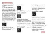
Emptying the domestic hot water heater<br />
1. Switch off the fresh water pump. When at<br />
risk from frost and heating is turned off,<br />
always drain the domestic hot water from<br />
the boiler<br />
Fig. 2<br />
60<br />
2. Open the drain valve on the heater by<br />
rotating the red knob by two clicks in an<br />
anti-clockwise direction (Fig.2)<br />
3. Open all the hot water taps.<br />
4. Check that water is running in the<br />
drainage pipe, (The easiest way is to look<br />
under the vehicle). This is particularly<br />
important during the winter, when snow<br />
and slush may block the pipe.<br />
Maintenance of domestic Hot water<br />
heater<br />
The heater may be descaled with vinegar or<br />
formic acid, or alternatively with a special<br />
descaling agent.<br />
The agent is added to the fresh water that is<br />
circulating through the system. After<br />
descaling, the system is flushed with clean<br />
water. (Do not use agents containing<br />
bleach). The domestic hot water heater can<br />
be removed from the main heater without<br />
affecting other functions. Depending on the<br />
position of installation the heater may require<br />
removal to provide access to the domestic<br />
hot water heater tank.<br />
Note. The exhaust outlet in such a case<br />
must be removed and refitted. The small O-<br />
ring in the exhaust-connecting piece must<br />
be replaced whenever the exhaust outlet is<br />
removed.<br />
The domestic hot water heater can be<br />
washed out and refitted. Check that the<br />
O-ring is undamaged before fitting.<br />
Note: Only nuts with metal friction locking<br />
may be used. Check that the domestic hot<br />
water heater is leak-proof after fitting by<br />
pressurising the system.<br />
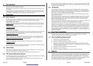
Electrical coils<br />
The heater is equipped with 2 electrical coils,<br />
with an output of 1000 + 2000W. Regulation<br />
is taken care of automatically by setting the<br />
switches as described earlier. The electrical<br />
coils have a mechanical overheating<br />
protection device capable of tripping if the<br />
system is operated without water.<br />
Pressing the red button on the side of the<br />
heater (Fig.3) performs resetting of the<br />
tripped overheating protection. Resetting is<br />
only possible after the system has cooled<br />
down, and the button must be pressed<br />
Fig. 3
firmly. If the protection trips once more, the<br />
cause of the fault must be investigated.<br />
Consult a specialist.<br />
The heater must only to be connected to<br />
the mains via the integrated 3 way<br />
connector provided.<br />
If the cover to the electrical heater is<br />
removed the mains must be disconnected.<br />
Important Note: Any interference with and<br />
modification to the heater may lead to<br />
serious functional problems. Changes to the<br />
gas or exhaust components can pose a<br />
direct risk to life, and Primus declines all<br />
responsibility in the event of such changes<br />
being made.<br />
1. The guarantee lapses with immediate<br />
effect if any work is performed other than<br />
by a specialist.<br />
2. Use only Primus original spare parts.<br />
3. Only a specialist must carry out repairs.<br />
4. The small O-ring must be replaced if the<br />
exhaust outlet is dismantled.<br />
5. The gas installation and any tests must<br />
conform to national requirements.<br />
6. Keep the exhaust outlet and the air inlet<br />
free from dirt, snow and ice.<br />
7. The heater must not be in use when<br />
refuelling and when in the garage.<br />
8. The domestic hot water heater is<br />
equipped with a safety valve, which<br />
Fitted Equipment<br />
opens at approx. 3 bar. (Any drainage<br />
takes place via a drainpipe through the<br />
floor.)<br />
9. The heater must be run with water/glycol<br />
(60/40) in the system at all times. If the<br />
heater is operated dry, it will normally be<br />
stopped by the operating thermostat. The<br />
thermostat will close after cooling, and<br />
the heater will then function normally<br />
provided that water is present in the<br />
system. If the operating thermostat fails<br />
to trip for any reason in the event of the<br />
system overheating, the heater will be<br />
stopped by a built-in secondary overheat<br />
thermostat. A red LED on the control<br />
panel indicates this. The electrical<br />
cartridge has a separate overheating<br />
protection.<br />
Technical Data<br />
<strong>AQWE6</strong><br />
Gas<br />
I3BP /I3+<br />
Working gas pressure<br />
30 mbar/28-30/37mbar I<br />
Wall exhaust<br />
Yes<br />
Volume Boiler<br />
9 lit<br />
Heating-up time hot water<br />
20 minutes<br />
Max D: H: W. pressure<br />
2,8 bar<br />
Length x Width x Height 500 x 400 x 300<br />
Weight (without water)<br />
15,1 kg<br />
Number of steps in gas burner 3<br />
Max power<br />
2.6/5.0/7.0 kW<br />
Technical Data<br />
<strong>AQWE6</strong><br />
Max gas consumption<br />
210/420/580 g/h<br />
Number of steeps electric heater 3<br />
Output electrical power<br />
1/2/3 kW<br />
Working voltage<br />
12 V = /230 V AC<br />
Electric power consumption 12 V 300/400/750 mA<br />
Electric power consumption 230 V 5/10/16 A<br />
Exhaust length max.<br />
45-mm<br />
Exhaust diameter<br />
54,3-mm<br />
Air inlet diameter<br />
88,3-mm<br />
61
Fitted Equipment<br />
62<br />
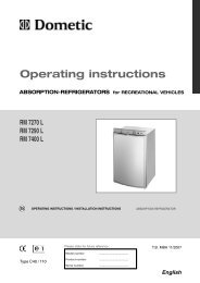
Fig. 1<br />
Note: Primus system with servicepump<br />
721850.<br />
There are two pumps installed in the heating<br />
system: One strong pump for filling and<br />
flushing the system and one weaker for<br />
normal use of the system. (For position of<br />
reservoir tank for filling see schematic<br />
heating layouts).<br />
The strong pump must be used during filling<br />
or topping up of the system and for flushing<br />
of air in the system.<br />
The manually operated switch for the service<br />
pump is situated alongside the 230V switch<br />
on the bed front.<br />
PROGRAMMABLE HEATING<br />
TIMER (USER INSTRUCTIONS)<br />
(Fig.1)<br />
Features: -<br />
• 7 Day / 24 Hour Programmable Timing<br />
• 12V DC Operation<br />
• Manual and Timed Override Option<br />
USER INSTRUCTIONS<br />
Setting the Clock: -<br />
1. Move the Function Select Slider Switch<br />
into the top "Clock set / Clock Adjust"<br />
position indicated by a Clock Face<br />
symbol.<br />
2. Set the day by pressing the<br />
corresponding day button M = Monday,<br />
T = Tuesday, etc.<br />
3. Set the time by using the + and - arrow<br />
keys to increase or decrease the time<br />
shown until the correct time is reached<br />
(Holding the + and - keys in will Scroll<br />
quickly to the desired time)<br />
Programming the Heating Timer: -<br />
1. Move the Red slider switch to the<br />
Position Marked "PROG" (Program).<br />
2. Using the + and - Arrow Keys set the first<br />
Program time, the ON time (note - ON is<br />
shown in the top right corner of the<br />
display)<br />
3. Set the Day or Days this switching time<br />
should be active, using the Day Select<br />
buttons.<br />
(Note - an active day will appear as mark<br />
at the bottom of the display
corresponding to a day select button.)<br />
4. Press the Enter Key to store this<br />
information. After pressing the Enter key<br />
the display will change, ready to set the<br />
next time. OFF or ON will be shown in the<br />
top right corner indicating which time is<br />
next.<br />
5. The next switching time can now be<br />
programmed by repeating steps 2, 3<br />
and 4.<br />
6. Run the programmed switching sequence<br />
by moving the Function Select Slider to<br />
the "Auto" position. The module will now<br />
carry out the switching operations as<br />
programmed, displaying the current time<br />
along with the state of the switch i.e. ON<br />
or OFF.<br />
Note - the Time display will not be seen if<br />
12V DC is not present.<br />
Timed / Manual Override.<br />
This function gives the ability to Manually<br />
override the Timer switch Program turning the<br />
Heating system ON or OFF, and also allows<br />
the user to set this override to last for a timed<br />
period (set in hours)<br />
Manual Override: -<br />
1. Move the Function select slider down to<br />
the "Timed / Manual Override" position.<br />
The display will read - h with ON or OFF<br />
to the Right (depending on the current<br />
switch state).<br />
2. Change the current switch state press the<br />
"On / Off Switch Select" button<br />
the<br />
display will<br />
change to read the new<br />
switch state on the right side. This timer<br />
will remain in this state until the Switch<br />
Select Button is pressed again or the<br />
Function select slider is returned to the<br />
"Auto" position and a switching program<br />
is run.<br />
Timed Override: -<br />
1 Move the Function Select Slider down to<br />
the "Timed Manual Override" position.<br />
The display will read - h with ON or OFF<br />
to the Right (depending on the current<br />
switch state).<br />
2. Set the override duration using the + and<br />
- "Up / Down Keys" the time is shown in<br />
(h) hours and (d) days and the set time<br />
can be from 1 to 23 hours or 1 to 27<br />
days.<br />
3. Change the current switch state to the<br />
override state by pressing the "On /Off<br />
Switch Select" button.<br />
4. Return the Function select slider to the<br />
"Auto" position. The override will start<br />
ONLY when the Function Select Slider is<br />
returned to the "Auto" mode, when in<br />
auto mode the ON / OFF display will flash<br />
to show the override state.<br />
Fitted Equipment<br />
Note on Duration: - If X hours are selected,<br />
the override timer decrementation will start<br />
on changing mode.<br />
If X days are selected, the override timer<br />
decrementation will start at midnight (the<br />
present day counting for a whole day).<br />
Power Supply<br />
The Programmable Timer Module requires a<br />
12v supply to operate fully, without this<br />
supply switching actions will not take place<br />
and the display in "Auto" Mode will not<br />
appear. The unit is fitted with internal battery<br />
backup of 25000hrs minimum reserve this<br />
will retain all programming and allow new<br />
programming when a 12v supply is not<br />
present.<br />
63
Fitted Equipment<br />
PRIMUS HEATING SYSTEM - BESSACARR CAMEO 535SL<br />
64
Fitted Equipment<br />
PRIMUS HEATING SYSTEM - BESSACARR CAMEO 550GL<br />
65
Fitted Equipment<br />
PRIMUS HEATING SYSTEM - BESSACARR CAMEO 625GL<br />
66