Boring tools with ISO elements - MAPAL Dr. Kress KG
Boring tools with ISO elements - MAPAL Dr. Kress KG
Boring tools with ISO elements - MAPAL Dr. Kress KG

Create successful ePaper yourself
Turn your PDF publications into a flip-book with our unique Google optimized e-Paper software.
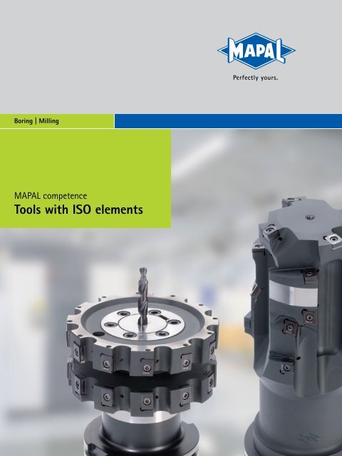
<strong>Boring</strong> | Milling<br />
<strong>MAPAL</strong> competence<br />
Tools <strong>with</strong> <strong>ISO</strong> <strong>elements</strong>
Perfect machining technology<br />
<strong>MAPAL</strong> stands for innovative machining solutions <strong>with</strong> the<br />
highest quality, precision and cost-effectiveness.<br />
Starting from fine bore machining, we offer our customers a<br />
comprehensive range of precision <strong>tools</strong> for machining cubic<br />
parts. In conjunction <strong>with</strong> tailored services we can design<br />
complete machining processes so that reliable, cost-effective<br />
manufacturing is guaranteed.<br />
<strong>ISO</strong> <strong>tools</strong> from <strong>MAPAL</strong> have achieved a leading role in the areas<br />
of boring, precision boring and milling. Building on<br />
its knowledge of fine machining, in recent<br />
years <strong>MAPAL</strong> has produced a wide range of<br />
cost-effective standard <strong>tools</strong> and a broad<br />
technological basis for customer-specific<br />
solutions.<br />
Our specialists tap major productivity<br />
potential for every machining task by<br />
means of a wide variety of design options<br />
and their deep process understanding.<br />
<strong>Dr</strong>. Jochen <strong>Kress</strong>
Reliable service – Worldwide<br />
Complete support from planning to<br />
the process<br />
c Planning and organising the<br />
complete machining process<br />
c Technical support during<br />
commissioning<br />
c Reliable and cost-effective tool<br />
supply by means of tool<br />
management<br />
c Worldwide availability<br />
The sound experience of <strong>MAPAL</strong><br />
specialists is available to customers<br />
worldwide during the entire<br />
collaboration process up to and<br />
including process support. Depending<br />
on the customers needs, individual<br />
custom <strong>tools</strong> are designed or the<br />
complete planning and process<br />
support taken over. However, support<br />
from <strong>MAPAL</strong> does not end <strong>with</strong> the<br />
start of production. Even during<br />
the production phase specialists<br />
from <strong>MAPAL</strong> assist the customer,<br />
optimise parameters or tool details,<br />
provide advice related to the process<br />
<strong>with</strong> their know-how and produce<br />
significant added value for the<br />
customer. With its complete range of<br />
services including tool management,<br />
<strong>MAPAL</strong> helps to keep production<br />
top notch: highly productive, costeffective<br />
and reliable.<br />
<strong>ISO</strong> <strong>tools</strong> and services from <strong>MAPAL</strong><br />
are available worldwide. With<br />
production facilities, sales and<br />
service offices in all relevant markets<br />
of the world, short channels for<br />
delivery and support are guaranteed.<br />
The systematic know-how transfer<br />
between the subsidiaries ensures<br />
consistent quality collaboration at<br />
the highest technical level.<br />
• Subsidiaries<br />
◦ Representatives
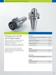
Competent in the standard<br />
Broad standard programme of <strong>tools</strong><br />
and indexable inserts<br />
c <strong>Boring</strong> large diameters <strong>with</strong> short<br />
machining times<br />
c High-performance milling cutters<br />
for a large number of machining<br />
tasks<br />
c Precise, cost-effective indexable<br />
inserts<br />
The usage of high performance,<br />
cost-effective standard <strong>tools</strong> plays a<br />
significant role in process design. In<br />
this area <strong>MAPAL</strong> has produced and<br />
brought to market maturity a broad<br />
range of <strong>tools</strong> and indexable inserts<br />
in recent years.<br />
For boring large diameters <strong>with</strong><br />
short machining times the tangential<br />
<strong>tools</strong> TSW and TFB have been further<br />
developed as a uniform and highly<br />
productive program for roughing and<br />
fine machining. In the milling area<br />
a high performance range of <strong>tools</strong><br />
is available as standard for a large<br />
number of machining tasks. And<br />
finally there is a completely new, costeffective<br />
range of indexable inserts for<br />
<strong>ISO</strong> <strong>tools</strong> available from stock.
Leading process solutions<br />
Optimised processes <strong>with</strong> matched<br />
complete machining <strong>tools</strong><br />
Reduced machining costs through<br />
<strong>ISO</strong> complete machining <strong>tools</strong> and<br />
hybrid <strong>tools</strong><br />
Intelligent engineering guarantees<br />
process reliability and<br />
straightforward handling<br />
The latest manufacturing facilities<br />
for precision <strong>tools</strong> at the highest<br />
level<br />
During the planning of new<br />
machining processes as well as the<br />
optimisation of existing processes,<br />
the focus is on the assessment of<br />
the machining time and the Cost Per<br />
Part (CPP). By means of intelligent,<br />
multi-stage, multi-cutting edge<br />
<strong>ISO</strong> combination <strong>tools</strong> or complete<br />
machining <strong>tools</strong>, both the productive<br />
times and the non-productive times<br />
can be significantly reduced. Here the<br />
design of intelligent tool solutions is<br />
not limited to just the <strong>ISO</strong> area. To<br />
prepare a solution that is optimal for<br />
the customer, different machining<br />
systems are combined into socalled<br />
hybrid <strong>tools</strong>. <strong>ISO</strong> <strong>tools</strong> from<br />
<strong>MAPAL</strong> meet both the requirement<br />
for process reliability and the<br />
requirement for straightforward<br />
handling – <strong>with</strong> intelligent and<br />
precise adapter solutions along<br />
<strong>with</strong> reliable, quick indexable insert<br />
mounting. The reliable principle<br />
of operation of <strong>MAPAL</strong> <strong>ISO</strong> <strong>tools</strong><br />
is ensured by the latest design<br />
methods that make it possible to<br />
assess collisions or to determine tool<br />
restrictions even during the planning<br />
phase. Production in the latest<br />
manufacturing facilities guarantees<br />
maximum tool precision.
Demanding machining tasks require<br />
maximum productivity<br />
Components such as engine blocks, brakes, turbochargers or swivel bearings, and also<br />
many other cubic parts from the automotive and commercial vehicle industry, mechanical<br />
engineering and systems engineering or the energy and aerospace industry require<br />
accuracies in the machining process in the range from IT 9 to IT 7. It must be possible to<br />
optimally machine mostly cored parts <strong>with</strong> high stock removal, large bore diameters and<br />
varying structures while taking into account the tolerance parameters, the stability of the<br />
part and the performance of the machine.<br />
<strong>ISO</strong> tool solutions are predestined for these requirements and cover the complete range<br />
of workpiece materials, in particular cast parts. Due to the large selection of cutting<br />
geometries, insert shapes and cutting materials, they are versatile in use and offer<br />
significant rationalisation potential during boring or milling in pre-machining or fine<br />
machining. The replaceable indexable inserts make the reconditioning of <strong>tools</strong> particularly<br />
straightforward and reduce the tool costs and as a consequence the Cost Per Part (CPP).<br />
Requirements on<br />
innovative tool solutions<br />
For all materials<br />
For numerous<br />
applications<br />
Increase productivity and quality<br />
Reduce productive and<br />
non-productive times<br />
Reduce costs<br />
Easy handling<br />
Universal use<br />
Conservation of resources<br />
P M K N S<br />
The numerous possibilities continue<br />
<strong>with</strong> the list of workpiece materials.<br />
The applications range from machining<br />
castings and steel, through the<br />
machining of demanding, high-alloy<br />
materials such as titanium or Inconel, to<br />
aluminium.<br />
Engine blocks<br />
6
Tools <strong>with</strong> <strong>ISO</strong> <strong>elements</strong> | Introduction<br />
Suspension<br />
Brakes Turbochargers Connecting rods<br />
Compressors<br />
Large engines<br />
Gearbox housing:<br />
mechanical engineering /<br />
system engineering<br />
Wind power<br />
7
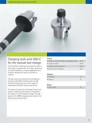
<strong>ISO</strong> <strong>tools</strong> from <strong>MAPAL</strong> –<br />
the leading technology<br />
The high customer requirements are met by <strong>MAPAL</strong> from the design to the manufacture<br />
of the <strong>tools</strong> by means of extensive know-how and the latest technology. For this reason<br />
<strong>ISO</strong> <strong>tools</strong> from <strong>MAPAL</strong> are leading in the custom sector and standard sector.<br />
The combination of continuous product innovations and a wealth of experience from<br />
more than 15 years gives the <strong>tools</strong> their high performance – <strong>with</strong> the objective of<br />
achieving higher part qualities, better tool lives and increased productivity.<br />
<br />
Precision, performance and innovative technology<br />
<br />
Process solutions –<br />
Perfectly yours<br />
<br />
<strong>MAPAL</strong> precision in design<br />
and production<br />
Advantages of<br />
<strong>MAPAL</strong> <strong>ISO</strong> <strong>tools</strong><br />
Reduction of the<br />
manufacturing costs per unit<br />
due to short machining times<br />
Combination <strong>tools</strong> for the<br />
reduction of the number of<br />
<strong>tools</strong> required<br />
High process reliability<br />
Maximum cost-effectiveness<br />
due to tangential technology<br />
Technology available<br />
worldwide<br />
To reduce productive and non-productive<br />
times simultaneously, <strong>MAPAL</strong> offers<br />
particularly high performance complete<br />
machining <strong>tools</strong>. Reduced cycle times, lower<br />
energy consumption and the related higher<br />
cost-effectiveness are the result. These<br />
effects are achieved by innovative processes<br />
such as helix milling or interpolation turning.<br />
Among the success stories of processes<br />
optimised by <strong>MAPAL</strong> specialists there are<br />
some applications where it was possible to<br />
save up to 60 % of the machining time.<br />
The latest 3D design and computer-aided<br />
studies make it possible to develop and<br />
design complex tangential <strong>tools</strong>. The data<br />
on the insert seats and chip spaces exactly<br />
defined in this manner and other machining<br />
tasks are sent via a CAM interface to<br />
the controller for high-accuracy, highperformance<br />
5-axis machining centres. In<br />
this way <strong>MAPAL</strong> <strong>ISO</strong> <strong>tools</strong> are produced <strong>with</strong><br />
monitoring and control by experienced staff.<br />
Highly accurate manufacturing tolerances<br />
are required and met. This aspect guarantees<br />
a real multi-cutting edge capability and the<br />
high performance of the <strong>tools</strong>.<br />
8
Tools <strong>with</strong> <strong>ISO</strong> <strong>elements</strong> | Introduction<br />
Maximum cost-effectiveness Always the right cutting edge Finishing machining possible<br />
due to tangential technology<br />
Crucial for the high performance of the<br />
<strong>MAPAL</strong> <strong>ISO</strong> <strong>tools</strong> is tangential technology.<br />
Compared to the usage of radially mounted<br />
indexable inserts, this technology permits<br />
the usage of several cutting edges <strong>with</strong> the<br />
same power consumption. So that, higher<br />
machining values and a higher machining<br />
volume are possible. Tangential <strong>tools</strong> also<br />
feature very smooth running. As a result<br />
excellent tool lives and very good part<br />
qualities are achieved.<br />
In the area of <strong>ISO</strong> boring and milling<br />
<strong>tools</strong> <strong>MAPAL</strong> offers a wide selection of<br />
geometries and cutting materials. Due to the<br />
comprehensive programme it is ensured that<br />
the right cutting edge can be used for every<br />
application. Along <strong>with</strong> the different shapes<br />
and sizes, this programme also includes<br />
cutting materials such as carbide, ceramic<br />
and PCD or PcBN-tipped inserts. This variety<br />
has a positive effect on cost-effectiveness<br />
and the efficiency of the usage of resources.<br />
Depending upon the application, up to eightcutting<br />
edges on the indexable inserts ensure<br />
the cutting material is utilised optimally.<br />
The indexable inserts are straightforward<br />
and reliable to change. The combination of<br />
highly accurate inserts and a precise insert<br />
seat in the tool body guarantees a consistent<br />
machining result after every insert change.<br />
To be able to achieve very high accuracies,<br />
particularly during bore machining, <strong>MAPAL</strong><br />
uses a special, simple adjusting system that is<br />
accurate to the μ.<br />
9
Significant advantages due to innovative tool solutions<br />
The perfect interaction – TSW/TFB <strong>tools</strong><br />
The <strong>MAPAL</strong> tangential roughing <strong>tools</strong> TSW and tangential fine boring <strong>tools</strong> TFB are designed<br />
as a complete programme from pre-machining to fine machining, especially for large bore<br />
diameters. The TSW roughing <strong>tools</strong> feature an indexable insert <strong>with</strong> six usable cutting edges.<br />
The special effect of the arc shaped land is even more apparent on indexable inserts for the TFB<br />
fine boring <strong>tools</strong>. Using these <strong>tools</strong>, machining results of reaming quality are achieved – <strong>with</strong><br />
significantly shorter machining times than one or two-cutting edge boring <strong>tools</strong>.<br />
For example:<br />
During the pre-machining of cylinder<br />
bores in engine blocks made of GG25<br />
using a tangential roughing tool, it was<br />
possible to reduce the machining time<br />
from 16 seconds to eight seconds. Prior<br />
to the conversion it was necessary to<br />
divide the high stock removal over two<br />
boring <strong>tools</strong>.<br />
50 % less machining time<br />
more from page 18<br />
Win in every process – complex combination <strong>tools</strong><br />
For example:<br />
It was possible to reduce the total<br />
machining time for a gearbox housing<br />
made of grey cast iron from 46 minutes<br />
to 18 minutes. This saving was possible<br />
due to the usage of various <strong>MAPAL</strong> <strong>ISO</strong><br />
<strong>tools</strong> for the combination machining and<br />
for the interpolation turning.<br />
60 % less machining time<br />
The optimisation of each individual machining step in a machining process results in the most<br />
cost-effective result in the end. During the machining of large numbers of parts, around two<br />
thirds of the non-productive time and a third of the productive time is avoided. Accordingly,<br />
there is significant potential for reducing the process time by means of reduced tool changing<br />
and movement times. <strong>MAPAL</strong> has the know-how and the facilities to exploit this potential by<br />
means of complex combination <strong>tools</strong> and modern machining technologies. The combination of<br />
different machining systems into so-called hybrid <strong>tools</strong> also opens up numerous possibilities.<br />
more examples from page 127<br />
10
Tools <strong>with</strong> <strong>ISO</strong> <strong>elements</strong> | Introduction<br />
Eight cutting edges on the disc milling cutter – LTHU indexable<br />
inserts<br />
High stability, a soft cut and a large number of cutting edges characterise the <strong>MAPAL</strong><br />
tangential milling programme. The disc and shoulder milling cutters fitted <strong>with</strong> the<br />
4+4-cutting edge indexable inserts of type LTHU are a highlight. These peripheral ground<br />
indexable inserts combined <strong>with</strong> the highly accurate <strong>MAPAL</strong> fixed insert seats in the tool<br />
achieve real multi-cutting edge capability during roughing and semi-finishing. On the milling<br />
cutters shown below all eight cutting edges can be used in the same machining direction and<br />
offer excellent cost-effectiveness.<br />
For example:<br />
During the milling of the disc slot and<br />
the pad seat on a car brake caliper, it<br />
was possible to significantly reduce<br />
the Cost Per Part (CPP) for the milling<br />
process using a disc milling cutter <strong>with</strong><br />
eight-cutting edge LTHU indexable<br />
inserts.<br />
Costs per part reduced<br />
by 66 %<br />
more on the milling cutter range from page 64, more on indexable inserts from page 121<br />
Machine extensively and quickly – the <strong>MAPAL</strong> helix milling cutter<br />
For roughing different, in particular large diameters on a workpiece, circular milling is often<br />
used. However, a circular milling cutter often requires a large number of cycles until all the<br />
machining is complete. This means a low material removal rate and a long machining time. The<br />
alternative is the <strong>MAPAL</strong> helix milling cutter: it superimposes an axial feed movement on the<br />
circular movement. With the specially arranged tangential indexable inserts, the tool plunges<br />
into the workpiece at full cutting depth. Up to 50 % higher material removal rates secure<br />
significant efficiency advantages compared to conventional circular milling.<br />
For example:<br />
Compared to a porcupine milling cutter,<br />
by changing to the <strong>MAPAL</strong> helix milling<br />
cutter it was possible to increase<br />
the material removal rate during the<br />
machining of a bore <strong>with</strong> a diameter of<br />
1,300 mm in a GG25 housing from 1,450<br />
to 2,150 cm³/min.<br />
Material removal rate<br />
increased by 48 %<br />
more on helix milling from page 192<br />
11
Tools <strong>with</strong> <strong>ISO</strong> <strong>elements</strong> | Introduction | Index<br />
<strong>Boring</strong> 15<br />
Milling 35<br />
Indexable inserts 67<br />
<br />
Innovative complete<br />
solutions 127<br />
Cartridges 137<br />
Accessories and spare parts 153<br />
Technical appendix 171<br />
13
Tools <strong>with</strong> <strong>ISO</strong> <strong>elements</strong> | <strong>Boring</strong><br />
<strong>Boring</strong><br />
Introduction<br />
<strong>Boring</strong> <strong>tools</strong> for<br />
pre-machining and<br />
fine machining<br />
Pre-machining places major challenges on<br />
machining manufacture. For this reason a costeffective<br />
pre-machining tool is important in the<br />
machining process.<br />
With a background of fine machining and many<br />
years of experience related to bore machining,<br />
<strong>MAPAL</strong> has obtained sound know-how that is<br />
manifested in the innovative and very productive<br />
boring <strong>tools</strong> <strong>with</strong> <strong>ISO</strong> <strong>elements</strong>. <strong>ISO</strong> combination<br />
<strong>tools</strong> tap new productivity potential on a daily<br />
basis – also in conjunction <strong>with</strong> other product<br />
groups. The tangential roughing and fine boring<br />
<strong>tools</strong> were specially developed for pre-machining<br />
and fine machining large diameters; today these<br />
<strong>tools</strong> are available as standard.<br />
Programme overview boring 16-17<br />
Tangential roughing <strong>tools</strong> TSW 18<br />
Application notes TSW 19<br />
Designation key and series TSW 20-25<br />
Tangential fine boring <strong>tools</strong> TFB 26<br />
Application notes TFB 27<br />
Designation key and series TFB 28-33<br />
Through bore<br />
Suitable for open bores. Not suitable for machining shoulders<br />
if a 90° angle is required.<br />
Blind bore<br />
Suitable for closed bores and machining shoulders taking into<br />
account the cutting edge length.<br />
Internal cooling<br />
Tools designed <strong>with</strong> internal coolant supply.<br />
15
Tools <strong>with</strong> <strong>ISO</strong> <strong>elements</strong> | <strong>Boring</strong> | Programme overview<br />
<strong>Boring</strong> <strong>tools</strong> <strong>with</strong> <strong>ISO</strong> <strong>elements</strong><br />
Programme overview<br />
1 – 2 Standard <strong>tools</strong><br />
1 TFB – tangential fine boring tool<br />
2 TSW – tangential roughing tool<br />
The <strong>MAPAL</strong> tangential roughing <strong>tools</strong> TSW<br />
and tangential fine boring <strong>tools</strong> TFB are<br />
designed as a complete range from the<br />
pre-machining to fine machining especially<br />
of large bore diameters.<br />
3 Hybrid <strong>tools</strong><br />
<strong>MAPAL</strong> hybrid <strong>tools</strong> combine different<br />
machining systems for maximum<br />
productivity.<br />
Example: combination tool <strong>with</strong> solid<br />
carbide drill and <strong>ISO</strong> countersink step.<br />
4 Multi-step capability and<br />
Tangential technology<br />
The multi-step design reduces the <strong>tools</strong><br />
needed and shortens the machining<br />
time. The tangential technology ensures<br />
particularly quiet running. In combination<br />
<strong>with</strong> guide pads, the <strong>tools</strong> achieve very<br />
high positioning accuracy.<br />
5 Modular construction of <strong>ISO</strong><br />
combination <strong>tools</strong><br />
The modular design of <strong>ISO</strong> combination<br />
<strong>tools</strong> offers many advantages. For example,<br />
entire part families can be machined <strong>with</strong><br />
fewer <strong>tools</strong> as only part of the tool needs<br />
to be changed. By using connections,<br />
for instance a highly accurate HSK-C<br />
connection, particularly complex <strong>tools</strong><br />
can be constructed. Even more machining<br />
steps are combined into one tool and the<br />
productivity increased even further.<br />
6 External machining <strong>tools</strong><br />
<strong>ISO</strong> <strong>tools</strong> for external machining are<br />
individually adapted to the machining task.<br />
Whether turning diameters, chamfering<br />
or producing special external contours,<br />
<strong>MAPAL</strong> <strong>ISO</strong> <strong>tools</strong> are the right solution.<br />
The usage of tangential indexable inserts<br />
also increases the performance of the <strong>tools</strong><br />
here.<br />
7 Fixed insert seat and cartridge<br />
High accuracy manufacturing tolerances on<br />
insert seats and indexable inserts guarantee<br />
the real multi-cutting edge capability of the<br />
<strong>ISO</strong> <strong>tools</strong> <strong>with</strong> fixed insert seats. Cartridges<br />
<strong>with</strong> standard dimensions or in a compact<br />
design further increase the flexibility of<br />
<strong>MAPAL</strong> <strong>ISO</strong> <strong>tools</strong>.<br />
8 <strong>Boring</strong> <strong>tools</strong> <strong>with</strong> radial technology<br />
Depending on the requirements of the part<br />
and machining situation, <strong>ISO</strong> boring <strong>tools</strong> are<br />
also designed <strong>with</strong> radial indexable inserts.<br />
2<br />
1<br />
3<br />
8 7<br />
16
Tools <strong>with</strong> <strong>ISO</strong> <strong>elements</strong> | <strong>Boring</strong> | Programme overview<br />
Exact adjustment<br />
<strong>Boring</strong><br />
Introduction<br />
For the cases in which high accuracy indexable inserts and precision milled insert seats are<br />
insufficient for the required accuracy, <strong>MAPAL</strong> uses an adjustment system specially developed<br />
for <strong>ISO</strong> inserts. Here the insert sits on an adjusting wedge <strong>with</strong> a large contact area. This<br />
feature is completely embedded in the tool body and as a result offers the indexable insert<br />
a stable seat. The adjusting wedge has an angled surface and can be moved using a lefthand<br />
- right-hand threaded adjusting screw. This design produces an indirect, very accurate<br />
and easy to use setting feature. As a consequence <strong>MAPAL</strong> <strong>ISO</strong> <strong>tools</strong> achieve accuracies not<br />
normally achieved using <strong>ISO</strong> <strong>tools</strong>.<br />
4<br />
5<br />
Best machining results due to<br />
arc shaped land<br />
Due to the normal clearance angle<br />
on <strong>ISO</strong> indexable inserts there is only<br />
limited support for the tool during<br />
bore machining. Tools then tend to<br />
vibration; this vibration effects the<br />
surface finish and tool life expectancy.<br />
To counteract this problem, <strong>MAPAL</strong><br />
developed the arc shaped land. This<br />
special geometry is a support surface<br />
on the cutting edge that supports the<br />
tool in the bore and is comparable to<br />
an arc land chamfer on fixed reamers.<br />
6<br />
17
Tools <strong>with</strong> <strong>ISO</strong> <strong>elements</strong> | <strong>Boring</strong> | Tangential roughing <strong>tools</strong> TSW<br />
Tangential roughing <strong>tools</strong> TSW<br />
The <strong>MAPAL</strong> tangential roughing <strong>tools</strong> set new standards<br />
in relation to stability and performance, particularly in the<br />
case of higher stock removal. An innovative, six-cutting<br />
edge indexable insert <strong>with</strong> special support chamfer prevents<br />
chatter and vibration. Perfect multi-cutting edge capability<br />
<strong>with</strong> increased stability is ensured by the tangential<br />
installation of the indexable inserts in precision insert seats<br />
on the front face.<br />
Tangential roughing <strong>tools</strong><br />
Series<br />
TSW 101/111 and TSW 201/211<br />
The ground clamping geometry combined<br />
<strong>with</strong> the tangential installation position on<br />
the face of the tool body results in a highly<br />
positive rake angle and therefore a soft cut<br />
and very quiet tool cutting behaviour. This<br />
property is further supported by a special<br />
support surface on the cutting edges, an arc<br />
shaped land, which supports the tool in the<br />
bore like an arc land chamfer on reamers.<br />
Along <strong>with</strong> the excellent cutting behaviour of<br />
the tangential roughing <strong>tools</strong>, the necessary<br />
drive power required is also reduced, as the<br />
machining forces are comparatively low. As a<br />
result the <strong>tools</strong> can also be used on machines<br />
<strong>with</strong> lower torques. It is, however, much more<br />
important that, <strong>with</strong> the same drive power,<br />
it is possible to fit more cutting edges to the<br />
<strong>tools</strong>, so that the feeds are increased and<br />
machining times drastically reduced.<br />
The diameter range of the <strong>tools</strong> from the<br />
standard series is 37 - 280 mm; larger<br />
diameters are also possible as a custom<br />
solution. Two insert sizes available in<br />
different substrates cover the entire diameter<br />
range.<br />
The TSW are available in a monoblock design<br />
and as a modular system for larger diameters.<br />
The TSW <strong>tools</strong> are also designed <strong>with</strong> two<br />
different contact angles on the insert seats.<br />
The contact angle is 0° on the TSW 101/201<br />
<strong>tools</strong> for blind bores and 10° on the TSW<br />
111/211 <strong>tools</strong> for through bores.<br />
Features<br />
Six-cutting edge tangential<br />
indexable insert<br />
Soft cutting behaviour<br />
Reduced drive power<br />
Tool life increased by up to 30 %<br />
High cutting depths<br />
Six to eight times faster than<br />
boring <strong>tools</strong><br />
18<br />
The indexable insert has six cutting edges (marked<br />
in red) that are used by rotating and turning.
Tools <strong>with</strong> <strong>ISO</strong> <strong>elements</strong> | <strong>Boring</strong> | Tangential roughing <strong>tools</strong> TSW<br />
Application notes<br />
TSW monoblock ø 37 - 120 mm<br />
TSW modular design ø 60 - 280 mm<br />
<strong>Boring</strong><br />
TSW / TFB<br />
Tool holders<br />
Tangential roughing head<br />
General figures for determining the maximum tool length<br />
350<br />
300<br />
250<br />
HSK 100<br />
SK 50 / HSK 80<br />
In case of unfavourable diameter-length<br />
ratios a pilot bore is recommended.<br />
Length<br />
200<br />
150<br />
SK 40 / HSK 63<br />
lmax<br />
100<br />
50<br />
0<br />
40 60 80 100 120 140 160 180 200 220 240 260 280<br />
Diameter<br />
Ordering example TSW 111<br />
Pre-machining of a<br />
through bore in GGG40<br />
The following are required:<br />
Nominal diameter<br />
Depth of the bore<br />
Material<br />
Machine spindle<br />
88,5 mm<br />
138.0 mm<br />
GGG40<br />
HSK-A100<br />
Number of cutting edges (pay attention to machine performance, see page 174) Z = 4<br />
<br />
<br />
Tool model for the stated machining application:<br />
d=88,5<br />
Z=4<br />
TSW111-ø 088.50-Z4-200.0-A100<br />
(L 2 =55)<br />
L B =138<br />
2<br />
5<br />
L 1 =200<br />
Selected indexable inserts see page 99<br />
WTHQ090608H03L10B041-HP455<br />
19
Tools <strong>with</strong> <strong>ISO</strong> <strong>elements</strong> | <strong>Boring</strong> | Designation key<br />
Designation key for tangential roughing <strong>tools</strong> TSW<br />
Tools:<br />
TSW monoblock / TSW roughing heads<br />
l h<br />
d 1<br />
d 1<br />
TSW 101 and 111 TSW 201 and 211<br />
T S W 1 0 1 - Ø 1 0 0 . 0 0 - Z 4<br />
Tool type<br />
Tool diameter d 1 and number of teeth<br />
TSW 101 + 111 TSW 201 + 211 TSW 101 + 111 TSW 201 + 211<br />
Monoblock design<br />
TSW 101 =0° contact angle<br />
for blind bores and bores <strong>with</strong> shoulders<br />
TSW 111 =10° contact angle<br />
for through bores<br />
Modular design<br />
TSW 201 =0° contact angle<br />
for blind bores and bores <strong>with</strong> shoulders<br />
TSW 211 =10° contact angle<br />
for through bores<br />
Diameter d 1 No. of teeth Diameter d 1 No. of teeth<br />
37,00-40,40 Z = 2 59,50-74,40 Z = 3<br />
40,50-59,40 Z = 3 74,50-89,40 Z = 4<br />
59,50-74,40 Z = 3 89,50-104,40 Z = 4<br />
74,50-104,40 Z = 4 104,50-119,40 Z = 5<br />
104,50-120,00 Z = 5 119,50-174,40 Z = 5<br />
174,50-280,00 Z = 5<br />
Tool holders:<br />
TSW 201 and 211<br />
l h<br />
M C A - H S K - A 1 0 0 - 6 0 - 1 8 0 - 9 - 0 - W<br />
Type<br />
Shank connection<br />
Clamping<br />
diameter<br />
Projection<br />
length l h<br />
Internal<br />
cooling<br />
Alignment<br />
MCA Arbor<br />
HSK-A<br />
Custom<br />
Hollow shank taper<br />
Diameter Nominal length<br />
9 (not<br />
Form A<br />
of arbor<br />
of the arbor<br />
specified)<br />
0<br />
HSK-C<br />
Hollow shank taper<br />
Form C<br />
Dimensions in mm.<br />
SK<br />
Taper shank<br />
in acc. <strong>with</strong> <strong>ISO</strong> AD/B<br />
Without<br />
alignment<br />
W<br />
Length<br />
adjustment<br />
Without<br />
length<br />
adjustment<br />
20
Tools <strong>with</strong> <strong>ISO</strong> <strong>elements</strong> | <strong>Boring</strong> | Designation key<br />
<strong>Boring</strong><br />
TSW / TFB<br />
- 1 0 0 . 5 - A D B 5 0<br />
Tool length<br />
Shank form<br />
TSW 101 + 111 TSW 201 + 211<br />
Connection Size Code<br />
l 1 = Can be configured<br />
as per lengthdiameter<br />
diagram<br />
l k = 40,0<br />
HSK-C 63 C63<br />
HSK-C 80 C80<br />
HSK-C 100 C100<br />
HSK-A 63 A63<br />
HSK-A 80 A80<br />
HSK-A 100 A100<br />
SK-AD/B 40 ADB40<br />
SK-AD/B 50 ADB50<br />
21
Tools <strong>with</strong> <strong>ISO</strong> <strong>elements</strong> | <strong>Boring</strong> | Tangential roughing <strong>tools</strong><br />
TSW 101 – tangential roughing <strong>tools</strong><br />
Monoblock design<br />
Contact angle 0°<br />
For blind bores and bores <strong>with</strong> shoulders<br />
l 2<br />
l 1<br />
d 1<br />
Machine connection HSK<br />
d 1 Number Nominal<br />
Tool lengths Indexable insert TORX® screw<br />
of cutting size<br />
edges HSK<br />
l 2 l 1 min l 1 max<br />
Order No.<br />
37,00 - 40,40 2<br />
40,50 - 59,40 3<br />
59,50 - 74,40 3<br />
74,50 - 104,40 4<br />
104,50 - 120,00 5<br />
HSK-A HSK-C HSK-A HSK-C HSK-A HSK-C<br />
63 47 20 55 50<br />
80 47 25 55 55<br />
100 55 30 70 70<br />
63 47 20 60 50<br />
80 47 25 55 55<br />
100 55 30 65 65<br />
63 47 20 65 50<br />
80 47 25 60 55<br />
100 55 30 60 65<br />
63 47 20 75 55<br />
80 47 25 70 55<br />
100 55 30 70 65<br />
80 47 25 75 60<br />
100 55 30 75 65<br />
l 2<br />
l 1<br />
See diagram<br />
Page 19<br />
See diagram<br />
Page 19<br />
WTHQ 0705<br />
L00BO26<br />
WTHQ 0906<br />
L00BO41<br />
Page 98<br />
Page 98<br />
TX15-M4x11<br />
10018468<br />
TX20-M5x13<br />
10105084<br />
d 1<br />
Machine connection SK<br />
d 1 Number Nominal<br />
Tool lengths Indexable insert TORX® screw<br />
of cutting size<br />
edges SK<br />
l 2 l 1 min l 1 max<br />
Order No.<br />
37,00 - 40,40 2<br />
40,50 - 59,40 3<br />
59,50 - 74,40 3<br />
74,50 - 104,40 4<br />
104,50 - 120,00 5<br />
Further dimensions and lengths on request.<br />
Dimensions in mm.<br />
22<br />
SK-AD / SK-B SK-AD / SK-B SK-AD / SK-B<br />
40 40 50<br />
50 45 60<br />
40 40 55<br />
50 45 60<br />
40 40 60<br />
50 45 50<br />
40 40 70<br />
50 45 60<br />
40 40 75<br />
50 45 65<br />
See diagram<br />
Page 19<br />
See diagram<br />
Page 19<br />
WTHQ 0705<br />
L00BO26<br />
WTHQ 0906<br />
L00BO41<br />
TX15-M4x11<br />
10018468<br />
TX20-M5x13<br />
10105084<br />
Please note: If the collar diameter at l 2 is smaller than d 1 , it is also to be taken into<br />
account in the machining length.<br />
Page 98<br />
Page 98
Tools <strong>with</strong> <strong>ISO</strong> <strong>elements</strong> | <strong>Boring</strong> | Tangential roughing <strong>tools</strong><br />
TSW 111 – tangential roughing <strong>tools</strong><br />
Monoblock design<br />
Contact angle 10°<br />
For through bores<br />
<strong>Boring</strong><br />
TSW / TFB<br />
l 1<br />
10°<br />
l 2<br />
l 1<br />
10˚<br />
d 1<br />
d 1<br />
Machine connection HSK<br />
d 1 Number Nominal<br />
Tool lengths Indexable insert TORX® screw<br />
of cutting size<br />
edges HSK<br />
l 2 l 1 min l 1 max<br />
Order No.<br />
37,0 - 40,40 2<br />
40,50 - 59,40 3<br />
59,50 - 74,40 3<br />
74,50 - 104,40 4<br />
104,50 - 120,00 5<br />
HSK-A HSK-C HSK-A HSK-C HSK-A HSK-C<br />
63 47 20 55 50<br />
80 47 25 55 55<br />
100 55 30 70 70<br />
63 47 20 60 50<br />
80 47 25 55 55<br />
100 55 30 65 65<br />
63 47 20 65 50<br />
80 47 25 60 55<br />
100 55 30 60 65<br />
63 47 20 75 55<br />
80 47 25 70 55<br />
100 55 30 70 65<br />
80 47 25 75 60<br />
100 55 30 75 65<br />
See diagram<br />
Page 19<br />
See diagram<br />
Page 19<br />
WTHQ 0705<br />
L10BO26<br />
WTHQ 0906<br />
L10BO41<br />
Page 99<br />
Page 99<br />
TX15-M4x11<br />
10018468<br />
TX20-M5x13<br />
10105084<br />
l 2<br />
Machine connection SK<br />
d 1 Number Nominal<br />
Tool lengths Indexable insert TORX® screw<br />
of cutting size<br />
edges SK<br />
l 2 l 1 min l 1 max<br />
Order No.<br />
37,00 - 40,40 2<br />
40,50 - 59,40 3<br />
59,50 - 74,40 3<br />
74,50 - 104,40 4<br />
104,50 - 120,00 5<br />
Further dimensions and lengths on request.<br />
Dimensions in mm.<br />
SK-AD / SK-B SK-AD / SK-B SK-AD / SK-B<br />
40 40 50<br />
50 45 60<br />
40 40 55<br />
50 45 60<br />
40 40 60<br />
50 45 50<br />
40 40 70<br />
50 45 60<br />
40 40 75<br />
50 45 65<br />
See diagram<br />
Page 19<br />
See diagram<br />
Page 19<br />
WTHQ 0705<br />
L10BO26<br />
WTHQ 0906<br />
L10BO41<br />
TX15-M4x11<br />
10018468<br />
TX20-M5x13<br />
10105084<br />
Please note: If the collar diameter at l 2 is smaller than d 1 , it is also to be taken into<br />
account in the machining length.<br />
Page 99<br />
Page 99<br />
23
Tools <strong>with</strong> <strong>ISO</strong> <strong>elements</strong> | <strong>Boring</strong> | Tangential roughing heads<br />
TSW 201 – tangential roughing heads<br />
Modular design<br />
Contact angle 0°<br />
For blind bores and bores <strong>with</strong> shoulders<br />
l k<br />
d 2<br />
d 3<br />
d 1<br />
d 1 Number of cutting d 3 l k d 2<br />
edges<br />
Indexable insert<br />
TORX® screw<br />
Order No.<br />
59,50 - 74,40<br />
74,50 - 89,40<br />
3<br />
4<br />
18<br />
22<br />
39<br />
50<br />
89,50 - 104,40 4 27 40<br />
60<br />
104,50 - 119,40 5 27 60<br />
119,50 - 174,40 5 40 89<br />
WTHQ 0906<br />
L00B041<br />
Page 98<br />
10105084<br />
174,50 - 280,00 5 60 40 140<br />
WTHQ 0906<br />
L00B081<br />
Page 98<br />
10105084<br />
TSW 211 – tangential roughing heads<br />
Modular design<br />
Contact angle 10°<br />
For through bores<br />
l k<br />
10˚<br />
d 2<br />
d 3<br />
d 1<br />
d 1 Number of cutting d 3 l k d 2<br />
edges<br />
Indexable insert<br />
TORX® screw<br />
Order No.<br />
59,50 - 74,40<br />
74,50 - 89,40<br />
3<br />
4<br />
18<br />
22<br />
39<br />
50<br />
89,50 - 104,40 4 27 40<br />
60<br />
104,50 - 119,40 5 27 60<br />
119,50 - 174,40 5 40 89<br />
WTHQ 0906<br />
L10B041<br />
Page 99<br />
10105084<br />
174,50 - 280,00 5 60 40 140<br />
WTHQ 0906<br />
L10B081<br />
Page 99<br />
10105084<br />
Further dimensions and lengths on request.<br />
Dimensions in mm.<br />
24
Tools <strong>with</strong> <strong>ISO</strong> <strong>elements</strong> | <strong>Boring</strong> | Tool holders for tangential roughing heads<br />
TH-TSW 201 and 211 – tool holders<br />
for tangential roughing heads<br />
l 2<br />
l h<br />
d 3<br />
<strong>Boring</strong><br />
TSW / TFB<br />
d 2<br />
Machine connection HSK (DIN 69893-1)<br />
For tool ø<br />
d 3 d 2 Nominal size<br />
Tool holder lengths<br />
HSK<br />
l 2 l h min l h max<br />
HSK-A HSK-C HSK-A HSK-C HSK-A HSK-C<br />
63 47 20 70 60 200 160<br />
59,50 - 74,40 18 39<br />
80 47 25 70 60 250 210<br />
100 55 30 70 60 300 260<br />
63 47 20 65 50 200 160<br />
74,50 - 89,40 22 50<br />
80 47 25 70 55 250 210<br />
100 55 30 70 55 300 260<br />
89,50 - 119,40 27 60<br />
80 47 25 70 55 250 210<br />
100 55 30 70 55 300 260<br />
119,50 - 174,40 40 89<br />
80 47 25 85 70 250 210<br />
100 55 30 85 70 250 210<br />
174,50 - 280,00 60 140 100 55 30 95 80 250 210<br />
l 2<br />
l h<br />
d 3<br />
d 2<br />
Machine connection SK (DIN 69871 Form AD / B)<br />
For tool ø<br />
59,50 - 74,40 18 39<br />
74,50 - 89,40 22 50<br />
89,50 - 119,40 27 60<br />
119,50 - 174,40 40 89<br />
174,50 - 280,00 60 140<br />
Further dimensions and lengths on request.<br />
Dimensions in mm.<br />
d 3 d 2 Nominal size<br />
SK<br />
l 2<br />
SK-AD / SK-B<br />
Tool holder lengths<br />
l h min<br />
SK-AD / SK-B<br />
l h max<br />
SK-AD / SK-B<br />
40 40 50 160<br />
50 45 50 210<br />
40 40 50 160<br />
50 45 50 210<br />
40 40 – –<br />
50 45 55 210<br />
40 40 – –<br />
50 45 65 210<br />
40 40 – –<br />
50 45 85 210<br />
25
Tools <strong>with</strong> <strong>ISO</strong> <strong>elements</strong> | <strong>Boring</strong> | Tangential fine boring <strong>tools</strong> TFB<br />
Tangential fine boring <strong>tools</strong> TFB<br />
Tangential technology now also for fine machining. Newly<br />
developed reaming cutting edges are mounted in precision<br />
insert seats and set sensitively and highly accurately to a<br />
defined amount above the reference setting pads using the<br />
<strong>MAPAL</strong> wedge adjustment.<br />
Up to IT<br />
7<br />
The tool is guided in the bore by the special arc shaped<br />
land. The <strong>MAPAL</strong> TFB series impresses due to easy, precise<br />
handling, quiet running at high feeds and the best<br />
machining results.<br />
Tangential fine boring <strong>tools</strong><br />
Series<br />
TFB 101/111<br />
The tangential fine boring <strong>tools</strong> are far<br />
superior to the previous conventional tool<br />
systems for the fine machining of large<br />
diameters. Compared to one or two-cutting<br />
edge boring <strong>tools</strong> the TFB <strong>tools</strong> are six to<br />
eight times faster <strong>with</strong> machining results in<br />
reaming quality.<br />
During fine machining the effect of the arc<br />
shaped land is even more significant than<br />
on the roughing <strong>tools</strong> – it guides the tool in<br />
the bore and at the same time smoothes the<br />
surface. The TFB <strong>tools</strong> are equipped <strong>with</strong> six<br />
to eight indexable inserts that are embedded<br />
in the tool body unevenly in relation to each<br />
other.<br />
The reaming cutting edges are mounted<br />
in precision insert seats; a <strong>MAPAL</strong> wedge<br />
adjustment feature for exact and very<br />
sensitive adjustment is fitted for each cutting<br />
edge. Precision ground reference pads are<br />
used as a setting aid. The setting of the <strong>tools</strong><br />
is enormously simplified, as the cutting edge<br />
only needs to be set to a specific amount<br />
beyond the pad diameter, a task that is very<br />
easy using commonly available measuring<br />
equipment and the sensitive adjustment<br />
accurate to the μm (see setting instructions<br />
on page 178).<br />
The TFB tangential fine boring <strong>tools</strong> comprise<br />
of three assemblies. The machine adapter and<br />
the intermediate adapter are connected via<br />
a <strong>MAPAL</strong> Module connection <strong>with</strong> radial and<br />
axial alignment, as a result the radial run-out<br />
error on the spindle can be compensated.<br />
The tangential fine boring head is connected<br />
to the intermediate adapter via an HSK<br />
connection. The standard diameter range is<br />
from ø 60 to 280 mm.<br />
The TFB <strong>tools</strong> are available in two different<br />
series. TFB 101 for blind bores and TFB 111 for<br />
through bores.<br />
Features<br />
<strong>MAPAL</strong> arc shaped land guides the<br />
tool and smoothes the bore<br />
Highly positive rake angle for<br />
soft cut<br />
High precision insert seats<br />
Bores in reaming quality<br />
Six to eight times faster than<br />
boring <strong>tools</strong><br />
Straightforward, sensitive<br />
adjustment<br />
26
Tools <strong>with</strong> <strong>ISO</strong> <strong>elements</strong> | <strong>Boring</strong> | Tangential fine boring <strong>tools</strong> TFB<br />
Application notes<br />
TFB modular design ø 60 - 280 mm<br />
Machine adapter Intermediate adapter Tangential fine boring head<br />
Standard lead geometries<br />
1<br />
30° For improved<br />
MG<br />
surface finish<br />
<strong>Boring</strong><br />
TSW / TFB<br />
0,55<br />
MC<br />
0,4<br />
MA<br />
45°<br />
75°<br />
Without any specific<br />
requirements (standard)<br />
For a specific<br />
requirement on the<br />
positioning accuracy<br />
General figures for determining the maximum tool length<br />
Length<br />
350<br />
300<br />
250<br />
200<br />
150<br />
100<br />
50<br />
HSK 100<br />
SK 50 / HSK 80<br />
SK 40 / HSK 63<br />
In case of unfavourable diameter-length<br />
ratios a pilot bore is recommended.<br />
lmax1<br />
lmax2<br />
0<br />
60 80 100 120 140 160 180 200 220 240 260 280<br />
Diameter<br />
Ordering example TFB 111<br />
Fine machining of a<br />
through bore in GGG40<br />
<br />
<br />
<br />
4 L B =138<br />
2<br />
The following are required:<br />
Nominal diameter<br />
89,0 mm<br />
Tolerance ( < IT7) H7 (+0.035/0)<br />
Depth of the bore<br />
138.0 mm<br />
Material<br />
GGG40<br />
Machine spindle<br />
HSK-A100<br />
Number of cutting edges (pay attention to machine performance) Z = 6<br />
Tool for the stated machining application:<br />
d 1 =89 H7<br />
<br />
<br />
<br />
OS-AD-HSK-A100-MOD100-065-11<br />
KS-VL-MOD100-HSK-C63-100-21<br />
TFB111-ø089.00-Z6-065.0-C63<br />
L Ma =65 L Za =100 L k =65<br />
L 1 =230<br />
Selected For indexable inserts see page 96<br />
<br />
FTHW0905MCD01L00B030-CP131<br />
27
Tools <strong>with</strong> <strong>ISO</strong> <strong>elements</strong> | <strong>Boring</strong> | Designation key<br />
Designation key for tangential fine boring <strong>tools</strong> TFB<br />
Tool:<br />
TFB fine boring heads<br />
l k<br />
d 1<br />
d 1<br />
TFB 101 and 111<br />
T F B 1 0 1 - Ø 1 0 0 . 0 0 - Z 8<br />
Tool type<br />
Tool diameter d 1 and number of teeth<br />
TFB 101 + 111 TFB 101 + 111<br />
Modular design<br />
TFB 101 = Blind bores and bores <strong>with</strong> shoulders<br />
TFB 111 = Through bores<br />
Diameter d 1 No. of teeth<br />
60,00-74,99 Z = 6<br />
75,00-89,99 Z = 6<br />
90,00-109,99 Z = 8<br />
110,00-119.99 Z = 8<br />
120,00-159,99 Z = 8<br />
160,00-179,99 Z = 8<br />
180,00-280,00 Z = 8<br />
Machine adapter:<br />
TFB 101 and 111<br />
l MA<br />
l ZA<br />
O S - A D - H S K - A 1 0 0 - M O D 1 0 0 - 0 6 5 - 1 1<br />
Type<br />
Adaptation<br />
Shank |<br />
Form and size<br />
Adaptation |<br />
Form and size<br />
Projection<br />
length L MA<br />
Alignment<br />
Internal<br />
cooling<br />
OS<br />
Without<br />
clamping<br />
unit<br />
Dimensions in mm.<br />
AD<br />
Adapters<br />
HSK-A<br />
HSK-C<br />
SK<br />
Hollow shank<br />
taper<br />
Form A<br />
Hollow shank<br />
taper<br />
Form C<br />
Taper shank<br />
in acc. <strong>with</strong> <strong>ISO</strong><br />
AD/B<br />
MOD<br />
Module connection<br />
Nominal length<br />
of the machine<br />
adapter<br />
0 Without<br />
alignment<br />
1<br />
2<br />
Radial<br />
alignment<br />
Radial and<br />
angular<br />
alignment<br />
1<br />
Internal<br />
28
Tools <strong>with</strong> <strong>ISO</strong> <strong>elements</strong> | <strong>Boring</strong> | Designation key<br />
<strong>Boring</strong><br />
TSW / TFB<br />
- 0 6 5 . 0 - C 1 0 0<br />
Tool length<br />
Shank form<br />
Tool diameter<br />
Tool length<br />
Connection Size Code<br />
60,00-74,99 65,0<br />
75,00-89,99 65,0<br />
90,00-109,99 65,0<br />
110,00-119,99 75,0<br />
120,00-159,99 75,0<br />
160,00-179,99 95,0<br />
180,00-280,00 95,0<br />
HSK-C 50 C50<br />
HSK-C 63 C63<br />
HSK-C 80 C80<br />
HSK-C 100 C100<br />
Intermediate adapter:<br />
l MA<br />
TFB 101 and 111<br />
l ZA<br />
K S - V L - M O D 1 0 0 - H S K - C 6 3 - 1 0 0 - 2 1<br />
Clamping<br />
unit<br />
Adaptation<br />
Shank |<br />
Form and size<br />
Adaptation |<br />
Form and size<br />
Projection<br />
length l ZA<br />
Alignment<br />
Internal<br />
cooling<br />
KS<br />
KS<br />
clamping<br />
cartridge<br />
VL<br />
Flange<br />
adapter<br />
MOD<br />
Module<br />
connection<br />
HSK-C<br />
Hollow<br />
Nominal length<br />
shank taper<br />
of the adapter<br />
Form C<br />
0<br />
1<br />
Without<br />
alignment<br />
Radial<br />
alignment<br />
1<br />
Internal<br />
2<br />
Radial and<br />
angular<br />
alignment<br />
29
Tools <strong>with</strong> <strong>ISO</strong> <strong>elements</strong> | <strong>Boring</strong> | Tangential fine boring heads<br />
TFB 101 – tangential fine boring heads<br />
Modular design<br />
l k<br />
d 1<br />
d 1<br />
Number of cutting<br />
edges<br />
Number of setting<br />
pads<br />
Nominal size<br />
HSK<br />
l k<br />
Indexable insert<br />
TORX PLUS® screw<br />
60,00 - 74,99 6 2 HSK-C50 65<br />
75,00 - 89,99 6 2 HSK-C63 65<br />
90,00 - 109,99 8 4 HSK-C63 65<br />
FTHW 0905<br />
BO30<br />
Page 96<br />
TX-M3,5x11<br />
10105079<br />
110,00 - 119,99 8 4 HSK-C80 75<br />
120,00 - 159,99 8 4 HSK-C80 75<br />
160,00 - 179,99 8 4 HSK-C80 95<br />
FTHW 0905<br />
BO60<br />
Page 96<br />
TX-M3,5x11<br />
10105079<br />
180,00 - 280,00 8 4 HSK-C100 95<br />
FTHW 0905<br />
BO90<br />
Page 96<br />
TX-M3,5x11<br />
10105079<br />
Further dimensions and lengths on request.<br />
Dimensions in mm.<br />
30
Tools <strong>with</strong> <strong>ISO</strong> <strong>elements</strong> | <strong>Boring</strong> | Tangential fine boring heads<br />
TFB 111 – tangential fine boring heads<br />
Modular design<br />
l k<br />
<strong>Boring</strong><br />
TSW / TFB<br />
d 1<br />
d 1<br />
Number of cutting<br />
edges<br />
Number of setting<br />
pads<br />
Nominal size<br />
HSK<br />
l k<br />
Indexable insert<br />
TORX PLUS® screw<br />
60,00 - 74,99 6 2 HSK-C50 65<br />
75,00 - 89,99 6 2 HSK-C63 65<br />
90,00 - 109,99 8 4 HSK-C63 65<br />
FTHW 0905<br />
BO30<br />
Page 96<br />
TX-M3,5x11<br />
10105079<br />
110,00 - 119,99 8 4 HSK-C80 75<br />
120,00 - 159,99 8 4 HSK-C80 75<br />
160,00 - 179,99 8 4 HSK-C80 95<br />
FTHW 0905<br />
BO60<br />
Page 96<br />
TX-M3,5x11<br />
10105079<br />
180,00 - 280,00 8 4 HSK-C100 95<br />
FTHW 0905<br />
BO90<br />
Page 96<br />
TX-M3,5x11<br />
10105079<br />
Further dimensions and lengths on request.<br />
Dimensions in mm.<br />
31
Tools <strong>with</strong> <strong>ISO</strong> <strong>elements</strong> | <strong>Boring</strong> | Intermediate adapters<br />
Intermediate adapter<br />
<br />
D<br />
d 1<br />
<br />
l 2<br />
l ZA<br />
With radial and angular alignment<br />
For tool ø<br />
Module<br />
diameter<br />
Nominal size<br />
HSK<br />
Dimensions Weight Specification Order No.<br />
D<br />
d 1 l ZA l 2<br />
kg<br />
60,00 - 74,99 80 50<br />
75,00 - 109,99 100 63<br />
110,00 - 159,99 117 80<br />
160,00 - 280,00 140 100<br />
55 35 18 0,9 KS-VL-MOD080-HSK-C050-035-21 30320018<br />
55 100 83 1,9 KS-VL-MOD080-HSK-C050-100-21 30327001<br />
55 150 133 2,65 KS-VL-MOD080-HSK-C050-150-21 30327002<br />
55 200 183 3,4 KS-VL-MOD080-HSK-C050-200-21 30327004<br />
70 43 22 1,8 KS-VL-MOD100-HSK-C063-043-21 30320019<br />
70 100 79 3,2 KS-VL-MOD100-HSK-C063-100-21 30327005<br />
70 150 129 4,8 KS-VL-MOD100-HSK-C063-150-21 30327007<br />
70 200 179 5,6 KS-VL-MOD100-HSK-C063-200-21 30327008<br />
87 50 29 2,7 KS-VL-MOD117-HSK-C080-050-21 30320020<br />
87 100 79 4,7 KS-VL-MOD117-HSK-C080-100-21 30327009<br />
87 150 129 6,65 KS-VL-MOD117-HSK-C080-150-21 30327010<br />
87 200 179 8,6 KS-VL-MOD117-HSK-C080-200-21 30327012<br />
110 70 42 4,9 KS-VL-MOD140-HSK-C100-070-21 30320021<br />
110 100 72 7,6 KS-VL-MOD140-HSK-C100-100-21 30327013<br />
110 150 122 10,6 KS-VL-MOD140-HSK-C100-150-21 30327014<br />
Items included:<br />
Standard KS clamping cartridge, thrust pad and threaded pin, stop ring and<br />
cylinder head screws (for fastening the KS flange adapter).<br />
Dimensions in mm.<br />
For spare parts for intermediate adapters see page 155.<br />
32
Tools <strong>with</strong> <strong>ISO</strong> <strong>elements</strong> | <strong>Boring</strong> | Machine adapters<br />
Machine adapter<br />
<br />
G 1<br />
G<br />
<strong>Boring</strong><br />
TSW / TFB<br />
D<br />
l MA<br />
For tool ø Locating shank Module<br />
diameter<br />
Dimensions Weight Specification Order No.<br />
D<br />
l MA G G 1<br />
kg<br />
60,00 - 74,99<br />
75,00 - 109,99<br />
110,00 - 159,99<br />
160,00 - 280,00<br />
HSK-A<br />
SK<br />
BT<br />
CAT<br />
HSK-A<br />
SK<br />
BT<br />
CAT<br />
HSK-A<br />
SK<br />
BT<br />
CAT<br />
HSK-A<br />
SK<br />
BT<br />
CAT<br />
63<br />
60 M6 M8x1 1,4 OS-AD-HSK-A063-MOD080-060-11 30319389<br />
80 60 M6 M8x1 2,1 OS-AD-HSK-A080-MOD080-060-11 30319394<br />
100 55 M6 M8x1 3 OS-AD-HSK-A100-MOD080-055-11 30319400<br />
AD/B 40 55 M6 M8x1 1,7 OS-AD-SK040-MOD080-055-13 10058661<br />
AD/B 50 80 50 M6 M8x1 3,6 OS-AD-SK050-MOD080-050-13 10058671<br />
40 65 M6 M8x1 2 OS-AD-BT040-MOD080-065-11 30320088<br />
50 70 M6 M8x1 5,1 OS-AD-BT050-MOD080-070-11 30320097<br />
40 55 M6 M8x1 1,7 OS-AD-CAT040-MOD080-055-11 30320128<br />
50 50 M6 M8x1 3,6 OS-AD-CAT050-MOD080-050-11 30320137<br />
63<br />
65 M8 M10x1 2,1 OS-AD-HSK-A063-MOD100-065-11 30319390<br />
80 65 M8 M10x1 2,6 OS-AD-HSK-A080-MOD100-065-11 30319395<br />
100 65 M8 M10x1 3,7 OS-AD-HSK-A100-MOD100-065-11 30319401<br />
AD/B 40 60 M8 M10x1 2,2 OS-AD-SK040-MOD100-060-13 10058662<br />
AD/B 50 100 60 M8 M10x1 4,4 OS-AD-SK050-MOD100-060-13 10058672<br />
40 70 M8 M10x1 2,6 OS-AD-BT040-MOD100-070-11 30320089<br />
50 70 M8 M10x1 5,3 OS-AD-BT050-MOD100-070-11 30320098<br />
40 60 M8 M10x1 2,2 OS-AD-CAT040-MOD100-060-11 30320129<br />
50 60 M8 M10x1 4,4 OS-AD-CAT050-MOD100-060-11 30320138<br />
63<br />
65 M8 M10x1 2,5 OS-AD-HSK-A063-MOD117-065-11 30319391<br />
80 65 M8 M10x1 3,1 OS-AD-HSK-A080-MOD117-065-11 30319396<br />
100 65 M8 M10x1 4 OS-AD-HSK-A100-MOD117-065-11 30319402<br />
AD/B 40 - - - - - -<br />
AD/B 50 117 60 M8 M10x1 4,5 OS-AD-SK050-MOD117-060-13 10058673<br />
40 - - - - - -<br />
50 80 M8 M10x1 6,3 OS-AD-BT050-MOD117-080-11 30320099<br />
40 - - - - - -<br />
50 60 M8 M10x1 4,5 OS-AD-CAT050-MOD117-060-11 30320139<br />
63<br />
- - - - - -<br />
80 75 M10 M10x1 4,2 OS-AD-HSK-A080-MOD140-075-11 30319397<br />
100 75 M10 M10x1 5,2 OS-AD-HSK-A100-MOD140-075-11 30319403<br />
AD/B 40 - - - - - -<br />
AD/B 50 140 60 M10 M10x1 4,7 OS-AD-SK050-MOD140-060-13 10058675<br />
40 - - - - - -<br />
50 80 M8 M10x1 6,6 OS-AD-BT050-MOD140-080-11 30320100<br />
40 - - - - - -<br />
50 60 M8 M10x1 4,7 OS-AD-CAT050-MOD140-060-11 30320140<br />
Items included:<br />
Complete <strong>with</strong> threaded pins for aligning the radial run-out, does not include coolant<br />
tube.<br />
Dimensions in mm.<br />
For spare parts for machine adapters see page 155.<br />
33
Tools <strong>with</strong> <strong>ISO</strong> <strong>elements</strong> | Milling<br />
Milling<br />
Introduction<br />
<strong>MAPAL</strong> PerformanceMill<br />
<strong>ISO</strong> milling cutters<br />
<strong>MAPAL</strong>s experience in the area of high<br />
performance custom <strong>ISO</strong> <strong>tools</strong> has been<br />
implemented in a standard programme of radial<br />
and tangential <strong>tools</strong> for a very wide range of<br />
applications.<br />
The PerformanceMill milling cutters are designed<br />
<strong>with</strong> high accuracy insert seats and include,<br />
along <strong>with</strong> face and shoulder cutter heads, also<br />
shell end face and disc milling cutters as well as<br />
the particularly innovative helix milling cutters<br />
for end face and bore machining. Perfectly<br />
matched cutting edge geometries and high<br />
performance coatings are basic features of the<br />
milling cutter indexable inserts.<br />
Programme overview milling 36-37<br />
Designation key 38-39<br />
Face milling cutters 40-42<br />
Shoulder milling cutters 43-50<br />
Shell end milling cutters 51-55<br />
Helix milling cutters 56-58<br />
Disc milling cutters 59-64<br />
Custom milling cutters 65<br />
Trimming /<br />
edge milling<br />
Shoulder milling<br />
Disc milling<br />
cutters<br />
Shoulder milling<br />
deep<br />
Face milling<br />
Shoulder milling<br />
Gang milling<br />
cutters<br />
Shoulder milling<br />
(face circumferential<br />
milling)<br />
Groove milling<br />
Plunge milling<br />
linear<br />
Helix milling<br />
Internal cooling<br />
Tools are designed <strong>with</strong> internal<br />
coolant supply.<br />
35
Tools <strong>with</strong> <strong>ISO</strong> <strong>elements</strong> | Milling | Programme overview<br />
Programme overview milling<br />
Milling cutter type<br />
Face milling cutters<br />
IFM75-C2/C4<br />
Shoulder milling cutters<br />
ICM90-C2/C4<br />
Wide pitch<br />
Close pitch<br />
Number of cutting edges 2 or 4 2 or 4<br />
Application<br />
Cutting depth a p max. (mm)<br />
Tool ø (mm)<br />
Indexable insert<br />
7 7<br />
63 - 160 63 - 160<br />
CT_D... / CT_Q…<br />
CT_D... / CT_Q…<br />
P<br />
M<br />
K<br />
N<br />
S<br />
Roughing<br />
Medium machining<br />
Finishing<br />
Page<br />
41 - 42 44 / 46<br />
Milling cutter type<br />
Shell end milling cutters<br />
ISM90-B2-Shank ISM90-B2 ISM90-C2/C4-HSK/SK<br />
Number of cutting edges 2 2<br />
2 or 4<br />
Application<br />
Cutting depth a p max. (mm)<br />
Tool ø (mm)<br />
Indexable insert<br />
37 / 55 37 / 59 75<br />
25 - 40 40 - 100 63 - 100<br />
BD_T.. BD_T.. CT_D... / CT_Q…<br />
P<br />
M<br />
K<br />
N<br />
S<br />
Roughing<br />
Medium machining<br />
Finishing<br />
Page<br />
36<br />
52 53 54 - 55<br />
highly suitable suitable in some situations not suitable
Tools <strong>with</strong> <strong>ISO</strong> <strong>elements</strong> | Milling | Programme overview<br />
Shoulder milling cutters<br />
ICM90-C2/C4-Finishing ICM90-S4 ICM90-B2-Shank ICM90-B2<br />
Milling<br />
Introduction<br />
2 or 4<br />
4 2 2<br />
3 7 / 13 8 / 14 14<br />
63 - 160 40 - 100 16 - 40 50 - 200<br />
CT_H... / CT_A… SE_T… BD_T.. BD_T..<br />
45 / 47 48 49 50<br />
Helix milling cutters<br />
Disc milling cutters<br />
IHM90-C2/C4-HSK IHM90-C2/C4 IDM90-C2/C4 IDM88-L8<br />
2 or 4 2 or 4 2 or 4 4 + 4<br />
35 35 7 / 17 11<br />
80 - 160 125 - 160 100 - 200 100 - 200<br />
CT_D... / CT_Q… CT_D... / CT_Q… CT_D... / CT_Q… LT_U…<br />
57 58 60 - 63 64<br />
37
Tools <strong>with</strong> <strong>ISO</strong> <strong>elements</strong> | Milling | Designation key<br />
Designation key milling cutter programme<br />
I F M 7 5 0 - 1 2 5 - C A 3 2 -<br />
Milling cutter type<br />
Internal cooling<br />
Tool diameter<br />
Connection<br />
(Examples)<br />
IFM<br />
Face milling cutters<br />
0<br />
Without IC<br />
125<br />
Milling cutter ø =125 mm<br />
HA32<br />
Cylindrical shank HA ø = 32 mm<br />
1<br />
With IC<br />
HB32<br />
Cylindrical shank HB ø = 32 mm<br />
ICM<br />
Shoulder milling cutters<br />
HE32<br />
Cylindrical shank HE ø = 32 mm<br />
ISM<br />
Shell end milling cutters<br />
CA22<br />
Milling cutter arbor ø = 22 mm<br />
CA27<br />
Milling cutter arbor ø = 27 mm<br />
IHM<br />
Helix milling cutters<br />
CA32<br />
Milling cutter arbor ø = 32 mm<br />
IDM<br />
Disc milling cutters<br />
CA40<br />
Milling cutter arbor ø = 40 mm<br />
CA60<br />
Milling cutter arbor ø = 60 mm<br />
A063<br />
HSK-A63<br />
Contact angle /<br />
insert installation<br />
position<br />
45 45°<br />
75 75°<br />
90 90°<br />
A080<br />
A100<br />
C063<br />
C100<br />
T063<br />
HSK-A80<br />
HSK-A100<br />
HSK-C63<br />
HSK-C100<br />
HSK-T63<br />
S050<br />
SK50<br />
S040<br />
SK40<br />
38
Tools <strong>with</strong> <strong>ISO</strong> <strong>elements</strong> | Milling | Designation key<br />
Z 1 0 R - C T _ D 0 9 -<br />
M<br />
Milling<br />
Introduction<br />
Effective number of cutting edges<br />
(eff.) (Examples)<br />
Direction of rotation<br />
Indexable insert<br />
Z5<br />
Z10<br />
Z9+3<br />
Eff. number of teeth = 5<br />
Eff. number of teeth = 10<br />
Eff. number of teeth = 12 of<br />
which 3 adjustable cutting<br />
edges<br />
R<br />
L<br />
R1<br />
Right<br />
Left<br />
Right / milling cutter<br />
(left-side cutting)<br />
2. digit "T"<br />
2. digit "E, D"<br />
CT... Tangential<br />
LT... Tangential<br />
BD... Radial<br />
SE... Radial<br />
Z12+4<br />
Eff. number of teeth = 16 of<br />
which 4 adjustable cutting<br />
edges<br />
R2<br />
Right / milling cutter<br />
(right-side cutting)<br />
Optional<br />
Z6+6<br />
Disc milling cutters<br />
Eff. number of teeth = 6<br />
(both sides, 3-sided cutting)<br />
R3<br />
Right / milling cutter<br />
(both sides, 3-sided cutting)<br />
Modified body material<br />
39
Tools <strong>with</strong> <strong>ISO</strong> <strong>elements</strong> | Milling | Face milling cutters<br />
Face milling cutter IFM<br />
Face milling cutter 75°<br />
Tangential<br />
IFM75-C2<br />
IFM75-C4<br />
Properties<br />
- Internal coolant supply<br />
- Enlarged face connection<br />
- Fixed insert seats<br />
- Wide and narrow pitch<br />
- 75° contact – therefore lower radial forces<br />
Application notes<br />
- For roughing and semi-machining<br />
- Large chip spaces for high chip volume<br />
Two-cutting edge indexable insert<br />
CT_D09T3<br />
Four-cutting edge indexable insert<br />
CT_Q0905<br />
Preferred for aluminium also PCD-tipped.<br />
Preferred for castings and steel.<br />
For castings also PcBN-tipped.<br />
40
Tools <strong>with</strong> <strong>ISO</strong> <strong>elements</strong> | Milling | Face milling cutters<br />
Face milling head <strong>with</strong> tangential technology<br />
IFM75-C2<br />
κ 75°<br />
l 1<br />
a p<br />
κ<br />
d 2<br />
d 3<br />
d 4<br />
d 1<br />
Face milling<br />
cutters<br />
CT_D09T3 / wide pitch<br />
Dimensions a p max. Weight<br />
kg<br />
Max. spindle<br />
speed (min -1 )<br />
Specification<br />
Order No.<br />
ø d 1 Z e ff ø d 2 l 1 ø d 3 ø d 4<br />
63 4 22 50 48 28 7 0,6 10.000 IFM751-063-CA22-Z4R-CT_D09 30395560<br />
80 5 27 50 60 38 7 0,9 8.000 IFM751-080-CA27-Z5R-CT_D09 30395567<br />
100 6 32 50 78 44 7 1,9 6.400 IFM751-100-CA32-Z6R-CT_D09 30383562<br />
125 7 40 63 89 56 7 2,6 5.100 IFM751-125-CA40-Z7R-CT_D09 30395590<br />
160 8 40 63 89 56 7 4,4 4.000 IFM751-160-CA40-Z8R-CT_D09 30395616<br />
CT_D09T3 / narrow pitch<br />
Dimensions a p max. Weight<br />
kg<br />
Max. spindle<br />
speed (min -1 )<br />
Specification<br />
Order No.<br />
ø d 1 Z e ff ø d 2 l 1 ø d 3 ø d 4<br />
63 6 22 50 48 28 7 0,6 10.000 IFM751-063-CA22-Z6R-CT_D09 30395561<br />
80 7 27 50 60 38 7 0,9 8.000 IFM751-080-CA27-Z7R-CT_D09 30395587<br />
100 9 32 50 78 44 7 1,7 6.400 IFM751-100-CA32-Z9R-CT_D09 30383563<br />
125 10 40 63 89 56 7 2,8 5.100 IFM751-125-CA40-Z10R-CT_D09 30395591<br />
160 12 40 63 89 56 7 4,5 4.000 IFM751-160-CA40-Z12R-CT_D09 30395617<br />
Accessories<br />
Spare parts*<br />
CT_D09T3…<br />
Indexable insert Page 116-117<br />
Clamping systems / adapters<br />
See section Accessories<br />
Page 160<br />
CT_D09T3…<br />
CT_D09T3…<br />
Clamping screw for<br />
indexable insert<br />
TORX PLUS®<br />
M3.5x9.4-TX10-IP<br />
TORX PLUS® screwdriver<br />
<strong>with</strong> handle 10IPx80x191<br />
Order No.<br />
10007315<br />
Order No.<br />
30414763<br />
Milling cutter clamping screws<br />
See section Accessories<br />
Page 156<br />
* Included.<br />
Dimensions in mm.<br />
41
d 2<br />
d 3<br />
Tools <strong>with</strong> <strong>ISO</strong> <strong>elements</strong> | Milling | Face milling cutters<br />
Face milling head <strong>with</strong> tangential technology<br />
IFM75-C4<br />
κ 75°<br />
l 1<br />
a p<br />
κ<br />
d 4<br />
d 1<br />
CT_Q0905 / wide pitch<br />
Dimensions a p max. Weight<br />
kg<br />
Max. spindle<br />
speed (min -1 )<br />
Specification<br />
Order No.<br />
ø d 1 Z e ff ø d 2 l 1 ø d 3 ø d 4<br />
63 4 22 50 48 28 7 0,6 8.000 IFM751-063-CA22-Z4R-CT_Q09 30395562<br />
80 5 27 50 60 38 7 0,9 6.500 IFM751-080-CA27-Z5R-CT_Q09 30395588<br />
100 6 32 50 78 44 7 1,6 5.300 IFM751-100-CA32-Z6R-CT_Q09 30382219<br />
125 7 40 63 89 56 7 2,7 4.300 IFM751-125-CA40-Z7R-CT_Q09 30395592<br />
160 8 40 63 89 56 7 4,4 3.300 IFM751-160-CA40-Z8R-CT_Q09 30395618<br />
CT_Q0905 / narrow pitch<br />
Dimensions<br />
a p<br />
Max.<br />
Weight<br />
kg<br />
Max. spindle<br />
speed (min -1 )<br />
Specification<br />
Order No.<br />
ø d 1 Z e ff ø d 2 l 1 ø d 3 ø d 4<br />
63 6 22 50 48 28 7 0,6 8.000 IFM751-063-CA22-Z6R-CT_Q09 30395564<br />
80 7 27 50 60 38 7 0,9 6.500 IFM751-080-CA27-Z7R-CT_Q09 30395589<br />
100 9 32 50 78 44 7 1,7 5.300 IFM751-100-CA32-Z9R-CT_Q09 30382221<br />
125 10 40 63 89 56 7 2,9 4.300 IFM751-125-CA40-Z10R-CT_Q09 30395615<br />
160 12 40 63 89 56 7 4,6 3.300 IFM751-160-CA40-Z12R-CT_Q09 30395619<br />
Accessories<br />
Spare parts*<br />
CT_Q0905…<br />
Indexable insert Page 119<br />
Clamping systems / adapters<br />
See section Accessories<br />
Page 160<br />
CT_Q0905…<br />
CT_Q0905…<br />
Clamping screw for<br />
indexable insert<br />
TORX PLUS®<br />
M3.5x11-TX10-IP<br />
TORX PLUS® screwdriver<br />
<strong>with</strong> handle 10IPx80x191<br />
Order No.<br />
10105079<br />
Order No.<br />
30414763<br />
Milling cutter clamping screws<br />
See section Accessories<br />
Page 156<br />
* Included.<br />
Dimensions in mm.<br />
42
Tools <strong>with</strong> <strong>ISO</strong> <strong>elements</strong> | Milling | Shoulder milling cutters<br />
Shoulder milling cutter ICM<br />
Shoulder milling cutter 90°<br />
Tangential<br />
Radial<br />
ICM90-C2/C4 ICM90-C2/C4 Finishing ICM90-S4 ICM90-B2-<br />
Shank<br />
Shoulder milling<br />
cutters<br />
ICM90-B2<br />
Properties<br />
- Internal coolant supply<br />
- Enlarged face connection<br />
- Fixed insert seats<br />
- Wider pitch<br />
- Internal coolant supply<br />
- Enlarged face connection<br />
- Adjustable finishing<br />
indexable insert<br />
- Close pitch<br />
- Internal coolant supply<br />
- Fixed insert seats<br />
- Positive installation position<br />
of the indexable insert for<br />
short projection length<br />
- Internal coolant supply<br />
- Fixed insert seats<br />
Application notes<br />
- For roughing and<br />
semi-finish machining<br />
- 90° shoulder surfaces possible<br />
- For roughing and<br />
semi-finish machining<br />
- 90° shoulder surfaces possible<br />
Adjustable finishing indexable<br />
insert<br />
- For roughing and<br />
semi-finish machining<br />
- 90° shoulder surfaces possible<br />
Preferred for castings and steel.<br />
- For roughing and<br />
semi-finish machining<br />
- 90° shoulder surfaces possible<br />
- Ramping milling is possible to<br />
a limited extent (up ø 63)<br />
- Plunging possible<br />
Preferred for castings and steel.<br />
Initial value for adjustable finishing<br />
indexable inserts 0.02 mm –<br />
0.04 mm.<br />
Two-cutting edge indexable<br />
insert<br />
Four-cutting edge indexable<br />
insert<br />
CT_D09T3<br />
CT_Q0905<br />
Preferred for aluminium also<br />
PCD-tipped.<br />
Preferred for castings and steel.<br />
For castings also PcBN-tipped.<br />
43
d 2<br />
d 3<br />
Tools <strong>with</strong> <strong>ISO</strong> <strong>elements</strong> | Milling | Shoulder milling cutters<br />
Shoulder milling head <strong>with</strong><br />
tangential technology<br />
ICM90-C2<br />
κ 90°<br />
l 1<br />
a p<br />
κ<br />
d 4<br />
d 1<br />
CT_D09T3 / wide pitch<br />
Dimensions<br />
a p<br />
max.<br />
Weight<br />
kg<br />
Max. spindle<br />
speed (min -1 )<br />
Specification<br />
Order No.<br />
ø d 1 Z e ff ø d 2 l 1 ø d 3 ø d 4<br />
63 4 22 50 48 28 7 0,5 10.000 ICM901-063-CA22-Z4R-CT_D09 30395508<br />
80 5 27 50 60 38 7 1 8.000 ICM901-080-CA27-Z5R-CT_D09 30395510<br />
100 6 32 50 78 44 7 1,4 6.400 ICM901-100-CA32-Z6R-CT_D09 30383567<br />
125 7 40 63 89 56 7 2,6 5.100 ICM901-125-CA40-Z7R-CT_D09 30395512<br />
160 8 40 63 89 56 7 4 4.000 ICM901-160-CA40-Z8R-CT_D09 30395515<br />
Accessories<br />
Spare parts*<br />
CT_D09T3...<br />
Indexable insert Page 116-117<br />
Clamping systems / adapters<br />
See section Accessories<br />
Page 160<br />
CT_D09T3...<br />
CT_D09T3...<br />
Clamping screw for<br />
indexable insert<br />
TORX PLUS®<br />
M3.5x9.4-TX10-IP<br />
TORX PLUS® screwdriver<br />
<strong>with</strong> handle 10IPx80x191<br />
Order No.<br />
10007315<br />
Order No.<br />
30414763<br />
Milling cutter clamping screws<br />
See section Accessories<br />
Page 156<br />
* Included.<br />
Dimensions in mm.<br />
44
Tools <strong>with</strong> <strong>ISO</strong> <strong>elements</strong> | Milling | Shoulder milling cutters<br />
Shoulder milling head <strong>with</strong><br />
tangential technology<br />
ICM90-C2-Finishing<br />
κ 90°<br />
l 1<br />
a p<br />
κ<br />
d 2<br />
d 3<br />
d 4<br />
d 1<br />
CT_D09T3<br />
Dimensions<br />
No. of<br />
ø d 1 Z e ff ø d 2 l 1 ø d 3 ø d<br />
inserts<br />
4<br />
a p<br />
max.<br />
Weight<br />
kg<br />
Max. spindle<br />
speed (min -1 )<br />
Specification<br />
Order No.<br />
63 6 (4+2) 6 22 50 48 28 0.4 / 3.0 0,5 10.000 ICM901-063-CA22-Z4+2R-CT_D09 30395518<br />
80 8 (6+2) 8 27 50 60 38 0.4 / 3.0 0,9 8.000 ICM901-080-CA27-Z6+2R-CT_D09 30395520<br />
100 10 (8+2) 10 32 50 78 44 0.4 / 3.0 1,6 6.400 ICM901-100-CA32-Z8+2R-CT_D09 30383564<br />
125 12 (9+3) 12 40 63 89 56 0.4 / 3.0 2,7 5.100 ICM901-125-CA40-Z9+3R-CT_D09 30395523<br />
160 16 (12+4) 16 40 63 89 56 0.4 / 3.0 4,1 4.000 ICM901-160-CA40-Z12+4R-CT_D09 30395525<br />
Shoulder milling<br />
cutters<br />
Accessories<br />
Selection notes<br />
CT_D09T3...<br />
Indexable insert Page 116-117<br />
CT_A09T3…<br />
Indexable insert Page 118<br />
Clamping systems / adapters<br />
See section Accessories<br />
Page 160<br />
a p max. 0.4 mm on assembly <strong>with</strong><br />
CT_D09T3… and CT_A09T3…<br />
a p max. 3.0 mm on assembly entirely<br />
<strong>with</strong> CT_D09T3<br />
Milling cutter clamping screws<br />
See section Accessories<br />
Page 156<br />
Spare parts*<br />
CT_D09T3...<br />
CT_A09T3...<br />
CT_D09T3...<br />
CT_A09T3...<br />
Clamping screw for<br />
indexable insert<br />
TORX PLUS®<br />
M3.5x9.4-TX10-IP<br />
TORX PLUS® screwdriver<br />
<strong>with</strong> handle 10IPx80x191<br />
Adjusting wedge<br />
M4x0.5<br />
Threaded spindle<br />
M4x0.5 LH/RHx9 <strong>with</strong> screw<br />
locking<br />
Order No.<br />
10007315<br />
Order No.<br />
30414763<br />
Order No.<br />
K14884-348<br />
Order No.<br />
K1751-74<br />
Assembly note:<br />
Assembly example ø 100, Z e ff 10(8+2)<br />
On assembly <strong>with</strong> wide face indexable inserts (CT_A09T3),<br />
8 pieces CT_D09T3 and 2 pieces CT_A09T3 are fitted.<br />
Here the wide face indexable inserts (CT_A09T3) are fitted in the<br />
insert seats <strong>with</strong> axial adjustment.<br />
On assembly <strong>with</strong>out wide face indexable inserts,<br />
10 pieces CT_D09T3 are fitted.<br />
For setting instructions see page 193.<br />
Hex wrench<br />
Wrench size 2<br />
Order No.<br />
10004356<br />
* Included.<br />
Dimensions in mm.<br />
45
Tools <strong>with</strong> <strong>ISO</strong> <strong>elements</strong> | Milling | Shoulder milling cutters<br />
Shoulder milling head <strong>with</strong><br />
tangential technology<br />
ICM90-C4<br />
κ 90°<br />
l 1<br />
a p<br />
κ<br />
d 2<br />
d 3<br />
d 4<br />
d 1<br />
CT_Q0905 / wide pitch<br />
Dimensions<br />
a p<br />
max.<br />
Weight<br />
kg<br />
Max. spindle<br />
speed (min -1 )<br />
Specification<br />
Order No.<br />
ø d 1 Z e ff ø d 2 l 1 ø d 3 ø d 4<br />
63 4 22 50 48 28 7 0,6 8.000 ICM901-063-CA22-Z4R-CT_Q09 30395509<br />
80 5 27 50 60 38 7 0,8 6.500 ICM901-080-CA27-Z5R-CT_Q09 30395511<br />
100 6 32 50 78 44 7 1,5 5.300 ICM901-100-CA32-Z6R-CT_Q09 30382224<br />
125 7 40 63 89 56 7 2,7 4.300 ICM901-125-CA40-Z7R-CT_Q09 30395513<br />
160 8 40 63 89 56 7 4,1 3.300 ICM901-160-CA40-Z8R-CT_Q09 30395516<br />
Accessories<br />
Spare parts*<br />
CT_Q0905…<br />
Indexable insert Page 119<br />
Clamping systems / adapters<br />
See section Accessories<br />
Page 160<br />
CT_Q0905…<br />
CT_Q0905…<br />
Clamping screw for<br />
indexable insert<br />
TORX PLUS®<br />
M3.5x11-TX10-IP<br />
TORX PLUS® screwdriver<br />
<strong>with</strong> handle 10IPx80x191<br />
Order No.<br />
10105079<br />
Order No.<br />
30414763<br />
Milling cutter clamping screws<br />
See section Accessories<br />
Page 156<br />
* Included.<br />
Dimensions in mm.<br />
46
Tools <strong>with</strong> <strong>ISO</strong> <strong>elements</strong> | Milling | Shoulder milling cutters<br />
Shoulder milling head <strong>with</strong><br />
tangential technology<br />
ICM90-C4-Finishing<br />
κ 90°<br />
l 1<br />
a p<br />
κ<br />
d 2<br />
d 3<br />
d 4<br />
d 1<br />
CT_Q0905<br />
Dimensions<br />
a p<br />
max.<br />
Weight<br />
kg<br />
Max. spindle<br />
speed (min -1 )<br />
Specification<br />
Order No.<br />
Shoulder milling<br />
cutters<br />
ø d 1 Z e ff ø d 2 l 1 ø d 3 ø d 4<br />
63 6 (4+2) 22 50 48 28 0.4 / 3.0 0,5 8.000 ICM901-063-CA22-Z4+2R-CT_Q09 30395519<br />
80 8 (6+2) 27 50 60 38 0.4 / 3.0 0,9 6.500 ICM901-080-CA27-Z6+2R-CT_Q09 30395522<br />
100 10 (8+2) 32 50 78 44 0.4 / 3.0 1,6 5.300 ICM901-100-CA32-Z8+2R-CT_Q09 30382222<br />
125 12 (9+3) 40 63 89 56 0.4 / 3.0 2,7 4.300 ICM901-125-CA40-Z9+3R-CT_Q09 30395524<br />
160 16 (12+4) 40 63 89 56 0.4 / 3.0 4,2 3.300 ICM901-160-CA40-Z12+4R-CT_Q09 30395526<br />
Accessories<br />
Selection notes<br />
CT_Q0905...<br />
Indexable insert Page 119<br />
CT_H0905…<br />
Indexable insert Page 120<br />
Clamping systems / adapters<br />
See section Accessories<br />
Page 160<br />
a p max. 0.4 mm on assembly <strong>with</strong><br />
CT_Q0905 and CT_H0905<br />
a p max. 3.0 mm on assembly entirely<br />
<strong>with</strong> CT_Q0905<br />
Milling cutter clamping screws<br />
See section Accessories…<br />
Page 156<br />
Spare parts*<br />
CT_Q0905<br />
CT_H0905<br />
CT_Q0905<br />
CT_H0905<br />
Clamping screw for<br />
indexable insert<br />
TORX PLUS®<br />
M3.5x11-TX10-IP<br />
TORX PLUS® screwdriver <strong>with</strong><br />
handle 10IPx80x191<br />
Adjusting wedge<br />
M4x0.5<br />
Threaded spindle<br />
M4x0.5 LH/RHx9 <strong>with</strong> screw<br />
locking<br />
Order No.<br />
10105079<br />
Order No.<br />
30414763<br />
Order No.<br />
K14884-351<br />
Order No.<br />
K1751-74<br />
Assembly note:<br />
Assembly example ø 160, Z e ff 16 (12+4)<br />
On assembly <strong>with</strong> wide face indexable inserts (CT_H0905)<br />
12 pieces CT_Q0905 and 4 pieces CT_H0905 are fitted.<br />
Here the wide face indexable inserts (CT_H0905) are fitted in the<br />
insert seats <strong>with</strong> axial adjustment.<br />
On assembly <strong>with</strong>out wide face indexable inserts,<br />
16 pieces CT_Q0905 are fitted.<br />
For setting instructions see page 193.<br />
Hex wrench<br />
Wrench size 2<br />
Order No.<br />
10004356<br />
* Included.<br />
Dimensions in mm.<br />
47
Tools <strong>with</strong> <strong>ISO</strong> <strong>elements</strong> | Milling | Shoulder milling cutters<br />
Shoulder milling head <strong>with</strong> radial technology<br />
ICM90-S4<br />
κ 90°<br />
l1<br />
ap<br />
κ<br />
d2<br />
d3<br />
d4<br />
d1<br />
SE_T09T3<br />
Dimensions<br />
a p<br />
max.<br />
Weight<br />
kg<br />
Max. spindle<br />
speed (min -1 )<br />
Specification<br />
Order No.<br />
ø d 1 Z e ff ø d 2 l 1 ø d 3 ø d 4<br />
40 4 16 40 32 15,5 7 0,2 10.000 ICM901-040-CA16-Z4R-SE_T09 30412830<br />
50 5 22 50 48 18,5 7 0,5 8.000 ICM901-050-CA22-Z5R-SE_T09 30415685<br />
63 6 22 50 48 18,5 7 0,7 6.300 ICM901-063-CA22-Z6R-SE_T09 30415686<br />
80 7 27 50 60 38 7 1,2 5.000 ICM901-080-CA27-Z7R-SE_T09 30415687<br />
100 9 32 50 78 44 7 1,9 4.000 ICM901-100-CA32-Z9R-SE_T09 30416906<br />
SE_T1504<br />
Dimensions<br />
a p<br />
max.<br />
Weight<br />
kg<br />
Max. spindle<br />
speed (min -1 )<br />
Specification<br />
Order No.<br />
ø d 1 Z e ff ø d 2 l 1 ø d 3 ø d 4<br />
63 5 22 50 48 18,5 13 0,6 7.500 ICM901-063-CA22-Z5R-SE_T15 30412822<br />
80 6 27 50 60 38 13 1,1 6.000 ICM901-080-CA27-Z6R-SE_T15 30412824<br />
100 6 32 50 78 44 13 1,8 4.800 ICM901-100-CA32-Z6R-SE_T15 30412826<br />
125 7 40 63 89 56 13 3,7 3.800 ICM901-125-CA40-Z7R-SE_T15 30412827<br />
160 9 40 63 89 56 13 6,1 3.000 ICM901-160-CA40-Z9R-SE_T15 30412828<br />
200 11 60 63 140 - 13 9,4 2.400 ICM901-200-CA60-Z11R-SE_T15 30412829<br />
Accessories<br />
Spare parts*<br />
SE_T09…<br />
SE_T15…<br />
Indexable insert Page 124<br />
Clamping systems / adapters<br />
See section Accessories<br />
Milling cutter clamping<br />
screws*<br />
Page 160<br />
Page 156<br />
SE_T09T3<br />
SE_T09T3<br />
SE_T1504<br />
SE_T1504<br />
Clamping screw for<br />
indexable insert<br />
TORX PLUS®<br />
M3x8.5-TX8-IP<br />
TORX PLUS® screwdriver<br />
<strong>with</strong> handle 10IPx80x191<br />
Clamping screw for<br />
indexable insert<br />
TORX PLUS®<br />
M5x11-TX20-IP<br />
TORX PLUS® screwdriver<br />
<strong>with</strong> handle 20IPx100x218<br />
Order No.<br />
10105076<br />
Order No.<br />
30414763<br />
Order No.<br />
10105083<br />
Order No.<br />
30414766<br />
* Included.<br />
Dimensions in mm.<br />
48
d 1<br />
d 2<br />
Tools <strong>with</strong> <strong>ISO</strong> <strong>elements</strong> | Milling | Shoulder milling cutters<br />
End milling cutter <strong>with</strong> radial technology<br />
ICM90-B2-Shank<br />
κ 90° B2<br />
l 1<br />
l 2<br />
a p<br />
κ<br />
BD_T11T3<br />
Dimensions<br />
ø d 1 Z e ff ø d 2 l 1 l 2<br />
a p<br />
max.<br />
Weight<br />
kg<br />
Max.<br />
Spindle<br />
speed<br />
(min -1 )<br />
Cylindrical<br />
shank<br />
form<br />
Specification Order No. Order No.<br />
Type M<br />
Shoulder milling<br />
cutters<br />
16 2 16 100 30 8 0,2 43.750 HA ICM901-016-HA16-Z2R-BD_T11 30420059 30501382<br />
16 2 16 68 25 8 0,1 43.750 HB ICM901-016-HB16-Z2R-BD_T11 30420060 30501383<br />
20 3 20 110 30 8 0,3 41.000 HA ICM901-020-HA20-Z3R-BD_T11 30420061 30501384<br />
20 3 20 81 30 8 0,2 41.000 HB ICM901-020-HB20-Z3R-BD_T11 30420062 30501385<br />
25 3 25 120 32 8 0,5 37.500 HA ICM901-025-HA25-Z3R-BD_T11 30420063 30501386<br />
25 3 25 88 32 8 0,3 37.500 HB ICM901-025-HB25-Z3R-BD_T11 30383780 30501387<br />
32 4 32 130 40 8 0,8 33.900 HA ICM901-032-HA32-Z4R-BD_T11 30420064 30501388<br />
32 4 32 100 40 8 0,6 33.900 HB ICM901-032-HB32-Z4R-BD_T11 30420065 30501389<br />
40 5 32 150 50 8 1 30.000 HA ICM901-040-HA32-Z5R-BD_T11 30420066 30501390<br />
40 5 32 110 50 8 0,8 30.000 HB ICM901-040-HB32-Z5R-BD_T11 30420067 30501391<br />
BD_T1704<br />
25 2 25 120 36 14 0,4 35.000 HA ICM901-025-HA25-Z2R-BD_T17 30420068 30501392<br />
25 2 25 92 36 14 0,3 35.000 HB ICM901-025-HB25-Z2R-BD_T17 30420069 30501393<br />
32 3 32 130 40 14 0,7 30.000 HA ICM901-032-HA32-Z3R-BD_T17 30420070 30501394<br />
32 3 32 100 40 14 0,5 30.000 HB ICM901-032-HB32-Z3R-BD_T17 30420071 30501395<br />
40 4 32 150 50 14 1 25.000 HA ICM901-040-HA32-Z4R-BD_T17 30420072 30501396<br />
40 4 32 110 50 14 0,7 25.000 HB ICM901-040-HB32-Z4R-BD_T17 30420073 30501397<br />
Accessories<br />
Spare parts*<br />
BD_T11T3…<br />
BD_T1704…<br />
Indexable insert** Page 122-124<br />
See catalogue "<strong>MAPAL</strong> competence<br />
clamping technology"<br />
BD_T11T3<br />
BD_T11T3<br />
BD_T1704<br />
BD_T1704<br />
Clamping screw for<br />
indexable insert<br />
TORX®<br />
M2.5x5.4-TX8<br />
TORX® screwdriver <strong>with</strong> handle<br />
TX8x60x164<br />
Clamping screw for<br />
indexable insert<br />
TORX®<br />
M4x6.9-TX15<br />
TORX® screwdriver <strong>with</strong> handle<br />
TX15x80x191<br />
Order No.<br />
30419328<br />
Order No.<br />
10019467<br />
Order No.<br />
30419329<br />
Order No.<br />
10019469<br />
** On assembly <strong>with</strong> indexable inserts <strong>with</strong> a radius >1.2 mm, the modified milling cutter<br />
type M must be selected. Alternatively the standard milling cutter can be ordered and<br />
re-worked by the customer.<br />
Information on this aspect is given in the Technical appendix on page 191.<br />
* Included.<br />
Dimensions in mm.<br />
49
Tools <strong>with</strong> <strong>ISO</strong> <strong>elements</strong> | Milling | Shoulder milling cutters<br />
Shoulder milling head <strong>with</strong> radial technology<br />
ICM90-B2<br />
κ 90°<br />
l1<br />
ap<br />
κ<br />
d3<br />
d2<br />
d4<br />
d1<br />
BD_T1704<br />
Dimensions<br />
a p<br />
max.<br />
Weight<br />
kg<br />
Max. spindle<br />
speed (min -1 )<br />
Specification Order No. Order No.<br />
Type M<br />
ø d 1 Z e ff ø d 2 l 1 ø d 3 ø d 4<br />
40 4 16 40 34 14 14 0,2 25.000 ICM901-040-CA16-Z4R-BD_T17 30383785 30501398<br />
50 4 22 40 40 18 14 0,3 17.000 ICM901-050-CA22-Z4R-BD_T17 30420074 30501399<br />
63 5 22 40 40 18 14 0,5 14.500 ICM901-063-CA22-Z5R-BD_T17 30420075 30501400<br />
80 6 27 50 52,5 20 14 1 12.000 ICM901-080-CA27-Z6R-BD_T17 30420076 30501401<br />
100 7 32 55 65 26 14 1,8 10.500 ICM901-100-CA32-Z7R-BD_T17 30420077 30501402<br />
Accessories<br />
Spare parts*<br />
BD_T1704…<br />
Indexable insert** Page 122-123<br />
Clamping systems / adapters<br />
See section Accessories<br />
Page 160<br />
BD_T1704…<br />
BD_T1704…<br />
Clamping screw for<br />
indexable insert<br />
TORX®<br />
M4x6.9-TX15<br />
TORX® screwdriver<br />
<strong>with</strong> handle TX15x80x191<br />
Order No.<br />
30419329<br />
Order No.<br />
10019469<br />
Milling cutter clamping screws<br />
See section Accessories<br />
Page 156<br />
** On assembly <strong>with</strong> indexable inserts <strong>with</strong> a radius >1.2 mm, the modified milling cutter<br />
type M must be selected. Alternatively the standard milling cutter can be ordered and<br />
re-worked by the customer.<br />
Information on this aspect is given in the Technical appendix on page 191.<br />
* Included.<br />
Dimensions in mm.<br />
50
Tools <strong>with</strong> <strong>ISO</strong> <strong>elements</strong> | Milling | Shell end milling cutters<br />
Shell end milling cutters ISM<br />
Shell end face milling cutters 90°<br />
Radial<br />
Tangential<br />
ISM90-B2-Shank ISM90-B2 ISM90-C2/C4-HSK ISM90-C2/C4-SK<br />
Shell end face<br />
milling cutters<br />
Properties<br />
- Internal coolant supply<br />
- Fixed insert seats<br />
- Internal coolant supply<br />
- Fixed insert seats<br />
Application notes<br />
- For roughing<br />
- Ideal for heavy machining , flute milling, trimming, shoulder milling<br />
- For high chip volume<br />
- For roughing<br />
- For deep shoulder milling and trimming<br />
- For large cutting depths (ap)<br />
Preferred for steel and aluminium, to a limited extent for castings.<br />
Assembly note<br />
The carrier tool is fitted <strong>with</strong> the same number of<br />
indexable inserts of design R72/R73 or R73/R74.<br />
Please pay attention to the markings on the carrier<br />
tool.<br />
BDMT 11T3 BDMT 1704<br />
Two-cutting edge indexable<br />
insert<br />
CT_D09T3<br />
Preferred for aluminium and<br />
titanium.<br />
Four-cutting edge indexable<br />
insert<br />
CT_Q0905<br />
Preferred for castings,<br />
to a limited extent for steel.<br />
R72 R73 R73 R74<br />
51
Tools <strong>with</strong> <strong>ISO</strong> <strong>elements</strong> | Milling | Shell end milling cutters<br />
Shell end milling cutter <strong>with</strong><br />
radial technology<br />
l 1<br />
ISM90-B2-Shank<br />
κ 90°<br />
l 2<br />
a p<br />
κ<br />
d 2<br />
d 1<br />
BD_T11T3<br />
Dimensions<br />
No. of<br />
ø d 1 Z e ff ø d 2 l 1 l<br />
inserts<br />
2<br />
a p<br />
max.<br />
Weight<br />
kg<br />
Max.<br />
spindle<br />
speed<br />
(min -1 )<br />
Cylindrical<br />
shank<br />
form<br />
Specification Order No. Order No.<br />
Type M<br />
25 2 8 25 120 46 37 0,4 26.250 HA ISM901-025-HA25-Z2R-BD_T11 30420047 30501403<br />
25 2 8 25 104 46 37 0,3 26.250 HB ISM901-025-HB25-Z2R-BD_T11 30420048 30501404<br />
32 2 10 32 140 55 46 0,8 23.700 HA ISM901-032-HA32-Z2R-BD_T11 30420049 30501405<br />
32 2 10 32 117 55 46 0,6 23.700 HB ISM901-032-HB32-Z2R-BD_T11 30420050 30501406<br />
32 4 20 32 140 55 46 0,7 23.700 HA ISM901-032-HA32-Z4R-BD_T11 30420051 30501407<br />
32 4 20 32 117 55 46 0,6 23.700 HB ISM901-032-HB32-Z4R-BD_T11 30420052 30501408<br />
40 4 24 32 150 64 55 1 21.000 HA ISM901-040-HA32-Z4R-BD_T11 30420053 30501409<br />
40 4 24 32 126 64 55 0,8 21.000 HB ISM901-040-HB32-Z4R-BD_T11 30383783 30501410<br />
Accessories<br />
Spare parts*<br />
BD_T11T3…<br />
Indexable insert** Page 123<br />
See catalogue "<strong>MAPAL</strong> competence<br />
clamping technology"<br />
BD_T11T3…<br />
BD_T11T3…<br />
Clamping screw for<br />
indexable insert<br />
TORX®<br />
M2.5x5.4-TX8<br />
TORX® screwdriver<br />
<strong>with</strong> handle TX8x60x164<br />
Order No.<br />
30419328<br />
Order No.<br />
10019467<br />
** On assembly <strong>with</strong> indexable inserts <strong>with</strong> a radius >1.2 mm, the modified milling cutter<br />
type M must be selected. Alternatively the standard milling cutter can be ordered and<br />
re-worked by the customer.<br />
Information on this aspect is given in the Technical appendix on page 191.<br />
* Included.<br />
Dimensions in mm.<br />
52<br />
Assembly note<br />
The carrier tool is fitted <strong>with</strong> the same<br />
number of indexable inserts of design<br />
R72/R73 or R73/R74. Please pay attention<br />
to the markings on the carrier tool.<br />
BDMT 11T3<br />
R72<br />
R73
Tools <strong>with</strong> <strong>ISO</strong> <strong>elements</strong> | Milling | Shell end milling cutters<br />
Shell end milling cutter <strong>with</strong><br />
radial technology<br />
ISM90-B2<br />
κ 90°<br />
l 1<br />
ap<br />
κ<br />
d 2<br />
d 4<br />
d 1<br />
BD_T11T3<br />
No. of<br />
ø d 1 Z e ff ø d 2 l 1 ø d<br />
inserts<br />
4<br />
No. of<br />
ø d 1 Z e ff ø d 2 l 1 ø d<br />
inserts<br />
4<br />
a p<br />
max.<br />
40 4 16 16 50 15 37 0,3 17.500 ISM900-040-CA16-Z4R-BD_T11 30420054 30501411<br />
50 6 30 22 63 18 46 0,6 11.900 ISM900-050-CA22-Z6R-BD_T11 30420055 30501412<br />
BD_T1704<br />
Dimensions<br />
Dimensions<br />
a p<br />
max.<br />
Weight<br />
kg<br />
Weight<br />
kg<br />
Max. spindle<br />
speed<br />
(min -1 )<br />
Max. spindle<br />
speed<br />
(min -1 )<br />
Specification Order No. Order No.<br />
Type M<br />
Specification Order No. Order No.<br />
Type M<br />
50 4 16 22 78 18 59 0,6 11.900 ISM900-050-CA22-Z4R-BD_T17 30420056 30501413<br />
63 4 12 27 70 20 45 1 10.000 ISM900-063-CA27-Z4R-BD_T17 30383784 30501414<br />
80 6 24 32 85 26 59 2 8.400 ISM900-080-CA32-Z6R-BD_T17 30420057 30501415<br />
100 6 24 40 85 56 59 3 7.300 ISM900-100-CA40-Z6R-BD_T17 30420058 30501416<br />
Shell end face<br />
milling cutters<br />
Accessories<br />
BD_T11T3…<br />
BD_T1704…<br />
Indexable insert** Page 123<br />
Clamping systems / adapters<br />
See section Accessories<br />
Milling cutter clamping screws<br />
See section Accessories<br />
Page 160<br />
Page 156<br />
Spare parts*<br />
BD_T11T3<br />
BD_T11T3<br />
BD_T1704<br />
BD_T1704<br />
Clamping screw for<br />
indexable insert<br />
TORX®<br />
M2.5x5.4-TX8<br />
TORX® screwdriver<br />
<strong>with</strong> handle TX8x60x164<br />
Clamping screw for<br />
indexable insert<br />
TORX®<br />
M4x6.9-TX15<br />
TORX® screwdriver<br />
<strong>with</strong> handle TX15x80x191<br />
Order No.<br />
30419328<br />
Order No.<br />
10019467<br />
Order No.<br />
30419329<br />
Order No.<br />
10019469<br />
** On assembly <strong>with</strong> indexable inserts <strong>with</strong> a radius >1.2 mm, the modified milling cutter<br />
type M must be selected. Alternatively the standard milling cutter can be ordered and<br />
re-worked by the customer.<br />
Information on this aspect is given in the Technical appendix on page 191.<br />
* Included.<br />
Dimensions in mm.<br />
Assembly note<br />
The carrier tool is fitted <strong>with</strong> the same<br />
number of indexable inserts of design<br />
R72/R73 or R73/R74. Please pay attention<br />
to the markings on the carrier tool.<br />
BDMT 11T3 BDMT 1704<br />
R72 R73 R73 R74<br />
53
Tools <strong>with</strong> <strong>ISO</strong> <strong>elements</strong> | Milling | Shell end milling cutters<br />
Shell end milling cutter <strong>with</strong><br />
tangential technology<br />
ISM90-C2-HSK,<br />
ISM90-C4-HSK<br />
κ 90°<br />
l 1<br />
l 2<br />
a p<br />
κ<br />
d 1<br />
CT_D09T3<br />
No. of<br />
inserts<br />
Dimensions<br />
Nominal size<br />
HSK-A<br />
a p<br />
max.<br />
Weight<br />
kg<br />
Max. spindle<br />
speed (min -1 )<br />
Specification<br />
Order No.<br />
63 3 30 100 130 100 75 3,8 10.100 ISM901-063-A100-Z3R-CT_D09 30425932<br />
80 4 40 100 130 100 75 5,1 8.000 ISM901-080-A100-Z4R-CT_D09 30395633<br />
100 4 40 100 130 100 75 6,5 6.400 ISM901-100-A100-Z4R-CT_D09 30395638<br />
ø d 1 Z e ff l 1 l 2<br />
a p<br />
CT_Q0905<br />
Dimensions<br />
No. of Nominal size<br />
ø d 1 Z e ff l 1 l<br />
inserts HSK-A<br />
2<br />
max.<br />
Weight<br />
kg<br />
Max. spindle<br />
speed (min -1 )<br />
Specification<br />
Order No.<br />
63 4 40 100 130 100 75 4 8.000 ISM901-063-A100-Z4R-CT_Q09 30395627<br />
80 4 40 100 130 100 75 5,2 6.500 ISM901-080-A100-Z4R-CT_Q09 30395634<br />
100 5 50 100 130 100 75 5,2 5.300 ISM901-100-A100-Z5R-CT_Q09 30395640<br />
Accessories<br />
Spare parts*<br />
CT_D09T3<br />
CT_Q0905<br />
Indexable insert Page 116-117<br />
Indexable insert Page 119<br />
CT_D09T3<br />
CT_Q0905<br />
CT_D09T3<br />
CT_Q0905<br />
Clamping screw for<br />
indexable insert<br />
TORX PLUS®<br />
M3.5x9.4-TX10-IP<br />
Clamping screw for<br />
indexable insert<br />
TORX PLUS®<br />
M3.5x11-TX10-IP<br />
TORX PLUS® screwdriver<br />
<strong>with</strong> handle 10IPx80x191<br />
Order No.<br />
10007315<br />
Order No.<br />
10105079<br />
Order No.<br />
30414763<br />
CT_D09T3<br />
CT_Q0905<br />
Threaded pin<br />
M3x8 wrench size 1.5 ICø1.2<br />
Order No.<br />
30433620<br />
CT_D09T3<br />
CT_Q0905<br />
Hex wrench<br />
Wrench size 1.5<br />
Order No.<br />
10004870<br />
CT_D09T3<br />
CT_Q0905<br />
Coolant tube<br />
HSK100<br />
Order No.<br />
30326008<br />
* Included.<br />
Dimensions in mm.<br />
54
Tools <strong>with</strong> <strong>ISO</strong> <strong>elements</strong> | Milling | Shell end milling cutters<br />
Shell end milling cutter <strong>with</strong><br />
tangential technology<br />
ISM90-C2-SK,<br />
ISM90-C4-SK<br />
κ 90°<br />
l 1<br />
l 2<br />
a p<br />
κ<br />
d 1<br />
CT_D09T3<br />
No. of<br />
inserts<br />
Dimensions<br />
Nominal size<br />
SK<br />
a p<br />
max.<br />
Weight<br />
kg<br />
Max. spindle<br />
speed (min -1 )<br />
Specification<br />
Order No.<br />
63 3 30 50 130 110 75 5 10.100 ISM901-063-S050-Z3R-CT_D09 30425933<br />
80 4 40 50 130 110 75 6 8.000 ISM901-080-S050-Z4R-CT_D09 30395635<br />
100 4 40 50 130 110 75 8 6.400 ISM901-100-S050-Z4R-CT_D09 30395641<br />
Shell end face<br />
milling cutters<br />
ø d 1 Z e ff l 1 l 2<br />
a p<br />
CT_Q0905<br />
Dimensions<br />
No. of Nominal size<br />
ø d 1 Z e ff l 1 l<br />
inserts SK<br />
2<br />
max.<br />
Weight<br />
kg<br />
Max. spindle<br />
speed (min -1 )<br />
Specification<br />
Order No.<br />
63 4 40 50 130 110 75 5 8.000 ISM901-063-S050-Z4R-CT_Q09 30395631<br />
80 4 40 50 130 110 75 6 6.500 ISM901-080-S050-Z4R-CT_Q09 30395637<br />
100 5 50 50 130 110 75 8 5.300 ISM901-100-S050-Z5R-CT_Q09 30395642<br />
Accessories<br />
Spare parts*<br />
CT_D09T3<br />
CT_Q0905<br />
Indexable insert Page 116-117<br />
Indexable insert Page 119<br />
CT_D09T3<br />
CT_Q0905<br />
CT_D09T3<br />
CT_Q0905<br />
Clamping screw for<br />
indexable insert<br />
TORX PLUS®<br />
M3.5x9.4-TX10-IP<br />
Clamping screw for<br />
indexable insert<br />
TORX PLUS®<br />
M3.5x11-TX10-IP<br />
TORX PLUS® screwdriver <strong>with</strong><br />
handle 10IPx80x191<br />
Order No.<br />
10007315<br />
Order No.<br />
10105079<br />
Order No.<br />
30414763<br />
CT_D09T3<br />
CT_Q0905<br />
Threaded pin<br />
M3x8 wrench size 1.5 ICø1.2<br />
Order No.<br />
30433620<br />
CT_D09T3<br />
CT_Q0905<br />
Hex wrench<br />
Wrench size 1.5<br />
Order No.<br />
10004870<br />
CT_D09T3<br />
CT_Q0905<br />
Coolant tube<br />
HSK100<br />
Order No.<br />
30326008<br />
* Included.<br />
Dimensions in mm.<br />
55
Tools <strong>with</strong> <strong>ISO</strong> <strong>elements</strong> | Milling | Helix milling cutters<br />
Helix milling cutters IHM<br />
Helix milling cutters 90°<br />
Tangential<br />
IHM90-C2-HSK<br />
IHM90-C4-HSK<br />
IHM90-C2<br />
IHM90-C4<br />
Properties<br />
- Internal coolant supply<br />
- Fixed insert seats<br />
- Internal coolant supply<br />
- Fixed insert seats<br />
Application notes<br />
- For roughing large bores<br />
- Preferred for long projection lengths<br />
- Ideal for machining centres<br />
- Can be adapted using HSK connection<br />
- For high material removal rate<br />
- For roughing large bores<br />
- Preferred for short projection lengths<br />
- Ideal for machine <strong>tools</strong> <strong>with</strong> extending sleeve<br />
- For high material removal rate<br />
Two-cutting edge indexable<br />
insert<br />
CT_D09T3<br />
Four-cutting edge indexable<br />
insert<br />
CT_Q0905<br />
Two-cutting edge indexable<br />
insert<br />
CT_D09T3<br />
Four-cutting edge indexable<br />
insert<br />
CT_Q0905<br />
Preferred for aluminium.<br />
Preferred for castings,<br />
to a limited extent for steel.<br />
Preferred for aluminium.<br />
Preferred for castings,<br />
to a limited extent for steel.<br />
56
Tools <strong>with</strong> <strong>ISO</strong> <strong>elements</strong> | Milling | Helix milling cutters<br />
Helix milling cutter <strong>with</strong> tangential<br />
technology<br />
IHM90-C2-HSK,<br />
IHM90-C4-HSK<br />
κ 90°<br />
l1<br />
l2<br />
ap<br />
κ<br />
d1<br />
CT_D09T3<br />
a p<br />
max.<br />
ø d 1 Z e ff l 1 l 2<br />
a p<br />
80 4 20+4 63 90 64 35 2,6 8.000 IHM901-080-A063-Z4R-CT_D09 30395675<br />
100 4 20+4 80 110 84 35 4,9 6.400 IHM901-100-A080-Z4R-CT_D09 30395676<br />
125 5 25+4 100 110 81 35 7,8 5.100 IHM901-125-A100-Z5R-CT_D09 30395677<br />
140 5 25+4 100 110 81 35 9,0 4.600 IHM901-140-A100-Z5R-CT_D09 30395678<br />
160 6 30+4 100 110 81 35 11,1 4.000 IHM901-160-A100-Z6R-CT_D09 30395679<br />
CT_Q0905<br />
No. of<br />
inserts<br />
Dimensions<br />
Nominal size<br />
HSK-A<br />
Weight<br />
kg<br />
Max. spindle<br />
speed (min -1 )<br />
Specification<br />
Order No.<br />
Helix milling<br />
cutters<br />
Dimensions a p Weight<br />
max. kg<br />
ø d 1 Z e ff<br />
No. of Nominal size<br />
inserts HSK-A<br />
l 1 l 2<br />
Max. spindle<br />
speed (min -1 )<br />
Specification<br />
Order No.<br />
80 4 20+4 63 90 64 35 2,6 6.500 IHM901-080-A063-Z4R-CT_Q09 30346711<br />
100 4 20+4 80 110 84 35 5,0 5.250 IHM901-100-A080-Z4R-CT_Q09 30346712<br />
125 5 25+4 100 110 81 35 7,8 4.250 IHM901-125-A100-Z5R-CT_Q09 30340468<br />
140 5 25+4 100 110 81 35 8,8 3.750 IHM901-140-A100-Z5R-CT_Q09 30346713<br />
160 6 30+4 100 110 81 35 11,1 3.250 IHM901-160-A100-Z6R-CT_Q09 30346714<br />
Accessories<br />
Spare parts*<br />
ø d 1<br />
CT_D09T3<br />
CT_Q0905<br />
Assembly note<br />
CT_D09T3 and CT_Q0905<br />
Number of<br />
indexable inserts<br />
Indexable insert Page 116-117<br />
Indexable insert Page 119<br />
Left design<br />
Right design<br />
80 20+4 4 20<br />
100 20+4 4 20<br />
125 25+4 4 25<br />
140 25+4 4 25<br />
160 30+4 4 30<br />
CT_D09T3<br />
CT_Q0905<br />
CT_D09T3<br />
CT_Q0905<br />
CT_D09T3<br />
CT_Q0905<br />
CT_D09T3<br />
CT_Q0905<br />
Clamping screw for<br />
indexable insert<br />
TORX PLUS®<br />
M3.5x9.4-TX10-IP<br />
Clamping screw for<br />
indexable insert<br />
TORX PLUS®<br />
M3.5x11-TX10-IP<br />
TORX PLUS® screwdriver<br />
<strong>with</strong> handle 10IPx80x191<br />
Threaded pin<br />
M3x8 wrench size 1.5 ICø1.2<br />
Hex wrench<br />
Wrench size 1.5<br />
Coolant tube<br />
HSK100<br />
Order No.<br />
10007315<br />
Order No.<br />
10105079<br />
Order No.<br />
30414763<br />
Order No.<br />
30433620<br />
Order No.<br />
10004870<br />
Order No.<br />
30326008<br />
* Included.<br />
Dimensions in mm.<br />
57
d 2<br />
d 3<br />
Tools <strong>with</strong> <strong>ISO</strong> <strong>elements</strong> | Milling | Helix milling cutters<br />
Helix milling cutter <strong>with</strong> tangential technology<br />
IHM90-C2,<br />
IHM90-C4<br />
κ 90°<br />
l 1<br />
a p<br />
κ<br />
d 4<br />
d 1<br />
CT_D09T3<br />
No. of<br />
ø d 1 Z e ff ø d 2 l 1 ø d 3 ø d<br />
inserts<br />
4<br />
ø d 1 Z e ff ø d 2 l 1 ø d 3 ø d 4<br />
a p<br />
max.<br />
125 5 25+4 40 75 89 56 35 4,6 5.100 IHM901-125-CA40-Z5R-CT_D09 30395669<br />
140 5 25+4 40 75 89 56 35 5,6 4.600 IHM901-140-CA40-Z5R-CT_D09 30395670<br />
160 6 30+4 40 75 89 56 35 7,3 4.000 IHM901-160-CA40-Z6R-CT_D09 30395672<br />
CT_Q0905<br />
a p<br />
max.<br />
125 5 25+4 40 75 89 56 35 4,5 4.250 IHM901-125-CA40-Z5R-CT_Q09 30405299<br />
140 5 25+4 40 75 89 56 35 5,6 3.750 IHM901-140-CA40-Z5R-CT_Q09 30346719<br />
160 6 30+4 40 75 89 56 35 7,4 3.250 IHM901-160-CA40-Z6R-CT_Q09 30346720<br />
Accessories<br />
CT_D09T3<br />
CT_Q0905<br />
Dimensions<br />
Indexable insert Page 116-117<br />
Indexable insert Page 119<br />
Clamping systems / adapters<br />
See section Accessories<br />
Page 160<br />
Weight<br />
kg<br />
Max. spindle<br />
speed (min -1 )<br />
Spare parts*<br />
CT_D09T3<br />
CT_Q0905<br />
CT_D09T3<br />
CT_Q0905<br />
Specification<br />
Clamping screw for<br />
indexable insert<br />
TORX PLUS®<br />
M3.5x9.4-TX10-IP<br />
Clamping screw for<br />
indexable insert<br />
TORX PLUS®<br />
M3.5x11-TX10-IP<br />
TORX PLUS® screwdriver<br />
<strong>with</strong> handle 10IPx80x191<br />
Order No.<br />
Order No.<br />
10007315<br />
Order No.<br />
10105079<br />
Order No.<br />
30414763<br />
Milling cutter clamping screws<br />
See section Accessories<br />
Page 156<br />
CT_D09T3<br />
CT_Q0905<br />
Threaded pin<br />
M3x8 wrench size 1.5 ICø1.2<br />
Order No.<br />
30433620<br />
Assembly note<br />
CT_D09T3 and CT_Q0905<br />
CT_D09T3<br />
CT_Q0905<br />
Hex wrench<br />
Wrench size 1.5<br />
Order No.<br />
10004870<br />
ø d 1<br />
125 25+4 4 25<br />
140 25+4 4 25<br />
160 30+4 4 30<br />
* Included.<br />
Dimensions in mm.<br />
58<br />
Number of<br />
indexable inserts<br />
Left design<br />
Right design
Tools <strong>with</strong> <strong>ISO</strong> <strong>elements</strong> | Milling | Disc milling cutters<br />
Disc milling cutters IDM<br />
Disc milling cutters 88° and 90°<br />
Tangential<br />
IDM90-C2-L/R<br />
IDM90-C4-L/R<br />
IDM90-C2-LR<br />
IDM90-C4-LR<br />
IDM88-L8-L/R<br />
Properties<br />
- Without internal coolant supply<br />
- Can be adjusted axially for finishing<br />
- Without internal coolant supply<br />
- Can be adjusted axially for finishing<br />
- Without internal coolant supply<br />
- Can be adjusted axially for finishing<br />
Disc milling<br />
cutters<br />
Application notes<br />
- Suitable for roughing and finishing<br />
- Can also be used as gang milling cutter/<br />
milling shaft<br />
- Flute milling not possible<br />
- 90° shoulder surfaces possible<br />
- Suitable for roughing and finishing<br />
- Can also be used as gang milling cutter/<br />
milling shaft<br />
- Flute milling possible<br />
- 90° shoulder surfaces possible<br />
- Suitable for roughing and finishing<br />
- Can also be used as gang milling cutter/<br />
milling shaft<br />
- Flute milling not possible<br />
Preferred for castings and steel.<br />
Two-cutting edge indexable insert<br />
Four-cutting edge indexable insert<br />
On the usage of insert size LT_U1507 the<br />
backing plate must be removed!<br />
CT_D09T3<br />
CT_Q0905<br />
Fitting LT_U1505<br />
Preferred for aluminium also PCD-tipped.<br />
Preferred for castings and steel.<br />
For castings also PcBN-tipped.<br />
Fitting LT_U1507<br />
59
Tools <strong>with</strong> <strong>ISO</strong> <strong>elements</strong> | Milling | Disc milling cutters<br />
Disc milling cutter <strong>with</strong> tangential technology<br />
IDM90-C2-L/R<br />
Left or right-side cutting<br />
κ 90°<br />
l 1<br />
a p<br />
κ<br />
d 3<br />
d 2<br />
d 1<br />
a e<br />
CT_D09T3, right-side cutting<br />
Dimensions<br />
a p<br />
max.<br />
a e<br />
max.<br />
Weight<br />
kg<br />
Max. spindle<br />
speed (min -1 )<br />
Specification<br />
Order No.<br />
ø d 1 Z e ff l 1 ø d 2 ø d 3<br />
a p<br />
100 10 17 32 58 7 18 0,7 6.400 IDM900-100-CA32-Z10R2-CT_D09 30395683<br />
125 12 17 32 58 7 30 1,2 5.100 IDM900-125-CA32-Z12R2-CT_D09 30383559<br />
160 14 17 40 70 7 40 2,0 4.000 IDM900-160-CA40-Z14R2-CT_D09 30395699<br />
200 16 17 40 70 7 60 3,3 3.200 IDM900-200-CA40-Z16R2-CT_D09 30395710<br />
CT_D09T3, left-side cutting<br />
Dimensions<br />
max.<br />
a e<br />
max.<br />
Weight<br />
kg<br />
Max. spindle<br />
speed (min -1 )<br />
Specification<br />
Order No.<br />
ø d 1 Z e ff l 1 ø d 2 ø d 3<br />
100 10 17 32 58 7 18 0,7 6.400 IDM900-100-CA32-Z10R1-CT_D09 30395684<br />
125 12 17 32 58 7 30 1,2 5.100 IDM900-125-CA32-Z12R1-CT_D09 30383558<br />
160 14 17 40 70 7 40 2,0 4.000 IDM900-160-CA40-Z14R1-CT_D09 30395700<br />
200 16 17 40 70 7 60 3,3 3.200 IDM900-200-CA40-Z16R1-CT_D09 30395711<br />
Accessories<br />
Spare parts*<br />
CT_D09T3<br />
Indexable insert Page 116-117<br />
CT_D09T3<br />
TORX PLUS®<br />
M3.5x9.4-TX10-IP<br />
Order No.<br />
10007315<br />
Clamping systems / adapters<br />
See section Accessories<br />
Page 160<br />
CT_D09T3<br />
TORX PLUS® screwdriver<br />
<strong>with</strong> handle 10IPx80x191<br />
Order No.<br />
30414763<br />
CT_D09T3<br />
Threaded pin<br />
<strong>ISO</strong> 4026-M3X5-45H<br />
Order No.<br />
10003421<br />
CT_D09T3<br />
Hex wrench<br />
Wrench size 1.5<br />
Order No.<br />
10004870<br />
* Included.<br />
Dimensions in mm.<br />
60
Tools <strong>with</strong> <strong>ISO</strong> <strong>elements</strong> | Milling | Disc milling cutters<br />
Disc milling cutter <strong>with</strong> tangential technology<br />
IDM90-C2-LR<br />
Both sides – three-sided cutting<br />
κ 90°<br />
l 1<br />
κ<br />
d 3<br />
d 2<br />
d 1<br />
a e<br />
CT_D09T3<br />
a p<br />
Dimensions<br />
No. of<br />
ø d 1 Z e ff l 1 ø d 2 ø d<br />
inserts<br />
3<br />
a p<br />
max.<br />
a e<br />
max.<br />
Weight<br />
kg<br />
Max. spindle<br />
speed (min -1 )<br />
Specification<br />
Order No.<br />
100 5+5 10 17 32 58 17 18 0,7 6.400 IDM900-100-CA32-Z5+5R3-CT_D09 30395685<br />
125 6+6 12 17 32 58 17 30 1,2 5.100 IDM900-125-CA32-Z6+6R3-CT_D09 30383557<br />
160 7+7 14 17 40 70 17 40 2,0 4.000 IDM900-160-CA40-Z7+7R3-CT_D09 30395701<br />
200 8+8 16 17 40 70 17 60 3,3 3.200 IDM900-200-CA40-Z8+8R3-CT_D09 30395712<br />
Disc milling<br />
cutters<br />
Accessories<br />
Spare parts*<br />
CT_D09T3<br />
Indexable insert Page 116-117<br />
CT_D09T3<br />
TORX PLUS®<br />
M3.5x9.4-TX10-IP<br />
Order No.<br />
10007315<br />
CT_D09T3<br />
TORX PLUS® screwdriver<br />
<strong>with</strong> handle 10IPx80x191<br />
Order No.<br />
30414763<br />
CT_D09T3<br />
Threaded pin<br />
<strong>ISO</strong> 4026-M3X5-45H<br />
Order No.<br />
10003421<br />
CT_D09T3<br />
Hex wrench<br />
Wrench size 1.5<br />
Order No.<br />
10004870<br />
* Included.<br />
Dimensions in mm.<br />
61
Tools <strong>with</strong> <strong>ISO</strong> <strong>elements</strong> | Milling | Disc milling cutters<br />
Disc milling cutter <strong>with</strong> tangential technology<br />
IDM90-C4-L/R<br />
Left or right-side cutting<br />
κ 90°<br />
l1<br />
κ<br />
d3<br />
d2<br />
d1<br />
ae<br />
CT_Q0905, right-side cutting<br />
ap<br />
Dimensions<br />
a p<br />
max.<br />
a e<br />
max.<br />
Weight<br />
kg<br />
Max. spindle<br />
speed (min -1 )<br />
Specification<br />
Order No.<br />
ø d 1 Z e ff l 1 ø d 2 ø d 3<br />
a p<br />
100 10 17 32 58 7 18 0,7 5.250 IDM900-100-CA32-Z10R2-CT_Q09 30395687<br />
125 12 17 32 58 7 30 1,2 4.250 IDM900-125-CA32-Z12R2-CT_Q09 30382218<br />
160 14 17 40 70 7 40 2,0 3.250 IDM900-160-CA40-Z14R2-CT_Q09 30395702<br />
200 16 17 40 70 7 60 3,2 2.500 IDM900-200-CA40-Z16R2-CT_Q09 30395715<br />
CT_Q0905, left-side cutting<br />
Dimensions<br />
max.<br />
a e<br />
max.<br />
Weight<br />
kg<br />
Max. spindle<br />
speed (min -1 )<br />
Specification<br />
Order No.<br />
ø d 1 Z e ff l 1 ø d 2 ø d 3<br />
100 10 17 32 58 7 18 0,7 5.250 IDM900-100-CA32-Z10R1-CT_Q09 30395688<br />
125 12 17 32 58 7 30 1,2 4.250 IDM900-125-CA32-Z12R1-CT_Q09 30382217<br />
160 14 17 40 70 7 40 2,0 3.250 IDM900-160-CA40-Z14R1-CT_Q09 30395703<br />
200 16 17 40 70 7 60 3,2 2.500 IDM900-200-CA40-Z16R1-CT_Q09 30395716<br />
Accessories<br />
Spare parts*<br />
CT_Q0905…<br />
Indexable insert Page 119<br />
CT_Q0905…<br />
TORX PLUS®<br />
M3.5x11-TX10-IP<br />
Order No.<br />
10105079<br />
Clamping systems / adapters<br />
See section Accessories<br />
Page 160<br />
CT_Q0905…<br />
TORX PLUS® screwdriver<br />
<strong>with</strong> handle 10IPx80x191<br />
Order No.<br />
3041476<br />
CT_Q0905…<br />
Threaded pin<br />
<strong>ISO</strong> 4026-M3X5-45H<br />
Order No.<br />
10003421<br />
CT_Q0905…<br />
Hex wrench<br />
Wrench size 1.5<br />
Order No.<br />
10004870<br />
* Included.<br />
Dimensions in mm.<br />
62
Tools <strong>with</strong> <strong>ISO</strong> <strong>elements</strong> | Milling | Disc milling cutters<br />
Disc milling cutter <strong>with</strong> tangential technology<br />
IDM90-C4-LR<br />
Both sides – three-sided cutting<br />
κ 90°<br />
l 1<br />
κ<br />
d 3<br />
d 2<br />
a e<br />
d 1<br />
CT_Q0905<br />
a p<br />
Dimensions<br />
No. of<br />
ø d 1 Z e ff l 1 ø d 2 ø d<br />
inserts<br />
3<br />
a p<br />
max.<br />
a e<br />
max.<br />
Weight<br />
kg<br />
Max. spindle<br />
speed (min -1 )<br />
Specification<br />
Order No.<br />
100 5+5 10 17 32 58 17 18 0,7 5.250 IDM900-100-CA32-Z5+5R3-CT_Q09 30395690<br />
125 6+6 12 17 32 58 17 30 1,2 4.250 IDM900-125-CA32-Z6+6R3-CT_Q09 30382216<br />
160 7+7 14 17 40 70 17 40 2,0 3.250 IDM900-160-CA40-Z7+7R3-CT_Q09 30395704<br />
200 8+8 16 17 40 70 17 60 3,2 2.500 IDM900-200-CA40-Z8+8R3-CT_Q09 30395717<br />
Disc milling<br />
cutters<br />
Accessories<br />
Spare parts*<br />
CT_Q0905<br />
Indexable insert Page 119<br />
CT_Q0905<br />
TORX PLUS®<br />
M3.5x11-TX10-IP<br />
Order No.<br />
10105079<br />
Clamping systems / adapters<br />
See section Accessories<br />
Page 160<br />
CT_Q0905<br />
TORX PLUS® screwdriver<br />
<strong>with</strong> handle 10IPx80x191<br />
Order No.<br />
30414763<br />
CT_Q0905<br />
Threaded pin<br />
<strong>ISO</strong> 4026-M3X5-45H<br />
Order No.<br />
10003421<br />
CT_Q0905<br />
Hex wrench<br />
Wrench size 1.5<br />
Order No.<br />
10004870<br />
* Included.<br />
Dimensions in mm.<br />
63
Tools <strong>with</strong> <strong>ISO</strong> <strong>elements</strong> | Milling | Disc milling cutters<br />
Disc milling cutter <strong>with</strong> tangential technology<br />
IDM88-L8-L/R<br />
Left or right-side cutting<br />
κ 88°<br />
LT_U15, right-side cutting<br />
d 3<br />
d 2<br />
l 1<br />
a e<br />
a p<br />
κ<br />
d 1<br />
Dimensions<br />
a p<br />
max.<br />
a e<br />
max.<br />
Weight<br />
kg<br />
Max. spindle<br />
speed (min -1 )<br />
Specification<br />
Order No.<br />
ø d 1 Z e ff l 1 ø d 2 ø d 3<br />
100 8 27,5 32 58 11 18 1,3 5.250 IDM880-100-CA32-Z8R2-LT_U15 30395692<br />
125 10 27,5 32 58 11 30 2,1 4.250 IDM880-125-CA32-Z10R2-LT_U15 30383561<br />
160 12 27,5 40 70 11 40 3,5 3.250 IDM880-160-CA40-Z12R2-LT_U15 30395705<br />
200 14 27,5 40 70 11 60 5,5 2.500 IDM880-200-CA40-Z14R2-LT_U15 30395718<br />
LT_U15, left-side cutting<br />
100 8 27,5 32 58 11 18 1,3 5.250 IDM880-100-CA32-Z8R1-LT_U15 30395693<br />
125 10 27,5 32 58 11 30 2,1 4.250 IDM880-125-CA32-Z10R1-LT_U15 30383560<br />
160 12 27,5 40 70 11 40 3,5 3.250 IDM880-160-CA40-Z12R1-LT_U15 30395707<br />
200 14 27,5 40 70 11 60 5,5 2.500 IDM880-200-CA40-Z14R1-LT_U15 30395719<br />
Accessories<br />
Selection note<br />
LT_U1505<br />
Indexable insert Page 121<br />
On the usage of insert size LT_U1507 the backing plate must be removed.<br />
LT_U1507<br />
Indexable insert Page 121<br />
Clamping systems / adapters<br />
See section Accessories<br />
Page 160<br />
Fitting LT_U1505<br />
Fitting LT_U1507<br />
Spare parts*<br />
Spare parts*<br />
LT_U1505<br />
LT_U1507<br />
TORX PLUS®<br />
M4x17-TX15-IP<br />
Order No.<br />
30414702<br />
LT_U1505<br />
Backing plate<br />
15.7x2.38x9.26<br />
Order No.<br />
30413233<br />
LT_U1505<br />
LT_U1507<br />
TORX PLUS® screwdriver<br />
<strong>with</strong> handle 15IPx80x191<br />
Order No.<br />
30414764<br />
LT_U1505<br />
LT_U1507<br />
Threaded bush<br />
M6x0.5x12-SW4<br />
Order No.<br />
30413235<br />
LT_U1505<br />
LT_U1507<br />
Threaded pin<br />
<strong>ISO</strong> 4026-M3X5-45H<br />
Order No.<br />
10003421<br />
LT_U1505<br />
LT_U1507<br />
Hex wrench<br />
Wrench size 4<br />
Order No.<br />
10005339<br />
LT_U1505<br />
LT_U1507<br />
Hex wrench<br />
Wrench size 1.5<br />
Order No.<br />
10004870<br />
* Included.<br />
Dimensions in mm.<br />
64
Tools <strong>with</strong> <strong>ISO</strong> <strong>elements</strong> | Milling | Disc milling cutters<br />
Milling cutters <strong>with</strong> special designs<br />
As an addition to the PerformanceMill standard ranges,<br />
milling <strong>tools</strong> <strong>with</strong> special designs are also manufactured<br />
at <strong>MAPAL</strong>; these <strong>tools</strong> are designed individually for<br />
special applications.<br />
For example complex shapes or contours are machined<br />
using innovative circular milling cutters that have<br />
particularly high performance due to the use of<br />
tangential technology. By means of multi-stage milling<br />
<strong>tools</strong> or the combination of milling cutters <strong>with</strong> solid<br />
carbide drills, tool changes and as a result machining<br />
times can be significantly reduced. In unstable machining<br />
situations or in case of large projection lengths, custom<br />
milling cutters are designed <strong>with</strong> vibration dampers to<br />
increase the machining quality and tool life.<br />
Advantages:<br />
c Multi-stage milling cutters reduce<br />
tool changes<br />
c Advantages of tangential technology<br />
also on custom milling cutters<br />
c Customer-specific shapes and<br />
contours can be realised<br />
Disc milling<br />
cutters<br />
65
Tools <strong>with</strong> <strong>ISO</strong> <strong>elements</strong> | Indexable inserts<br />
Radial and tangential<br />
indexable inserts<br />
<strong>MAPAL</strong> has a wide range of radial and tangential<br />
indexable inserts that covers all requirements<br />
for different cutting materials and coatings as<br />
well as the related cutting edge geometries and<br />
accuracies. Ground, highly accurate indexable<br />
inserts in tolerance class (H) make possible, in<br />
conjunction <strong>with</strong> precisely machined insert seats,<br />
the smallest variations between the cutting<br />
edges on multi-cutting edge <strong>tools</strong>, even in case<br />
of fixed installation, which provides a "real"<br />
multi-cutting edge capability and as a result<br />
permits significant performance increases.<br />
Sintered radial and tangential indexable inserts<br />
in tolerance class (M) expand the programme<br />
<strong>with</strong> particularly cost-effective alternatives, in<br />
particular for machining <strong>with</strong> larger permissible<br />
tolerances.<br />
c Programme overview indexable inserts 68-71<br />
c Model key 72-75<br />
c Cutting material overview 76-81<br />
c Overview of chip guiding stages - boring 82-87<br />
c Indexable inserts boring 88-115<br />
c Indexable inserts milling 116-124<br />
c Special inserts 125<br />
Through bore<br />
Suitable for open bores. Not suitable for machining shoulders if 90°<br />
angle is required.<br />
Blind bore<br />
Suitable for closed bores and machining shoulders taking into account<br />
the cutting edge length.<br />
Chamfering / countersinking<br />
Insert can be used for all chamfer angles.<br />
Not suitable for cutting stages, for example entry diameter on fits<br />
and threads.<br />
Indexable insert<br />
Introduction<br />
BS<br />
L00<br />
BS<br />
L10<br />
Arc shaped land - blind bore<br />
Special support surface on the cutting edges at 0° contact angle<br />
for quiet running and better surfaces.<br />
Arc shaped land - through bore<br />
Special support surface on the cutting edges at 10° contact angle<br />
for quiet running and better surfaces.<br />
67
Tools <strong>with</strong> <strong>ISO</strong> <strong>elements</strong> | Indexable inserts | Overview<br />
Indexable inserts – boring<br />
Tangential technology<br />
Insert type<br />
CTHD… CTHQ… FTHQ…<br />
Features<br />
Number of cutting edges<br />
2 1 4 1 4<br />
Insert size<br />
06 / 09 / 12 06 / 09 / 12 06 / 09 / 12<br />
Diameter range from 28 mm from 28 mm from 22 mm<br />
Cutting direction<br />
L / R L / R L L / R<br />
<strong>Boring</strong>-neutral<br />
n n n n n<br />
<strong>Boring</strong>-arc shaped land<br />
n n n<br />
Countersinking / chamfering<br />
Cutting material<br />
Roughing<br />
Medium machining<br />
Finishing<br />
Carbide<br />
PCD<br />
PcBN<br />
Ceramic<br />
Cermet<br />
Page<br />
n n n n n<br />
n n n n n<br />
n n n<br />
n<br />
n<br />
n<br />
n<br />
88-89 88 90-92 93-95<br />
Radial technology<br />
Insert type<br />
CCMT - CCGT… CCGW… CCHT…<br />
DCMT - DCGT -<br />
DCGW…<br />
SPMT - SCMT -<br />
SCGT…<br />
Features<br />
Number of cutting edges 2 1 2 1 2 2 1 4 1<br />
Insert size<br />
06 / 09 / 12 06 / 09 06 / 09 06 / 09 / 12 07 / 11 06 / 09 / 12 06 / 09<br />
Diameter range from 17 mm from 17 mm from 17 mm from 18.6 mm* from 17 mm<br />
Cutting direction<br />
N L / R N L / R L / R N N<br />
<strong>Boring</strong>-neutral<br />
n n n n n<br />
<strong>Boring</strong>-arc shaped land<br />
Countersinking / chamfering<br />
Application<br />
Application<br />
Cutting material<br />
68<br />
Roughing<br />
Medium machining<br />
Finishing<br />
Carbide<br />
PCD<br />
PcBN<br />
Ceramic<br />
Cermet<br />
Page<br />
n n n n n<br />
n n n n n n n<br />
n n n n n<br />
n n n n<br />
n<br />
n<br />
n n n<br />
101 102 103-104 105 106<br />
*In case of favourable installation situation
Tools <strong>with</strong> <strong>ISO</strong> <strong>elements</strong> | Indexable inserts | Overview<br />
FTHQ… FTHW… STHD / STHE… WTHQ…<br />
1 2 1 4 1 6 1<br />
06 / 09 / 12 09 06 / 09 07 / 09<br />
from 22 mm from 60 mm –<br />
from 37 mm<br />
L L N L / R<br />
n n n<br />
n n n n n<br />
n<br />
n<br />
n<br />
n<br />
n<br />
n<br />
n<br />
n<br />
n n n<br />
n n n n<br />
n n n<br />
n<br />
n<br />
93-95 96 97 98-100<br />
SPGW - SCGW… SPHT - SCHT… SPHT - SCHT… TCMT - TCGW… TCHT…<br />
VBMT - VCMT - VBGW -<br />
VCGT - VCGW<br />
Indexable insert<br />
Introduction<br />
4 1 4 2 3 1 3 1 2 1<br />
06 / 09 / 12 09 / 12 06 / 09 / 12 06 / 09 / 12 09 / 11 / 16 11 09 / 11 / 16 11 / 16 16<br />
from 17 mm from 17 mm from 17 mm from 17 mm from 17 mm VB from 29.1 mm* / VC from 22.2 mm*<br />
N L / R N N L / R N N<br />
n n n n n n<br />
n n n n n n<br />
n n n n n n n<br />
n n n n n n<br />
n n n<br />
n n n<br />
n<br />
n<br />
107 108-109 110 111 112-114 115<br />
69
Tools <strong>with</strong> <strong>ISO</strong> <strong>elements</strong> | Indexable inserts | Overview<br />
Indexable inserts – milling<br />
Insert type<br />
Tangential technology<br />
CTND… CTHD… CTHA…<br />
Features<br />
Milling cutters<br />
Number of cutting edges<br />
Insert size<br />
Cutting direction<br />
Face milling cutters<br />
Shoulder milling cutters<br />
Disc milling cutters<br />
Porcupine milling cutters<br />
Helix milling cutters<br />
2 2 1 2 1<br />
09 09 09<br />
L / R L / R R<br />
n n n<br />
n n n n n<br />
n n n<br />
n<br />
n<br />
n<br />
n<br />
Application<br />
Roughing<br />
Medium machining<br />
Finishing<br />
n<br />
n<br />
n<br />
n<br />
n n n n<br />
Cutting<br />
material<br />
Carbide<br />
PCD<br />
PcBN<br />
n n n<br />
n<br />
n<br />
n<br />
n<br />
Page<br />
116 117 118<br />
Insert type<br />
Radial technology<br />
BDGT… BDMT… SEMT…<br />
Features<br />
Milling cutters<br />
Application<br />
Cutting<br />
material<br />
Number of cutting edges<br />
Insert size<br />
Cutting direction<br />
Face milling cutters<br />
Shoulder milling cutters<br />
Disc milling cutters<br />
Porcupine milling cutters<br />
Helix milling cutters<br />
Roughing<br />
Medium machining<br />
Finishing<br />
Carbide<br />
PCD<br />
PcBN<br />
Page<br />
2 1 2 2 4<br />
11 / 17 11 / 17 09 / 15<br />
R R R<br />
n n n n n<br />
n n n<br />
n n n n<br />
n n n n<br />
n<br />
n n n n<br />
n<br />
122 123 124<br />
70
Tools <strong>with</strong> <strong>ISO</strong> <strong>elements</strong> | Indexable inserts | Overview<br />
CTMQ… CTHQ… CTHH… LTHU…<br />
4 4 1 2 1 4 + 4<br />
09 09 09 15<br />
R L / R R N<br />
n n n<br />
n n n n n<br />
n n n n<br />
n<br />
n<br />
n<br />
n<br />
n n n<br />
n n n<br />
n n n n<br />
n n n n<br />
n<br />
n<br />
119 119 120 121<br />
n<br />
n<br />
Indexable insert<br />
Introduction<br />
71
Tools <strong>with</strong> <strong>ISO</strong> <strong>elements</strong> | Indexable inserts | Designation key tangential<br />
Designation key tangential indexable inserts<br />
W T H Q 0 9 0 6 0 8<br />
Insert<br />
form<br />
Tolerance<br />
Insert type<br />
Insert size<br />
Insert<br />
thickness<br />
C (80°)<br />
F (70°)<br />
L (90°)<br />
S (90°)<br />
W (80°)<br />
d<br />
H ±0,013 ±0,025<br />
G ±0,025 ±0,13<br />
N<br />
M<br />
d<br />
±0,05<br />
–<br />
±0,15<br />
±0,05<br />
–<br />
±0,15<br />
s<br />
±0,025<br />
±0,13<br />
s<br />
20° 15°<br />
15°<br />
A<br />
D<br />
E<br />
H<br />
Q<br />
40°- 60° 40°- 60°<br />
40°- 60°<br />
40°- 60°<br />
40°- 60°<br />
inscribed<br />
circle<br />
d<br />
d d d d<br />
l l l l l<br />
d (mm) W C F L S<br />
6,35 – 06/09 06 – 06<br />
10,16 07 – – – –<br />
9,525 – 09/13 09 15 09<br />
12,7 – 12/18 12 – –<br />
13,65 09 – – – –<br />
Code<br />
s<br />
(mm)<br />
03 3,18<br />
T3 3,97<br />
04 4,76<br />
05 5,56<br />
06 6,35<br />
07 7,94<br />
U<br />
40°- 60°<br />
Corner radius<br />
Chamfer lead<br />
TFB<br />
W<br />
40°- 60°<br />
Code r (mm) Code Chamfer<br />
00 0<br />
MA<br />
0,4x75°<br />
Indexable insert<br />
04 0,4<br />
08 0,8<br />
MC 0,55x45°<br />
MG 1x30°<br />
12 1,2<br />
20 2,0<br />
30 3,0<br />
T<br />
Tangential<br />
72
Tools <strong>with</strong> <strong>ISO</strong> <strong>elements</strong> | Indexable inserts | Designation key tangential<br />
A 3 2 L 0 0 B 0 4 1 - H U 6 1 5<br />
Cutting direction<br />
Contact angle<br />
Cutting<br />
material<br />
L<br />
<strong>Boring</strong><br />
Milling<br />
Left<br />
Arc shaped land<br />
HU615<br />
R<br />
Code<br />
Angle<br />
Code<br />
Angle<br />
(Example)<br />
00 0°<br />
90 90°<br />
Right<br />
10 10°<br />
75 75°<br />
N<br />
Indexable insert<br />
Introduction<br />
Chip<br />
groove<br />
Arc shaped land<br />
Finishing cutting<br />
edge milling<br />
Code letter<br />
A 01…99<br />
Code Radius<br />
B012 12<br />
Code Length<br />
M018 1,8<br />
C 01…99<br />
D 01…99<br />
G 01…99<br />
Installation position<br />
B016 16<br />
B021 21<br />
B026 25<br />
B041 40<br />
B081 80<br />
CTHQ/FTHQ/WTHQ<br />
Code Radius<br />
M050 R 050<br />
M100 R 100<br />
H 01…99<br />
Installation<br />
position<br />
B030 30<br />
B060 60<br />
B090 90<br />
FTHW<br />
73
Tools <strong>with</strong> <strong>ISO</strong> <strong>elements</strong> | Indexable inserts | Designation key radial<br />
Designation key radial indexable inserts<br />
S C H T 0 9 T 3 0 4<br />
Insert<br />
form<br />
Tolerance<br />
Insert type<br />
Insert size<br />
Insert<br />
thickness<br />
S (90°)<br />
C (80°)<br />
T (60°)<br />
D (55°)<br />
d m<br />
s<br />
40°- 60°<br />
d d d d d<br />
d m s<br />
W<br />
40°- 60°<br />
H ±0,013 ±0,013 ±0,025<br />
T<br />
G ±0,025 ±0,025<br />
von ±0,05<br />
bis ±0,13 *<br />
N<br />
von ±0,05 von ±0,08<br />
±0,025<br />
bis ±0,15 * bis ±0,20 *<br />
Incircle<br />
l l l l l<br />
d (mm) B S C T D V<br />
5,56 – – 05 09 – –<br />
6,35 – 06 06 11 07 11<br />
6,70 11 – – – – –<br />
7,938 07 08 – – –<br />
9,525 09 09 16 11 16<br />
9,60 17 – – – – –<br />
12,70 – 12 12 22 15 –<br />
15,875 – 15 – – – –<br />
Code<br />
s<br />
(mm)<br />
T1 1,98<br />
02 2,38<br />
03 3,18<br />
T3 3,97<br />
04 4,76<br />
V (35°)<br />
M<br />
von ±0,05<br />
bis ±0,15 *<br />
von ±0,08<br />
bis ±0,20 *<br />
von ±0,05<br />
bis ±0,13 *<br />
B (82°)<br />
Corner radius<br />
Clearance angle<br />
C 7°<br />
P 11°<br />
D 15°<br />
E 20°<br />
Code r (mm)<br />
02 0,2<br />
04 0,4<br />
08 0,8<br />
12 1,2<br />
16 1,6<br />
20 2,0<br />
24 2,4<br />
31 3,1<br />
40 4,0<br />
74
Tools <strong>with</strong> <strong>ISO</strong> <strong>elements</strong> | Indexable inserts | Designation key radial<br />
Not required <strong>with</strong><br />
sintered inserts<br />
F 0<br />
1<br />
L<br />
- U 3 0 - H U 6 1 5<br />
Ground indexable insert<br />
Cutting edge design<br />
Cutting direction<br />
Cutting<br />
material<br />
L<br />
HU615<br />
Left<br />
R<br />
F 01<br />
Right<br />
N<br />
01<br />
E 02<br />
04<br />
Neutral<br />
X<br />
Ground chip groove<br />
Sintered chip groove<br />
T 51<br />
Right / left<br />
1<br />
R<br />
A<br />
U<br />
3<br />
0<br />
Indexable insert<br />
Introduction<br />
Only <strong>with</strong> cutting edges fitted<br />
Chip<br />
groove<br />
Assembly<br />
Cutting edge<br />
design<br />
Code letter<br />
Code letter<br />
Design<br />
Code letter<br />
Design<br />
0A<br />
1R<br />
2R<br />
Fitted on<br />
one side<br />
U 01…99<br />
Chip groove<br />
finishing<br />
1L<br />
A<br />
2L<br />
5L<br />
6L<br />
One corner<br />
or one<br />
cutting edge<br />
M 01…99<br />
Chip groove<br />
semi<br />
R 01…99<br />
Chip groove<br />
roughing<br />
75
Tools <strong>with</strong> <strong>ISO</strong> <strong>elements</strong> | Indexable inserts | Cutting material overview<br />
Cutting material overview<br />
Cutting<br />
material<br />
Cutting<br />
material code<br />
Coating<br />
composition<br />
Coating<br />
colour<br />
Milling<br />
Turning<br />
<strong>Boring</strong><br />
Reaming<br />
Recommended application<br />
Cermet<br />
CVD coated<br />
CC111 Al 2 O 3<br />
Black<br />
Finest grain Cermet grade <strong>with</strong> Al 2 O 3 coating <strong>with</strong> the emphasis on finishing and<br />
semi-machining of steel and cast iron materials <strong>with</strong> elevated cutting speeds.<br />
CP130<br />
TiAlN<br />
Blackanthracite<br />
Ultra-fine grain Cermet grade <strong>with</strong> TiAlN coating for finish machining steel and<br />
stainless steel <strong>with</strong> low to medium tensile strengths.<br />
CP131<br />
AlTiN<br />
Blackanthracite<br />
Ultra-fine grain Cermet grade <strong>with</strong> AlTiN coating for finishing machining steel and<br />
stainless steel <strong>with</strong> medium to high tensile strengths, as well as grey cast iron and<br />
spheroidal graphite cast iron up to 500 N/mm 2 .<br />
Cermet<br />
PVD coated<br />
CP871<br />
AlTiN<br />
Black-red<br />
Ultra-fine grain Cermet <strong>with</strong> extremely heat-resistant PVD coating <strong>with</strong> excellent<br />
wear resistance and improved ductility for finishing steel and stainless steel. In case<br />
of stable conditions and high requirements on surface quality.<br />
CP872<br />
AlTiN<br />
Black-red<br />
Ultra-fine grain Cermet <strong>with</strong> extremely heat-resistant PVD coating <strong>with</strong> a very balanced<br />
relationship between wear resistance and ductility for finishing and medium machining of<br />
steel and stainless steel. In case of slightly unstable conditions and slightly interrupted cuts.<br />
PcBN<br />
FU430 –<br />
–<br />
PcBN grade <strong>with</strong> high CBN-content for finishing and semi-finishing grey cast iron and<br />
sintered metal.<br />
HC840<br />
TiCN+<br />
Al 2 O 3<br />
Black-grey<br />
Finest grain carbide <strong>with</strong> high wear resistance and a multi-layer CVD coating comprising TiCN<br />
<strong>with</strong> Al 2 O 3 function coating for finishing grey cast iron and spheroidal graphite cast iron at high<br />
cutting speeds. For smoother to slightly interrupted cut.<br />
HC841<br />
TiCN+<br />
Al 2 O 3<br />
Black-grey<br />
Fine grain carbide <strong>with</strong> a multi-layer CVD coating made of TiCN and an Al 2 O 3 function coating.<br />
First choice for machining grey cast iron and spheroidal graphite cast iron <strong>with</strong> slightly to<br />
heavily interrupted cut.<br />
Carbide<br />
CVD coated<br />
HC851<br />
HC852<br />
TiCN+<br />
Al 2 O 3 +<br />
TiN<br />
TiCN+<br />
Al 2 O 3 +<br />
TiN<br />
Gold<br />
Gold<br />
Wear-free P substrate <strong>with</strong> a wear-resistant, multi-layer CVD coating made of TiCN, an Al 2 O 3<br />
function coating and a very smooth TiN top coating. Finishing steel at high cutting speeds and<br />
smooth to slightly interrupted cut.<br />
P substrate <strong>with</strong> a good mixture of wear resistance and ductility, as well as a multi-layer CVD<br />
coating made of TiCN, an Al 2 O 3 function coating and a very smooth TiN top coating. General<br />
machining of steel <strong>with</strong> slightly to heavily interrupted cut and also high stock removal.<br />
HC861<br />
TiCN+<br />
Al 2 O 3 +<br />
TiN<br />
Gold<br />
Wear-resistant substrate <strong>with</strong> a multi-layer CVD coating made of TiCN, an Al 2 O 3 function<br />
coating and a very smooth TiN top coating. Specially for machining stainless steel <strong>with</strong> smooth<br />
to slightly interrupted cut.<br />
HC862<br />
TiCN+<br />
Al 2 O 3 +<br />
TiN<br />
Gold<br />
Carbide substrate <strong>with</strong> a good mixture of wear resistance and ductility, as well as a multilayer<br />
CVD coating made of TiCN, an Al 2 O 3 function coating and a very smooth TiN top coating.<br />
Specially for machining stainless steel <strong>with</strong> slightly to heavily interrupted cut and high stock<br />
removal.<br />
76<br />
Applications: Unstable machining / 1st choice General machining / 1st choice Stable machining / 1st choice<br />
Unstable machining / 2nd choice General machining / 2nd choice Stable machining / 2nd choice
Tools <strong>with</strong> <strong>ISO</strong> <strong>elements</strong> | Indexable inserts | Cutting material overview<br />
P M K N S<br />
Steel Stainless steel Cast iron Non-ferrous metals High temperature<br />
alloys and<br />
Harder More ductile Harder More ductile Harder More ductile Harder More ductile Harder titanium alloys<br />
05 15 25 35 45 05 15 25 35 45 05 15 25 35 45 05 15 25 35 45 05 15 25 35 45<br />
01 10 20 30 40 50 01 10 20 30 40 50 01 10 20 30 40 50 01 10 20 30 40 50 01 10 20 30 40 50<br />
More<br />
ductile<br />
Indexable insert<br />
Introduction<br />
77
Tools <strong>with</strong> <strong>ISO</strong> <strong>elements</strong> | Indexable inserts | Cutting material overview<br />
Cutting material overview<br />
Cutting<br />
material<br />
Cutting<br />
material code<br />
Coating<br />
composition<br />
Coating<br />
colour<br />
Milling<br />
Turning<br />
<strong>Boring</strong><br />
Reaming<br />
Recommended application<br />
HP118<br />
AlTiN<br />
Blackanthracite<br />
Ductile finest grain carbide <strong>with</strong> PVD coating. Universal grade for turning and boring in the<br />
area of light to medium machining <strong>with</strong> interrupted cuts or in case of unstable conditions.<br />
Suitable for wet or dry machining.<br />
HP122<br />
TiAlN<br />
Blackanthracite<br />
Wear-resistant finest grain carbide <strong>with</strong> PVD coating. Specially for fine machining steel and<br />
stainless steel <strong>with</strong> low and medium tensile strengths.<br />
HP141<br />
AlTiN<br />
Blackanthracite<br />
Wear-resistant finest grain carbide <strong>with</strong> PVD coating. Specially for fine machining steel and<br />
stainless steel <strong>with</strong> higher tensile strengths as well as grey cast iron and spheroidal graphite<br />
cast iron.<br />
Suitable for wet or dry machining.<br />
HP182<br />
TiAlN<br />
Blackanthracite<br />
Ductile finest grain carbide <strong>with</strong> PVD top coating. For boring in the area of roughing to semifinish<br />
machining <strong>with</strong> interrupted cuts or in case of unstable conditions. For steel and stainless<br />
steel <strong>with</strong> low to medium tensile strengths. Suitable for wet or dry machining.<br />
HP350<br />
AlTiCrN<br />
Blackanthracite<br />
Ductile finest grain carbide <strong>with</strong> PVD top coating. Universal grade for milling and boring in the<br />
area of roughing to semi-finish machining <strong>with</strong> interrupted cuts or in case of unstable conditions.<br />
1. choice for boring high strength steel and stainless steel <strong>with</strong> tangential inserts, as well<br />
as 1st choice for milling grey cast iron and spheroidal graphite cast iron using tangential inserts.<br />
Suitable for wet or dry machining.<br />
Carbide<br />
PVD coated<br />
HP382<br />
HP454<br />
TiAlN<br />
AlTiN<br />
Blackanthracite<br />
Blackanthracite<br />
Ductile finest grain carbide <strong>with</strong> PVD coating. For milling and boring in the area of roughing<br />
to semi-finish machining <strong>with</strong> interrupted cuts or in case of unstable conditions.<br />
For steel and stainless steel <strong>with</strong> low to medium tensile strengths. Suitable for wet or dry<br />
machining.<br />
Fine grain carbide <strong>with</strong> PVD coating. Universal grade for boring and reaming in the area of<br />
fine machining <strong>with</strong> low cutting depths – also suitable for slightly interrupted cuts.<br />
HP455<br />
AlTiCrN<br />
Blackanthracite<br />
Fine grain carbide <strong>with</strong> PVD top coating. Universal grade for boring in the area of semi-finish<br />
machining and roughing. Suitable for wet or dry machining.<br />
1. choice for grey cast iron and spheroidal graphite cast iron machining using tangential inserts.<br />
HP615<br />
TiB2<br />
Silver-grey<br />
Fine grain carbide <strong>with</strong> a special PVD coating for machining adhesive materials.<br />
First choice for increasing tool life compared to uncoated cutting edges in aluminium<br />
alloys <strong>with</strong> 7-12 % Si as well as titanium.<br />
HP718<br />
TiB2<br />
Silver-grey<br />
Ductile finest grain carbide <strong>with</strong> a special PVD coating for machining adhesive materials in<br />
case of unstable conditions and significantly interrupted cuts.<br />
First choice for increasing tool life compared to uncoated cutting edges in aluminium alloys<br />
<strong>with</strong> 7-12 % Si as well as titanium.<br />
Ductile fine grain carbide <strong>with</strong> a very heat-resistant PVD coating for milling steel of any type.<br />
HP883<br />
TiAlN+TiN<br />
Gold<br />
HP890<br />
TiAlN<br />
Blue-violet<br />
Ductile fine grain carbide <strong>with</strong> PVD coating for milling grey cast iron, spheroidal graphite cast<br />
iron and titanium alloys.<br />
78<br />
Applications: Unstable machining / 1st choice General machining / 1st choice Stable machining / 1st choice<br />
Unstable machining / 2nd choice General machining / 2nd choice Stable machining / 2nd choice
Tools <strong>with</strong> <strong>ISO</strong> <strong>elements</strong> | Indexable inserts | Cutting material overview<br />
P M K N S<br />
Steel Stainless steel Cast iron Non-ferrous metals High temperature<br />
alloys and<br />
Harder More ductile Harder More ductile Harder More ductile Harder More ductile Harder titanium alloys<br />
05 15 25 35 45 05 15 25 35 45 05 15 25 35 45 05 15 25 35 45 05 15 25 35 45<br />
01 10 20 30 40 50 01 10 20 30 40 50 01 10 20 30 40 50 01 10 20 30 40 50 01 10 20 30 40 50<br />
More<br />
ductile<br />
Indexable insert<br />
Introduction<br />
79
Tools <strong>with</strong> <strong>ISO</strong> <strong>elements</strong> | Indexable inserts | Cutting material overview<br />
Cutting material overview<br />
Cutting<br />
material<br />
Cutting<br />
material code<br />
Coating<br />
composition<br />
Coating<br />
colour<br />
Milling<br />
Turning<br />
<strong>Boring</strong><br />
Reaming<br />
Recommended application<br />
HU615 – –<br />
Fine grain carbide <strong>with</strong> very smooth surface for general machining of aluminium<br />
wrought alloy and aluminium cast alloys <strong>with</strong> Si content < 7 %, as well as<br />
titanium alloys <strong>with</strong> lower cutting speeds.<br />
Carbide<br />
Uncoated<br />
HU810 – –<br />
Fine grain carbide <strong>with</strong> very smooth surface for machining aluminium wrought<br />
alloy and aluminium cast alloys <strong>with</strong> Si content < 7 %, as well as titanium alloys<br />
<strong>with</strong> lower cutting speeds in case of stable cutting conditions.<br />
HU825 – –<br />
Fine grain carbide <strong>with</strong> very smooth surface for milling aluminium wrought alloy<br />
and aluminium cast alloys <strong>with</strong> Si content < 7 %, as well as titanium alloys <strong>with</strong><br />
lower cutting speeds in case of interrupted cuts.<br />
Ceramic<br />
KU450 – –<br />
The universal silicon nitride ceramic grade for machining grey cast iron workpiece<br />
materials in a particularly wide range of applications from roughing to<br />
semi-finish machining as well as <strong>with</strong> smooth or slightly interrupted cuts.<br />
PU617 – –<br />
PCD grade <strong>with</strong> medium particle size for roughing to semi-finish machining in<br />
non-ferrous metals and for machining very abrasive materials.<br />
PCD<br />
Fine grain PCD grade for finishing non-ferrous metals.<br />
PU620 – –<br />
Applications: Unstable machining / 1st choice General machining / 1st choice Stable machining / 1st choice<br />
Unstable machining / 2nd choice General machining / 2nd choice Stable machining / 2nd choice<br />
80
Tools <strong>with</strong> <strong>ISO</strong> <strong>elements</strong> | Indexable inserts | Cutting material overview<br />
P M K N S<br />
Steel Stainless steel Cast iron Non-ferrous metals High temperature<br />
alloys and<br />
Harder More ductile Harder More ductile Harder More ductile Harder More ductile Harder titanium alloys<br />
05 15 25 35 45 05 15 25 35 45 05 15 25 35 45 05 15 25 35 45 05 15 25 35 45<br />
01 10 20 30 40 50 01 10 20 30 40 50 01 10 20 30 40 50 01 10 20 30 40 50 01 10 20 30 40 50<br />
More<br />
ductile<br />
Indexable insert<br />
Introduction<br />
81
Tools <strong>with</strong> <strong>ISO</strong> <strong>elements</strong> | Indexable inserts | Chip breaker forms overview<br />
Overview of chip breaker forms – boring<br />
Tangential indexable inserts<br />
Type<br />
<strong>ISO</strong> 513<br />
Edge<br />
rounding<br />
Diagram<br />
A54<br />
5°<br />
15°<br />
P<br />
M<br />
K<br />
+++<br />
p 5a<br />
4<br />
3<br />
2<br />
N<br />
1<br />
S<br />
0<br />
0 0,1 0,2 0,3 0,4 f (mm/z)<br />
A81<br />
14°<br />
P<br />
M<br />
K<br />
+<br />
p 5a<br />
4<br />
3<br />
2<br />
N<br />
1<br />
Roughing<br />
D80<br />
15°- 20°<br />
S<br />
P<br />
M<br />
K<br />
+<br />
0<br />
0 0,1 0,2 0,3 0,4 f (mm/z)<br />
p 5a<br />
4<br />
3<br />
2<br />
N<br />
1<br />
S<br />
0<br />
0 0,1 0,2 0,3 0,4 f (mm/z)<br />
H03<br />
18°<br />
8°<br />
P<br />
M<br />
K<br />
+++<br />
p 5a<br />
4<br />
3<br />
2<br />
N<br />
1<br />
0<br />
0 0,1 0,2 0,3 0,4 f (mm/z)<br />
A31<br />
18°<br />
P<br />
M<br />
K<br />
+<br />
p 5a<br />
4<br />
3<br />
2<br />
N<br />
1<br />
Medium machining – roughing<br />
A32<br />
18°<br />
A80<br />
14°<br />
S<br />
P<br />
M<br />
K<br />
N<br />
S<br />
P<br />
M<br />
K<br />
++<br />
0<br />
0<br />
0 0,1 0,2 0,3 0,4 f (mm/z)<br />
p 5a<br />
4<br />
3<br />
2<br />
1<br />
0<br />
0 0,1 0,2 0,3 0,4 f (mm/z)<br />
p 5a<br />
4<br />
3<br />
2<br />
N<br />
1<br />
S<br />
0<br />
0 0,1 0,2 0,3 0,4 f (mm/z)<br />
82
Tools <strong>with</strong> <strong>ISO</strong> <strong>elements</strong> | Indexable inserts | Chip breaker forms overview<br />
0 = Sharp edged<br />
+ = Slightly rounded<br />
++ = Medium rounded<br />
+++ = Heavily rounded<br />
Type<br />
<strong>ISO</strong> 513<br />
Edge<br />
rounding<br />
Diagram<br />
A30<br />
18°<br />
P<br />
M<br />
K<br />
0<br />
p 5a<br />
4<br />
3<br />
2<br />
N<br />
1<br />
S<br />
0<br />
0 0,1 0,2 0,3 0,4 f (mm/z)<br />
A50<br />
13°<br />
P<br />
M<br />
K<br />
+++<br />
p 5a<br />
4<br />
3<br />
2<br />
N<br />
1<br />
S<br />
0<br />
0 0,1 0,2 0,3 0,4 f (mm/z)<br />
Medium machining<br />
A56<br />
20°<br />
P<br />
M<br />
K<br />
N<br />
S<br />
+++<br />
p 5a<br />
4<br />
3<br />
2<br />
1<br />
0<br />
0 0,1 0,2 0,3 0,4 f (mm/z)<br />
A79<br />
8°<br />
P<br />
M<br />
K<br />
0<br />
p 5a<br />
4<br />
3<br />
2<br />
N<br />
1<br />
A88<br />
8°<br />
S<br />
P<br />
M<br />
K<br />
+<br />
0<br />
0 0,1 0,2 0,3 0,4 f (mm/z)<br />
p 5a<br />
4<br />
3<br />
2<br />
Indexable insert<br />
<strong>Boring</strong><br />
N<br />
1<br />
S<br />
0<br />
0 0,1 0,2 0,3 0,4 f (mm/z)<br />
83
Tools <strong>with</strong> <strong>ISO</strong> <strong>elements</strong> | Indexable inserts | Chip guiding stage overview<br />
Overview of chip breaker forms – boring<br />
Tangential indexable inserts<br />
Type<br />
<strong>ISO</strong> 513<br />
Edge<br />
rounding<br />
Diagram<br />
C00<br />
6°<br />
P<br />
M<br />
K<br />
0<br />
p 5a<br />
4<br />
3<br />
2<br />
N<br />
1<br />
S<br />
0<br />
0 0,1 0,2 0,3 0,4 f (mm/z)<br />
Finishing<br />
C60<br />
0°<br />
P<br />
M<br />
K<br />
N<br />
0<br />
p 5a<br />
4<br />
3<br />
2<br />
1<br />
S<br />
0<br />
0 0,1 0,2 0,3 0,4 f (mm/z)<br />
C61<br />
0°<br />
P<br />
M<br />
K<br />
0<br />
p 5a<br />
4<br />
3<br />
2<br />
N<br />
1<br />
S<br />
0<br />
0 0,1 0,2 0,3 0,4 f (mm/z)<br />
D00<br />
P<br />
0°-15°- 20°<br />
M<br />
K<br />
N<br />
0<br />
a p is dependent on<br />
indexable insert type<br />
f z = 0,05 - 0.3<br />
S<br />
D01<br />
P<br />
Of universal application<br />
D02<br />
0°-15°- 20°<br />
15°- 20°<br />
M<br />
K<br />
N<br />
S<br />
P<br />
M<br />
K<br />
N<br />
+<br />
++<br />
a p is dependent on<br />
indexable insert type<br />
f z = 0,05 - 0.3<br />
a p is dependent on<br />
indexable insert type<br />
f z = 0,08 - 0.3<br />
S<br />
D03<br />
P<br />
15°- 20°<br />
M<br />
K<br />
N<br />
+++<br />
a p is dependent on<br />
indexable insert type<br />
f z = 0.01 - 0.3<br />
84
Tools <strong>with</strong> <strong>ISO</strong> <strong>elements</strong> | Indexable inserts | Chip breaker forms overview<br />
Overview of chip breaker forms – boring<br />
Radial indexable inserts<br />
0 = Sharp edged<br />
+ = Slightly rounded<br />
++ = Medium rounded<br />
+++ = Heavily rounded<br />
Type<br />
<strong>ISO</strong> 513<br />
Edge<br />
rounding<br />
Diagram<br />
Medium machining<br />
Roughing<br />
R30<br />
6°<br />
0.2<br />
P<br />
M<br />
K<br />
N<br />
S<br />
+++<br />
p 5a<br />
4<br />
3<br />
2<br />
1<br />
0<br />
0 0,1 0,2 0,3 0,4 f (mm/z)<br />
0A* P<br />
M<br />
0°<br />
K<br />
N<br />
+<br />
++<br />
p 5a<br />
4<br />
3<br />
2<br />
1<br />
S<br />
0<br />
0 0,1 0,2 0,3 0,4 f (mm/z)<br />
0AA*<br />
0°<br />
P<br />
M<br />
K<br />
N<br />
S<br />
0<br />
+<br />
++<br />
+++<br />
p 5a<br />
4<br />
3<br />
2<br />
1<br />
0<br />
0 0,1 0,2 0,3 0,4 f (mm/z)<br />
Finishing – medium machining<br />
1L* P<br />
M<br />
10°<br />
K<br />
N<br />
S<br />
1R* P<br />
M<br />
15°<br />
K<br />
N<br />
+<br />
++<br />
0<br />
+<br />
p 5a<br />
4<br />
3<br />
2<br />
1<br />
0<br />
0 0,1 0,2 0,3 0,4 f (mm/z)<br />
p 5a<br />
4<br />
3<br />
2<br />
1<br />
Indexable insert<br />
<strong>Boring</strong><br />
S<br />
0<br />
0 0,1 0,2 0,3 0,4 f (mm/z)<br />
2L* P<br />
M<br />
10°<br />
K<br />
N<br />
+<br />
++<br />
p 5a<br />
4<br />
3<br />
2<br />
1<br />
S<br />
0<br />
0 0,1 0,2 0,3 0,4 f (mm/z)<br />
6LA<br />
10°<br />
P<br />
M<br />
K<br />
0<br />
p 5a<br />
4<br />
3<br />
2<br />
N<br />
1<br />
S<br />
0<br />
0 0,1 0,2 0,3 0,4 f (mm/z)<br />
* This chip breaker forms is available <strong>with</strong> different edge rounding.<br />
85
Tools <strong>with</strong> <strong>ISO</strong> <strong>elements</strong> | Indexable inserts | Chip breaker forms overview<br />
Overview of chip breaker forms – boring<br />
Radial indexable inserts<br />
Type<br />
<strong>ISO</strong> 513<br />
Edge<br />
rounding<br />
Diagram<br />
2R* P<br />
15°<br />
M<br />
K<br />
N<br />
0<br />
+<br />
p 5a<br />
4<br />
3<br />
2<br />
1<br />
S<br />
0<br />
0 0,1 0,2 0,3 0,4 f (mm/z)<br />
5°<br />
M30<br />
0.2<br />
15°<br />
P<br />
M<br />
K<br />
++<br />
p 5a<br />
4<br />
3<br />
2<br />
N<br />
1<br />
Finishing – medium machining<br />
M31<br />
17°<br />
M32<br />
0.1<br />
25°<br />
S<br />
P<br />
M<br />
K<br />
N<br />
S<br />
P<br />
M<br />
K<br />
++<br />
++<br />
0<br />
0 0,1 0,2 0,3 0,4 f (mm/z)<br />
p 5a<br />
4<br />
3<br />
2<br />
1<br />
0<br />
0 0,1 0,2 0,3 0,4 f (mm/z)<br />
p 5a<br />
4<br />
3<br />
2<br />
N<br />
1<br />
S<br />
0<br />
0 0,1 0,2 0,3 0,4 f (mm/z)<br />
U31<br />
7°<br />
0°<br />
0.2<br />
Section<br />
through<br />
radius<br />
Section<br />
through<br />
main cutting<br />
edge<br />
P<br />
M<br />
K<br />
N<br />
S<br />
++<br />
p 5a<br />
4<br />
3<br />
2<br />
1<br />
0<br />
0 0,1 0,2 0,3 0,4 f (mm/z)<br />
* This chip breaker forms is available <strong>with</strong> different<br />
edge rounding.<br />
86
Tools <strong>with</strong> <strong>ISO</strong> <strong>elements</strong> | Indexable inserts | Chip breaker forms overview<br />
0 = Sharp edged<br />
+ = Slightly rounded<br />
++ = Medium rounded<br />
+++ = Heavily rounded<br />
Type<br />
<strong>ISO</strong> 513<br />
Edge<br />
rounding<br />
Diagram<br />
5LA<br />
10°<br />
P<br />
M<br />
K<br />
0<br />
p 5a<br />
4<br />
3<br />
2<br />
N<br />
1<br />
S<br />
0<br />
0 0,1 0,2 0,3 0,4 f (mm/z)<br />
Finishing<br />
U19<br />
5˚<br />
7˚<br />
U24<br />
5˚<br />
7˚<br />
Section through<br />
radius<br />
Section through<br />
main cutting edge<br />
Section through<br />
radius<br />
Section through<br />
main cutting edge<br />
P<br />
M<br />
K<br />
N<br />
S<br />
P<br />
M<br />
K<br />
N<br />
S<br />
+<br />
++<br />
p 5a<br />
4<br />
3<br />
2<br />
1<br />
0<br />
0 0,1 0,2 0,3 0,4 f (mm/z)<br />
p 5a<br />
4<br />
3<br />
2<br />
1<br />
0<br />
0 0,1 0,2 0,3 0,4 f (mm/z)<br />
U30<br />
20°<br />
P<br />
M<br />
K<br />
++<br />
p 5a<br />
4<br />
3<br />
2<br />
N<br />
1<br />
S<br />
0<br />
0 0,1 0,2 0,3 0,4 f (mm/z)<br />
Indexable insert<br />
<strong>Boring</strong><br />
87
Tools <strong>with</strong> <strong>ISO</strong> <strong>elements</strong> | Indexable inserts | <strong>Boring</strong><br />
Tangential indexable inserts, two-cutting edges<br />
CTHD<br />
<strong>Boring</strong> – <strong>with</strong>out arc shaped land<br />
Tipped variant one-cutting edge<br />
Carbide<br />
PKD<br />
P M K N S N<br />
Roughing<br />
Cutting material<br />
Cutting edge design<br />
D03 D03 D01 D02 D80<br />
from ø 28 mm<br />
a p (mm)<br />
CTHD 060304 ...L-… 1,5 - 3 ● ○ ● ○ ○<br />
CTHD 060304 ...R-… 1,5 - 3 ● ○ ● ○ ○<br />
CTHD 060308 ...L-… 1,5 - 3 ● ○ ● ○ ○<br />
CTHD 060308 ...R-… 1,5 - 3 ● ○ ● ○ ○<br />
from ø 41 mm<br />
CTHD 09T304 ...L-… 1,5 - 4 ● ○ ● ○ ○<br />
CTHD 09T304 ...R-… 1,5 - 4 ● ○ ● ○ ○<br />
CTHD 09T308 ...L-… 1,5 - 4 ● ○ ● ○ ○<br />
CTHD 09T308 ...R-… 1,5 - 4 ● ○ ● ○ ○<br />
CTHD 09T312 ...L-… 1,5 - 4 ● ○ ● ○ ○<br />
CTHD 09T312 ...R-… 1,5 - 4 ● ○ ● ○ ○<br />
from ø 54 mm<br />
CTHD 120404 ...L-… 1,5 - 5 ● ○ ● ○ ○<br />
CTHD 120404 ...R-… 1,5 - 5 ● ○ ● ○ ○<br />
CTHD 120408 ...L-… 1,5 - 5 ● ○ ● ○ ○<br />
CTHD 120408 ...R-… 1,5 - 5 ● ○ ● ○ ○<br />
CTHD 120412 ...L-… 1,5 - 5 ● ○ ● ○ ○<br />
CTHD 120412 ...R-… 1,5 - 5 ● ○ ● ○ ○<br />
HP455<br />
HP350<br />
HU615<br />
HP615<br />
PU617<br />
Note:<br />
For general figures for the minimum boring diameter in connection <strong>with</strong> the number of teeth<br />
see section Technical appendix page 177.<br />
For clamping screws and screwdriver for indexable inserts see section Accessories page 165.<br />
Ordering example:<br />
On ordering please add the selected cutting edge design and the cutting material to the designation key.<br />
CTHD090304D03L-HP455<br />
● Available from stock in Germany.<br />
○ Standard insert not carried in stock.<br />
(Delivery time upon request).<br />
88
Tools <strong>with</strong> <strong>ISO</strong> <strong>elements</strong> | Indexable inserts | <strong>Boring</strong><br />
Tangential indexable inserts, two-cutting edges<br />
CTHD<br />
<strong>Boring</strong> – <strong>with</strong>out arc shaped land<br />
Carbide<br />
P M K N S<br />
Medium machining<br />
Cutting material<br />
Cutting edge design<br />
D02 D02 D00 D01<br />
from ø 28 mm<br />
a p (mm)<br />
CTHD 060304 ...L-… 1,5 - 3 ● ○ ● ○<br />
CTHD 060304 ...R-… 1,5 - 3 ● ○ ● ○<br />
CTHD 060308 ...L-… 1,5 - 3 ● ○ ● ○<br />
CTHD 060308 ...R-… 1,5 - 3 ● ○ ● ○<br />
from ø 41 mm<br />
CTHD 09T304 ...L-… 1,5 - 4 ● ○ ● ○<br />
CTHD 09T304 ...R-… 1,5 - 4 ● ○ ● ○<br />
CTHD 09T308 ...L-… 1,5 - 4 ● ○ ● ○<br />
CTHD 09T308 ...R-… 1,5 - 4 ● ○ ● ○<br />
CTHD 09T312 ...L-… 1,5 - 4 ● ○ ● ○<br />
CTHD 09T312 ...R-… 1,5 - 4 ● ○ ● ○<br />
from ø 54 mm<br />
CTHD 120404 ...L-… 1,5 - 5 ● ○ ● ○<br />
CTHD 120404 ...R-… 1,5 - 5 ● ○ ● ○<br />
CTHD 120408 ...L-… 1,5 - 5 ● ○ ● ○<br />
CTHD 120408 ...R-… 1,5 - 5 ● ○ ● ○<br />
CTHD 120412 ...L-… 1,5 - 5 ● ○ ● ○<br />
CTHD 120412 ...R-… 1,5 - 5 ● ○ ● ○<br />
HP455<br />
HP350<br />
HU615<br />
HP615<br />
Indexable insert<br />
<strong>Boring</strong><br />
Note:<br />
For general figures for the minimum boring diameter in connection <strong>with</strong> the number of teeth<br />
see section Technical appendix page 177.<br />
For clamping screws and screwdriver for indexable inserts see section Accessories page 165.<br />
Ordering example:<br />
On ordering please add the selected cutting edge design and the cutting material to the model.<br />
CTHD060304D02L-HP455<br />
● Available from stock in Germany.<br />
○ Standard insert not carried in stock.<br />
(Delivery time upon request).<br />
89
Tools <strong>with</strong> <strong>ISO</strong> <strong>elements</strong> | Indexable inserts | <strong>Boring</strong><br />
Tangential indexable inserts, four-cutting edges<br />
BS<br />
L00<br />
CTHQ<br />
<strong>Boring</strong> – blind bore –<br />
<strong>with</strong> arc shaped land<br />
Tipped variant one-cutting edge<br />
Carbide<br />
PcBN<br />
PKD<br />
P M K N S K N<br />
Roughing<br />
Medium machining<br />
HP182<br />
HP382<br />
HP382<br />
HP118<br />
Cutting material<br />
Cutting edge design A54 A54 A32 A32 H03 H03 A31 A32 A81 A80<br />
from ø 40 mm<br />
a p (mm)<br />
CTHQ 060408 ...L00B021-... 1,0 - 2,5 ● ○ ● ○ ● ○<br />
from ø 65 mm<br />
CTHQ 090508 ...L00B041-...<br />
1,5 - 3 ● ○ ● ○<br />
1,5 - 4 ● ● ● ○ ○<br />
CTHQ 090512 ...L00B041-...<br />
1,5 - 3 ○ ○ ○ ○<br />
1,5 - 4 ○ ○ ○ ○<br />
from ø 78 mm<br />
CTHQ 120608 ...L00B081-...<br />
1,5 - 3 ● ○ ● ○<br />
1,5 - 5 ● ● ● ○ ○<br />
CTHQ 120612 ...L00B081-...<br />
1,5 - 3 ○ ○ ○ ○<br />
1,5 - 5 ○ ○ ○ ○<br />
Cutting edge design A50 A50 A56 A56 A32 A32 A30 A31 A31 A88 A79 A80<br />
from ø 40 mm<br />
a p (mm)<br />
CTHQ 060404 ...L00B021-... 0,5 - 2 ● ○ ● ○ ● ● ● ○<br />
CTHQ 060408 ...L00B021-... 0,5 - 2 ○ ○ ○ ○ ● ○ ● ○ ○ ○ ○<br />
from ø 65 mm<br />
CTHQ 090504 ...L00B041-... 0,5 - 2 ● ○ ● ○ ● ● ● ○<br />
CTHQ 090508 ...L00B041-... 0,5 - 2 ○ ○ ○ ○ ● ○ ● ○ ○ ○ ○<br />
CTHQ 090512 ...L00B041-... 0,5 - 2 ○ ○ ○ ○ ○ ○ ○ ○<br />
from ø 78 mm<br />
CTHQ 120604 ...L.00B081-... 0,5 - 2 ● ○ ● ○ ● ● ● ○<br />
CTHQ 120608 ...L.00B081-... 0,5 - 2 ● ○ ● ○ ● ○ ● ○<br />
CTHQ 120612 ...L00B081-... 0,5 - 2 ○ ○ ○ ○ ○ ○ ○ ○<br />
HP455<br />
HP350<br />
HU615<br />
HP615<br />
HP718<br />
FU430<br />
PU617<br />
PU617<br />
Right handed design on request.<br />
Note:<br />
For general figures for the minimum boring diameter in connection <strong>with</strong> the number of teeth<br />
see section Technical appendix page 177.<br />
For clamping screws and screwdriver for indexable inserts see section Accessories page 165.<br />
Ordering example:<br />
On ordering please add the selected cutting edge design and the cutting material to the designation key.<br />
CTHQ060408A54L00B016-HP182<br />
● Available from stock in Germany.<br />
○ Standard insert not carried in stock.<br />
(Delivery time upon request).<br />
90
Tools <strong>with</strong> <strong>ISO</strong> <strong>elements</strong> | Indexable inserts | <strong>Boring</strong><br />
Tangential indexable inserts, four-cutting edges<br />
BS<br />
L10<br />
CTHQ<br />
<strong>Boring</strong> – through bore –<br />
<strong>with</strong> arc shaped land<br />
Tipped variant one-cutting edge<br />
Carbide<br />
PcBN<br />
PKD<br />
P M K N S K N<br />
Roughing<br />
HP182<br />
HP382<br />
HP382<br />
HP118<br />
Cutting material<br />
Cutting edge design A54 A54 A32 A32 H03 H03 A31 A32 A81 A80<br />
from ø 40 mm<br />
a p (mm)<br />
CTHQ 060408 ...L10B021-... 1,0 - 2,5 ● ○ ● ○ ● ○<br />
from ø 65 mm<br />
CTHQ 090508 ...L10B041-...<br />
1,5 - 3 ● ○ ● ○<br />
1,5 - 4 ● ● ● ○ ○<br />
from ø 78 mm<br />
CTHQ 120608 ...L10B081-…<br />
1,5 - 3 ● ○ ● ○<br />
1,5 - 5 ● ● ● ○ ○<br />
HP455<br />
HP350<br />
HU615<br />
HP615<br />
HP718<br />
FU430<br />
PU617<br />
PU617<br />
Medium machining<br />
Cutting edge design A50 A50 A56 A56 A32 A32 A30 A31 A31 A88 A79 A80<br />
from ø 40 mm<br />
a p (mm)<br />
CTHQ 060404 ...L10B021-... 0,5 - 2 ● ○ ● ○ ● ○ ● ○<br />
CTHQ 060408 ...L10B021-... 0,5 - 2 ○ ○ ○ ○ ● ○ ● ○ ○ ○ ○<br />
from ø 65 mm<br />
CTHQ 090504 ...L10B041-... 0,5 - 2 ● ○ ● ○ ● ○ ● ○<br />
CTHQ 090508 ...L10B041-... 0,5 - 2 ○ ○ ○ ○ ● ○ ● ○ ○ ○ ○<br />
from ø 78 mm<br />
CTHQ 120604 ...L10B081-… 0,5 - 2 ○ ○ ○ ○ ○ ○ ○ ○<br />
CTHQ 120608 ...L10B081-… 0,5 - 2 ○ ○ ○ ○ ● ○ ● ○<br />
Indexable insert<br />
<strong>Boring</strong><br />
Right design on request.<br />
Note:<br />
For general figures for the minimum boring diameter in connection <strong>with</strong> the number of teeth<br />
see section Technical appendix page 177.<br />
For clamping screws and screwdriver for indexable inserts see section Accessories page 165.<br />
Ordering example:<br />
On ordering please add the selected cutting edge design and the cutting material to the designation key.<br />
CTHQ060408A54L10B016-HP182<br />
● Available from stock in Germany.<br />
○ Standard insert not carried in stock.<br />
(Delivery time upon request).<br />
91
Tools <strong>with</strong> <strong>ISO</strong> <strong>elements</strong> | Indexable inserts | <strong>Boring</strong><br />
Tangential indexable inserts, four-cutting edges<br />
CTHQ<br />
<strong>Boring</strong> – neutral –<br />
<strong>with</strong>out arc shaped land<br />
Tipped variant one-cutting edge<br />
Carbide<br />
PcBN<br />
PKD<br />
P M K N S K N<br />
Roughing<br />
Medium machining<br />
HP182<br />
HP382<br />
HP382<br />
HP118<br />
Cutting material<br />
Cutting edge design A54 A54 A32 A32 H03 H03 A31 A32 A81 A80<br />
from ø 28 mm<br />
a p (mm)<br />
CTHQ 060408 ...L-... 1,0 - 2,5 ○ ○ ○ ○ ○ ○<br />
CTHQ 060408 ...R-... 1,0 - 2,5 ○ ○ ○ ○ ○ ○<br />
from ø 41 mm<br />
CTHQ 090508 ...L-...<br />
1,5 - 3 ○ ○ ○ ○<br />
1,5 - 4 ○ ○ ○ ○ ○<br />
CTHQ 090508 ...R-...<br />
1,5 - 3 ○ ○ ○ ○<br />
1,5 - 4 ○ ○ ○ ○ ○<br />
from ø 54 mm<br />
CTHQ 120608 ...L-…<br />
1,5 - 3 ○ ○ ○ ○<br />
1,5 - 5 ○ ○ ○ ○ ○<br />
CTHQ 120608 ...R-...<br />
1,5 - 3 ○ ○ ○ ○<br />
1,5 - 5 ○ ○ ○ ○ ○<br />
Cutting edge design A50 A50 A56 A56 A32 A32 A30 A31 A31 A88 A79 A80<br />
from ø 28 mm<br />
a p (mm)<br />
CTHQ 060404 ...L-... 0,5 - 2 ○ ○ ○ ○ ○ ○ ○ ○ ○ ○ ○<br />
CTHQ 060404 ...R-... 0,5 - 2 ● ○ ● ○ ● ● ● ○ ○ ○ ○<br />
from ø 41 mm<br />
CTHQ 090504 ...L-... 0,5 - 2 ○ ○ ○ ○ ○ ○ ○ ○ ○ ○ ○<br />
CTHQ 090504 ...R-... 0,5 - 2 ○ ○ ○ ○ ○ ○ ○ ○ ○ ○ ○<br />
from ø 54 mm<br />
CTHQ 120604 ...L-... 0,5 - 2 ● ○ ● ○ ● ● ● ○ ○<br />
CTHQ 120604 ...R-… 0,5 - 2 ● ○ ● ○ ● ● ● ○ ○<br />
HP455<br />
HP350<br />
HU615<br />
HP615<br />
HP718<br />
FU430<br />
PU617<br />
PU617<br />
Note:<br />
For general figures for the minimum boring diameter in connection <strong>with</strong> the number of teeth<br />
see section Technical appendix page 177.<br />
For clamping screws and screwdriver for indexable inserts see section Accessories page 165.<br />
Ordering example:<br />
On ordering please add the selected cutting edge design and the cutting material to the designation key.<br />
CTHQ060408A54L-HP182<br />
● Available from stock in Germany.<br />
○ Standard insert not carried in stock.<br />
(Delivery time upon request).<br />
92
Tools <strong>with</strong> <strong>ISO</strong> <strong>elements</strong> | Indexable inserts | <strong>Boring</strong><br />
Tangential indexable inserts, four-cutting edges<br />
BS<br />
L00<br />
FTHQ<br />
<strong>Boring</strong> – blind bore –<br />
<strong>with</strong> arc shaped land<br />
Tipped variant one-cutting edge<br />
Carbide<br />
PcBN<br />
PKD<br />
P M K N S K N<br />
Roughing<br />
HP182<br />
HP382<br />
HP382<br />
HP118<br />
Cutting material<br />
Cutting edge design A54 A54 A32 A32 H03 H03 A31 A32 A81 A80<br />
from ø 30 mm<br />
a p (mm)<br />
FTHQ 090508 ...L00B016-...<br />
1,5 - 3 ● ○ ● ○<br />
1,5 - 4 ● ● ● ○ ○<br />
FTHQ 090512 ...L00B016-... 1,5 - 3 ○ ○ ○ ○<br />
1,5 - 4 ○ ○ ○ ○<br />
from ø 40 mm<br />
FTHQ 120608 ...L00B021-...<br />
1,5 - 3 ● ○ ● ○<br />
1,5 - 5 ● ● ● ○ ○<br />
FTHQ 120612 ...L00B021-... 1,5 - 3 ○ ○ ○ ○<br />
1,5 - 5 ○ ○ ○ ○<br />
HP455<br />
HP350<br />
HU615<br />
HP615<br />
HP718<br />
FU430<br />
PU617<br />
PU617<br />
Medium machining<br />
Cutting edge design A50 A50 A56 A56 A32 A32 A30 A31 A31 A88 A79 A80<br />
from ø 22 mm<br />
a p (mm)<br />
FTHQ 060404 ...L00B012-... 0,5 - 1,5 ● ○ ● ○ ● ● ● ○<br />
FTHQ 060408 ...L00B012-... 0,5 - 1,5 ○ ○ ○ ○ ● ○ ● ○ ○ ○ ○<br />
from ø 30 mm<br />
FTHQ 090504 ...L00B016-... 0,5 - 2 ● ○ ● ○ ● ● ● ○<br />
FTHQ 090508 ...L00B016-... 0,5 - 2 ● ○ ● ○ ● ○ ● ○ ○ ○ ○<br />
from ø 40 mm<br />
FTHQ 120604 ...L00B021-... 0,5 - 2 ● ○ ● ○ ● ● ● ○<br />
FTHQ 120608 ...L00B021-... 0,5 - 2 ● ○ ● ○ ● ○ ● ○ ○ ○<br />
FTHQ 120612 ...L00B021-... 0,5 - 2 ○ ○ ○ ○ ○ ○ ○ ○<br />
Indexable insert<br />
<strong>Boring</strong><br />
Right handed design on request.<br />
Note:<br />
For general figures for the minimum boring diameter in connection <strong>with</strong> the number of teeth<br />
see section Technical appendix page 177.<br />
For clamping screws and screwdriver for indexable inserts see section Accessories page 165.<br />
Ordering example:<br />
On ordering please add the selected cutting edge design and the cutting material to the designation key.<br />
FTHQ060408A54L00B012-HP182<br />
● Available from stock in Germany.<br />
○ Standard insert not carried in stock.<br />
(Delivery time upon request).<br />
93
Tools <strong>with</strong> <strong>ISO</strong> <strong>elements</strong> | Indexable inserts | <strong>Boring</strong><br />
Tangential indexable inserts, four-cutting edges<br />
BS<br />
L10<br />
FTHQ<br />
<strong>Boring</strong> – through bore –<br />
<strong>with</strong> arc shaped land<br />
Tipped variant one-cutting edge<br />
Roughing<br />
from ø 30 mm<br />
FTHQ 090508 ...L10B016-...<br />
from ø 40 mm<br />
FTHQ 120608 ...L10B021-...<br />
HP182<br />
Carbide<br />
PcBN<br />
PKD<br />
P M K N S K N<br />
HP382<br />
HP382<br />
HP118<br />
HP455<br />
HP350<br />
Cutting material<br />
Cutting edge design A54 A54 A32 A32 H03 H03 A31 A32 A81 A80<br />
a p (mm)<br />
1,5 - 3 ● ○ ● ○<br />
1,5 - 4 ● ● ● ○ ○<br />
1,5 - 3 ○ ○ ○ ○<br />
1,5 - 5 ○ ○ ○ ○ ○<br />
HU615<br />
HP615<br />
HP718<br />
FU430<br />
PU617<br />
PU617<br />
Medium machining<br />
Cutting edge design A50 A50 A56 A56 A32 A32 A30 A31 A31 A88 A79 A80<br />
from ø 22 mm<br />
a p (mm)<br />
FTHQ 060404 ...L10B012-... 0,5 - 1,5 ● ○ ● ○ ● ● ● ○<br />
FTHQ 060408 ...L10B012-... 0,5 - 1,5 ● ○ ● ○ ● ○ ● ○ ○ ○ ○<br />
from ø 30 mm<br />
FTHQ 090504 ...L10B016-... 0,5 - 2 ● ○ ● ○ ● ● ● ○<br />
FTHQ 090508 ...L10B016-... 0,5 - 2 ● ○ ● ○ ● ○ ● ○ ○ ○ ○<br />
from ø 40 mm<br />
FTHQ 120604 ...L10B021-... 0,5 - 2 ● ○ ● ○ ● ● ● ○<br />
FTHQ 120608 ...L10B021-... 0,5 - 2 ● ○ ● ○ ● ○ ● ○ ○ ○<br />
Right handed design on request.<br />
Note:<br />
For general figures for the minimum boring diameter in connection <strong>with</strong> the number of teeth<br />
see section Technical appendix page 177.<br />
For clamping screws and screwdriver for indexable inserts see section Accessories page 165.<br />
Ordering example:<br />
On ordering please add the selected cutting edge design and the cutting material to the designation key.<br />
FTHQ060408A54L10B012-HP182<br />
● Available from stock in Germany.<br />
○ Standard insert not carried in stock.<br />
(Delivery time upon request).<br />
94
Tools <strong>with</strong> <strong>ISO</strong> <strong>elements</strong> | Indexable inserts | <strong>Boring</strong><br />
Tangential indexable inserts, four-cutting edges<br />
FTHQ<br />
<strong>Boring</strong> – neutral –<br />
<strong>with</strong>out arc shaped land<br />
Tipped variant one-cutting edge<br />
Roughing<br />
from ø 30 mm<br />
FTHQ 090508 ...L-...<br />
FTHQ 090508 ...R-...<br />
from ø 40 mm<br />
FTHQ 120608 ...L-...<br />
FTHQ 120608 ...R-...<br />
HP182<br />
Carbide<br />
PcBN<br />
PKD<br />
P M K N S K N<br />
HP382<br />
HP382<br />
HP118<br />
HP455<br />
HP350<br />
Cutting material<br />
Cutting edge design A54 A54 A32 A32 H03 H03 A31 A32 A81 A80<br />
a p (mm)<br />
1,5 - 3 ● ○ ● ○<br />
1,5 - 4 ● ● ● ○ ○<br />
1,5 - 3 ● ○ ● ○<br />
1,5 - 4 ● ○ ● ○ ○<br />
1,5 - 3 ● ○ ● ○<br />
1,5 - 5 ● ● ● ○ ○<br />
1,5 - 3 ○ ○ ○ ○<br />
1,5 - 5 ○ ○ ○ ○ ○<br />
HU615<br />
HP615<br />
HP718<br />
FU430<br />
PU617<br />
PU617<br />
Medium machining<br />
Cutting edge design A50 A50 A56 A56 A32 A32 A30 A31 A31 A88 A79 A80<br />
from ø 22 mm<br />
a p (mm)<br />
FTHQ 060404 ...L-... 0,5 - 1,5 ○ ○ ○ ○ ○ ○ ○ ○ ○ ○<br />
FTHQ 060404 ...R-... 0,5 - 1,5 ○ ○ ○ ○ ○ ○ ○ ○ ○ ○<br />
FTHQ 060408 ...L-... 0,5 - 1,5 ● ○ ● ○ ● ● ● ○ ○ ○ ○<br />
FTHQ 060408 ...R-... 0,5 - 1,5 ○ ○ ○ ○ ○ ○ ○ ○ ○ ○ ○<br />
from ø 30 mm<br />
FTHQ 090504 ...L-... 0,5 - 2 ○ ○ ○ ○ ○ ○ ○ ○ ○ ○<br />
FTHQ 090504 ...R-... 0,5 - 2 ○ ○ ○ ○ ○ ○ ○ ○ ○ ○<br />
FTHQ 090508 ...L-... 0,5 - 2 ● ○ ● ○ ● ● ● ○ ○ ○ ○<br />
FTHQ 090508 ...R-... 0,5 - 2 ○ ○ ○ ○ ○ ○ ○ ○ ○ ○ ○<br />
from ø 40 mm<br />
FTHQ 120604 ...L-... 0,5 - 2 ○ ○ ○ ○ ○ ○ ○ ○ ○ ○<br />
FTHQ 120604 ...R-... 0,5 - 2 ○ ○ ○ ○ ○ ○ ○ ○ ○ ○<br />
FTHQ 120608 ...L-... 0,5 - 2 ● ○ ● ○ ● ○ ● ○ ○ ○ ○<br />
Indexable insert<br />
<strong>Boring</strong><br />
Note:<br />
For general figures for the minimum boring diameter in connection <strong>with</strong> the number of teeth<br />
see section Technical appendix page 177.<br />
For clamping screws and screwdriver for indexable inserts see section Accessories page 165.<br />
Ordering example:<br />
On ordering please add the selected cutting edge design and the cutting material to the designation key.<br />
FTHQ060408A54L-HP182<br />
● Available from stock in Germany.<br />
○ Standard insert not carried in stock.<br />
(Delivery time upon request).<br />
95
Tools <strong>with</strong> <strong>ISO</strong> <strong>elements</strong> | Indexable inserts | <strong>Boring</strong><br />
Tangential indexable inserts, two-cutting edges<br />
FTHW<br />
Fine boring – <strong>with</strong> arc shaped land<br />
not face cutting<br />
Tipped variant<br />
one-cutting edge<br />
Carbide<br />
Cermet PcBN PKD<br />
P M K N S P K K N<br />
Cutting material<br />
HP122<br />
HP141<br />
HP141<br />
HP122<br />
HP141<br />
HP454<br />
HU615<br />
HP615<br />
CP130<br />
CP131<br />
FU430<br />
PU620<br />
Finishing<br />
from ø 60 mm<br />
a p (mm)<br />
FTHW 0905MGC00L00B030-… 0,1-0,5 ○ ○ ○ ○ ○<br />
FTHW 0905MCC00L00B030-… 0,1-0,5 ● ● ● ● ●<br />
FTHW 0905MAD00L00B030-… 0,1-0,5 ○ ○ ● ● ○<br />
FTHW 0905MGD01L00B030-… 0,1-0,5 ○ ○ ○<br />
FTHW 0905MCD01L00B030-… 0,1-0,5 ● ● ●<br />
FTHW 0905MCD00L00B030-… 0,1-0,5 ○ ○<br />
FTHW 0905MAC60L00B030-… 0,1-0,5 ●<br />
FTHW 0905MCC61L00B030-… 0,1-0,5 ●<br />
from ø 120 mm<br />
FTHW 0905MGC00L00B060-… 0,1-0,5 ○ ○ ○ ○ ○<br />
FTHW 0905MCC00L00B060-… 0,1-0,5 ● ● ● ● ●<br />
FTHW 0905MAD00L00B060-… 0,1-0,5 ○ ○ ● ● ○<br />
FTHW 0905MGD01L00B060-… 0,1-0,5 ○ ○ ○<br />
FTHW 0905MCD01L00B060-… 0,1-0,5 ● ● ●<br />
FTHW 0905MCD00L00B060-… 0,1-0,5 ○ ○<br />
FTHW 0905MAC60L00B060-… 0,1-0,5 ●<br />
FTHW 0905MCC61L00B060-… 0,1-0,5 ●<br />
from ø 180 mm<br />
FTHW 0905MGC00L00B090-… 0,1-0,5 ○ ○ ○ ○ ○<br />
FTHW 0905MCC00L00B090-… 0,1-0,5 ● ● ● ● ●<br />
FTHW 0905MAD00L00B090-… 0,1-0,5 ○ ○ ● ● ○<br />
FTHW 0905MGD01L00B090-… 0,1-0,5 ○ ○ ○<br />
FTHW 0905MCD01L00B090-… 0,1-0,5 ● ● ●<br />
FTHW 0905MCD00L00B090-… 0,1-0,5 ○ ○<br />
FTHW 0905MAC60L00B090-… 0,1-0,5 ●<br />
FTHW 0905MCC61L00B090-… 0,1-0,5 ●<br />
Right handed design on request.<br />
Note:<br />
The minimum boring diameter is dependent on the arc shaped land design.<br />
For clamping screws and screwdriver for indexable inserts see section Accessories page 165.<br />
Ordering example:<br />
On ordering please add the selected cutting material to the designation key.<br />
FTHW0905MGC00L00B030-HP122<br />
● Available from stock in Germany.<br />
○ Standard insert not carried in stock.<br />
(Delivery time upon request).<br />
96
Tools <strong>with</strong> <strong>ISO</strong> <strong>elements</strong> | Indexable inserts | <strong>Boring</strong><br />
Tangential indexable inserts, four-cutting edges<br />
STHD - STHE<br />
Chamfering<br />
Tipped variant one-cutting edge<br />
Carbide<br />
PKD<br />
P M K N S N<br />
Chamfering<br />
HP455<br />
Cutting material<br />
Cutting edge design D02 D02 D02 D00 D80<br />
a p (mm)<br />
STHD 060300 ...N-… 0,1-4,2 ● ● ● ● ○<br />
STHE 060300 ...N-… 0,1-4,2 ● ● ● ● ○<br />
STHD 09T300 ...N-… 0,1-6,3 ● ● ● ● ○<br />
STHE 09T300 ...N-… 0,1-6,3 ● ● ● ● ○<br />
HP455<br />
Indexable insert<br />
<strong>Boring</strong><br />
HP455<br />
HU615<br />
PU617<br />
Note:<br />
General figures for the minimum boring diameter in connection <strong>with</strong> the installation situation.<br />
For clamping screws and screwdriver for indexable inserts see section Accessories page 165.<br />
Ordering example:<br />
On ordering please add the selected cutting edge design and the cutting material to the designation key.<br />
STHD060300D02N-HP455<br />
● Available from stock in Germany.<br />
○ Standard insert not carried in stock.<br />
(Delivery time upon request).<br />
97
Tools <strong>with</strong> <strong>ISO</strong> <strong>elements</strong> | Indexable inserts | <strong>Boring</strong><br />
Tangential indexable inserts, six-cutting edges<br />
BS<br />
L00<br />
WTHQ<br />
<strong>Boring</strong> – blind bore –<br />
<strong>with</strong> arc shaped land<br />
Tipped variant<br />
one-cutting edge<br />
Carbide<br />
Ceramic PcBN PCD<br />
P M K N S K K N<br />
Roughing<br />
Medium machining<br />
HP182<br />
HP382<br />
HP382<br />
HP118<br />
Cutting material<br />
Cutting edge design A54 A54 A32 A32 H03 H03 A31 A32 H03 A80<br />
from ø 37 mm<br />
a p (mm)<br />
WTHQ 070504...L00B026-... 1,5 - 3 ○ ○ ○ ○ ● ○ ● ○<br />
WTHQ 070508...L00B026-... 1,5 - 3 ● ○ ● ○ ● ● ● ○<br />
from ø 59,5 mm<br />
WTHQ 090604...L00B041-...<br />
1,5 - 3 ● ○ ● ○<br />
1,5 - 5 ○ ○ ○ ○ ○<br />
WTHQ 090608...L00B041-...<br />
1,5 - 3 ● ○ ● ○<br />
1,5 - 5 ● ● ● ○ ● ○<br />
from ø 159.5 mm<br />
WTHQ 090604...L00B081-…<br />
1,5 - 3 ○ ○ ○ ○<br />
1,5 - 5 ○ ○ ○ ○ ○<br />
WTHQ 090608...L00B081-…<br />
1,5 - 3 ● ○ ● ○<br />
1,5 - 5 ● ● ● ○ ● ○<br />
Cutting edge design A50 A50 A56 A56 A32 A32 A30 A31 A31 A88 A79 A80<br />
from ø 37 mm<br />
a p (mm)<br />
WTHQ 070504...L00B026-... 0,5 - 2 ○ ○ ○ ○ ● ○ ● ○<br />
WTHQ 070508...L00B026... 0,5 - 2 ● ○ ● ○ ● ● ● ○ ○ ○ ○<br />
from ø 59,5 mm<br />
WTHQ 090604...L00B041-... 0,5 - 2 ● ○ ● ○ ● ○ ● ○<br />
WTHQ 090608...L00B041-... 0,5 - 2 ● ○ ● ○ ● ● ● ○ ○ ○ ○<br />
from ø 159.5 mm<br />
WTHQ 090604...L00B081-… 0,5 - 2 ○ ○ ○ ○ ○ ○ ○ ○<br />
WTHQ 090608...L00B081-… 0,5 - 2 ● ○ ● ○ ● ● ● ○ ○ ○ ○<br />
HP455<br />
HP350<br />
HU615<br />
HP615<br />
HP718<br />
KU450<br />
FU430<br />
PU617<br />
PU617<br />
Right handed design on request.<br />
Note:<br />
For general figures for the minimum boring diameter in connection <strong>with</strong> the number of teeth<br />
see section Technical appendix page 177.<br />
For clamping screws and screwdriver for indexable inserts see section Accessories page 165.<br />
Ordering example:<br />
On ordering please add the selected cutting edge design and the cutting material to the designation key.<br />
WTHQ070504A54L00B026-HP182<br />
● Available from stock in Germany.<br />
○ Standard insert not carried in stock.<br />
(Delivery time upon request).<br />
98
Tools <strong>with</strong> <strong>ISO</strong> <strong>elements</strong> | Indexable inserts | <strong>Boring</strong><br />
Tangential indexable inserts, six-cutting edges<br />
BS<br />
L10<br />
WTHQ<br />
<strong>Boring</strong> – through bore –<br />
<strong>with</strong> arc shaped land<br />
Tipped variant<br />
one-cutting edge<br />
Carbide<br />
Ceramic PcBN PCD<br />
P M K N S K K N<br />
Roughing<br />
HP182<br />
HP382<br />
HP382<br />
HP118<br />
Cutting material<br />
Cutting edge design A54 A54 A32 A32 H03 H03 A31 A32 H03 A80<br />
from ø 37 mm<br />
a p (mm)<br />
WTHQ 070504...L10B026-... 1,5 - 3 ○ ○ ○ ○ ○ ○ ○ ○<br />
WTHQ 070508...L10B026-... 1,5 - 3 ● ○ ● ○ ● ● ● ○<br />
from ø 59,5 mm<br />
WTHQ 090604...L10B041-...<br />
1,5 - 3 ○ ○ ○ ○<br />
1,5 - 5 ○ ○ ○ ○ ○<br />
WTHQ 090608...L10B041-...<br />
1,5 - 3 ● ○ ● ○<br />
1,5 - 5 ● ● ● ○ ● ○<br />
from ø 159.5 mm<br />
WTHQ 090604...L10B081-…<br />
1,5 - 3 ○ ○ ○ ○<br />
1,5 - 5 ○ ○ ○ ○ ○<br />
WTHQ 090608...L10B081-…<br />
1,5 - 3 ● ○ ● ○<br />
1,5 - 5 ● ● ● ○ ● ○<br />
HP455<br />
HP350<br />
HU615<br />
HP615<br />
HP718<br />
KU450<br />
FU430<br />
PU617<br />
PU617<br />
Medium machining<br />
Cutting edge design A50 A50 A56 A56 A32 A32 A30 A31 A31 A88 A79 A80<br />
from ø 37 mm<br />
a p (mm)<br />
WTHQ 070504...L10B026-... 0,5 - 2 ○ ○ ○ ○ ○ ○ ○ ○<br />
WTHQ 070508...L10B026-... 0,5 - 2 ● ○ ● ○ ● ● ● ○ ○ ○ ○<br />
from ø 59,5 mm<br />
WTHQ 090604...L10B041-... 0,5 - 2 ○ ○ ○ ○ ○ ○ ○ ○<br />
WTHQ 090608...L10B041-... 0,5 - 2 ● ○ ● ○ ● ● ● ○ ○ ○ ○<br />
from ø 159.5 mm<br />
WTHQ 090604...L10B081-… 0,5 - 2 ○ ○ ○ ○ ○ ○ ○ ○<br />
WTHQ 090608...L10B081-… 0,5 - 2 ● ○ ● ○ ● ● ● ○ ○ ○ ○<br />
Indexable insert<br />
<strong>Boring</strong><br />
Right handed design on request.<br />
Note:<br />
For general figures for the minimum boring diameter in connection <strong>with</strong> the number of teeth<br />
see section Technical appendix page 177.<br />
For clamping screws and screwdriver for indexable inserts see section Accessories page 165.<br />
Ordering example:<br />
On ordering please add the selected cutting edge design and the cutting material to the designation key.<br />
WTHQ070504A54L10B026-HP182<br />
● Available from stock in Germany.<br />
○ Standard insert not carried in stock.<br />
(Delivery time upon request).<br />
99
Tools <strong>with</strong> <strong>ISO</strong> <strong>elements</strong> | Indexable inserts | <strong>Boring</strong><br />
Tangential indexable inserts, six-cutting edges<br />
WTHQ<br />
<strong>Boring</strong> – neutral –<br />
<strong>with</strong>out arc shaped land<br />
Tipped variant<br />
one-cutting edge<br />
Carbide<br />
Ceramic PcBN PCD<br />
P M K N S K K N<br />
Roughing<br />
Medium machining<br />
HP182<br />
HP382<br />
HP382<br />
HP118<br />
Cutting material<br />
Cutting edge design A54 A54 A32 A32 H03 H03 A31 A32 H03 A80<br />
from ø 37<br />
a p (mm)<br />
WTHQ 070504...L-... 1,5 - 3 ○ ○ ○ ○ ● ○ ● ○<br />
WTHQ 070504...R-... 1,5 - 3 ○ ○ ○ ○ ○ ○ ○ ○<br />
WTHQ 070508…L-... 1,5 - 3 ● ○ ● ○ ● ● ● ○<br />
WTHQ 070508...R-... 1,5 - 3 ● ○ ● ○ ● ○ ● ○<br />
from ø 59.5<br />
WTHQ 090604...L-...<br />
1,5 - 3 ● ○ ● ○<br />
1,5 - 5 ● ● ● ○ ○<br />
WTHQ 090604...R-...<br />
1,5 - 3 ○ ○ ○ ○<br />
1,5 - 5 ● ○ ● ○ ○<br />
WTHQ 090608...L-…<br />
1,5 - 3 ● ○ ● ○<br />
1,5 - 5 ● ● ● ○ ● ○<br />
WTHQ 090608...R-...<br />
1,5 - 3 ○ ○ ○ ○<br />
1,5 - 5 ● ○ ● ○ ○ ○<br />
Cutting edge design A50 A50 A56 A56 A32 A32 A30 A31 A31 A88 A79 A80<br />
from ø 37<br />
a p (mm)<br />
WTHQ 070504...L-... 0,5 - 2 ○ ○ ○ ○ ● ○ ● ○ ○ ○ ○<br />
WTHQ 070504...R-... 0,5 - 2 ○ ○ ○ ○ ○ ○ ○ ○ ○ ○ ○<br />
WTHQ 070508...L-... 0,5 - 2 ● ○ ● ○ ● ● ● ○ ○ ○ ○<br />
WTHQ 070508...R-... 0,5 - 2 ● ○ ● ○ ● ○ ● ○ ○ ○ ○<br />
WTHQ 090604...L-... 0,5 - 2 ● ○ ● ○ ● ● ● ○ ○ ○ ○<br />
WTHQ 090604...R-... 0,5 - 2 ○ ○ ○ ○ ● ○ ● ○ ○ ○ ○<br />
WTHQ 090608...L-... 0,5 - 2 ● ○ ● ○ ● ● ● ○ ○ ○ ○<br />
WTHQ 090608...R-... 0,5 - 2 ○ ○ ○ ○ ● ○ ● ○ ○ ○ ○<br />
HP455<br />
HP350<br />
HU615<br />
HP615<br />
HP718<br />
KU450<br />
FU430<br />
PU617<br />
PU617<br />
Note:<br />
For general figures for the minimum boring diameter in connection <strong>with</strong> the number of teeth<br />
see section Technical appendix page 177.<br />
For clamping screws and screwdriver for indexable inserts see section Accessories page 165.<br />
Ordering example:<br />
On ordering please add the selected cutting edge design and the cutting material to the designation key.<br />
WTHQ070504A54L-HP182<br />
● Available from stock in Germany.<br />
○ Standard insert not carried in stock.<br />
(Delivery time upon request).<br />
100
Tools <strong>with</strong> <strong>ISO</strong> <strong>elements</strong> | Indexable inserts | <strong>Boring</strong><br />
Radial indexable inserts, two-cutting edges<br />
CCMT - CCGT<br />
<strong>Boring</strong><br />
Tipped variant<br />
one-cutting edge<br />
6LA<br />
5LA<br />
Carbide<br />
PCD<br />
P M K N S P N<br />
Cutting material<br />
HC851<br />
HC852<br />
HC861<br />
HC862<br />
HC840<br />
HC841<br />
HU810<br />
CP871<br />
CP872<br />
CC111<br />
PU620<br />
a p (mm)<br />
Medium<br />
mach© g<br />
CCMT 09T308N-R30-... 1,0-4,0 ○ ● ○ ○ ○ ● ○<br />
Finishing - medium machining<br />
Finishing<br />
Finishing - medium<br />
machining<br />
Finishing<br />
CCMT 060204N-M31-... 1,0-2,5 ○ ○ ○ ○ ● ○ ○<br />
CCMT 09T304N-M31-... 1,0-3,0 ○ ○ ○ ○ ● ● ○ ○<br />
CCMT 09T308N-M31-... 1,0-3,0 ●<br />
CCMT 120408N-M31-... 1,0-3,0 ○ ● ○ ○ ● ○ ●<br />
CCMT 060202N-M30-... 0,25-2,5 ○ ● ● ○ ○ ●<br />
CCMT 060204N-M30-... 0,5-2,5 ○ ● ● ○ ○ ●<br />
CCMT 09T304N-M30-... 0,5-2,5 ○ ● ● ○ ○ ●<br />
CCMT 09T308N-M30-... 0,75-2,5 ○ ● ● ○ ○ ●<br />
CCMT 09T304N-U31-... 0,25-2,0 ● ○<br />
CCMT 09T308N-U31-... 0,5-2,0 ● ○<br />
CCGT 09T304N-M32-... 0,5-3,0 ●<br />
CCGT 09T308N-M32-... 0,5-3,0 ●<br />
CCGT 060204N-U19-... 0,1-0,5 ●<br />
CCGT 060204N-U24-... 0,2-0,5 ●<br />
CCGT 060204F01L-6LA-... 0,1-3,0 ●<br />
CCGT 060204F01R-6LA-... 0,1-3,0 ●<br />
CCGT 060208F01L-6LA-... 0,1-3,0 ●<br />
CCGT 060208F01R-6LA-... 0,1-3,0 ●<br />
CCGT 09T304F01L-6LA-... 0,1-4,5 ●<br />
CCGT 09T304F01R-6LA-... 0,1-4,5 ●<br />
CCGT 09T308F01L-6LA-... 0,1-4,5 ●<br />
CCGT 09T308F01R-6LA-... 0,1-4,5 ●<br />
CCGT 060204F01N-5LA-... 0,1-1,0 ●<br />
CCGT 060208F01N-5LA-... 0,1-1,5 ●<br />
CCGT 09T304F01N-5LA-... 0,1-2,0 ●<br />
CCGT 09T308F01N-5LA-... 0,1-2,0 ●<br />
Indexable insert<br />
<strong>Boring</strong><br />
Note:<br />
For general figures for the minimum boring diameter in connection <strong>with</strong> the number of teeth<br />
see section Technical appendix page 176.<br />
For clamping screws and screwdriver for indexable inserts see section Accessories page 164.<br />
● Available from stock in Germany.<br />
○ Standard insert not carried in stock.<br />
(Delivery time upon request).<br />
Ordering example: On ordering please add the selected cutting material to the designation key.<br />
CCMT09T308N-R30-HC851<br />
101
Tools <strong>with</strong> <strong>ISO</strong> <strong>elements</strong> | Indexable inserts | <strong>Boring</strong><br />
Radial indexable inserts, two-cutting edges<br />
CCGW<br />
<strong>Boring</strong><br />
Tipped variant one-cutting edge<br />
Carbide<br />
PcBN<br />
PCD<br />
P M K N S K N<br />
Cutting material<br />
HP455<br />
HP454<br />
HU615<br />
HP615<br />
FU430<br />
PU617<br />
PU620<br />
Medium machining<br />
a p (mm)<br />
CCGW 060204E04N-0A-... 0,5-3,2 ● ○<br />
CCGW 060208E04N-0A-... 0,5-3,2 ○ ○<br />
CCGW 09T304E04N-0A-... 0,5-4,0 ○ ○<br />
CCGW 09T308E04N-0A-... 0,5-4,0 ● ○<br />
CCGW 09T312E04N-0A-... 0,5-4,0 ○ ○<br />
CCGW 060204T51N-0AA-... 0,5-2,0 ●<br />
CCGW 09T304T51N-0AA-... 0,5-2,5 ●<br />
CCGW 09T308T51N-0AA-... 0,5-2,5 ●<br />
CCGW 060204E01N-0AA-... 0,5-1,5 ●<br />
CCGW 09T304E01N-0AA-... 0,5-2,0 ●<br />
CCGW 09T308E01N-0AA-... 0,5-2,0 ●<br />
CCGW 060204E02N-0A-... 0,2-1,0 ● ○ ○<br />
CCGW 060208E02N-0A-... 0,2-1,0 ● ○ ○<br />
CCGW 09T304E02N-0A-... 0,2-2,0 ● ○ ○<br />
CCGW 09T308E02N-0A-... 0,2-2,0 ● ○ ○<br />
Finishing<br />
CCGW 060204E01N-0AA-... 0,1-1,0 ●<br />
CCGW 09T304E01N-0AA-... 0,1-1,0 ●<br />
CCGW 09T308E01N-0AA-... 0,1-1,0 ●<br />
CCGW 060202F01N-0AA-... 0,1-1,0 ●<br />
CCGW 060204F01N-0AA-... 0,1-1,0 ●<br />
CCGW 09T304F01N-0AA-... 0,1-1,0 ●<br />
CCGW 09T308F01N-0AA-... 0,1-1,0 ●<br />
Note:<br />
For general figures for the minimum boring diameter in connection <strong>with</strong> the number of teeth<br />
see section Technical appendix page 176.<br />
For clamping screws and screwdriver for indexable inserts see section Accessories page 164.<br />
● Available from stock in Germany.<br />
○ Standard insert not carried in stock.<br />
(Delivery time upon request).<br />
Ordering example:<br />
On ordering please add the selected cutting material to the designation key.<br />
CCGW060204E04N-0A-HP455<br />
102
Tools <strong>with</strong> <strong>ISO</strong> <strong>elements</strong> | Indexable inserts | <strong>Boring</strong><br />
Radial indexable inserts, two-cutting edges<br />
CCHT<br />
<strong>Boring</strong>, left design<br />
Carbide<br />
P M K N S<br />
Cutting material<br />
Cutting edge design<br />
1L 1L 1R 1R<br />
a p (mm)<br />
CCHT 060204E04L-...-… 0,5-3,2 ● ●<br />
CCHT 060208E04L-...-… 0,5-3,2 ● ○<br />
HP455<br />
HP454<br />
HU615<br />
HP615<br />
Medium machining<br />
CCHT 09T304E04L-...-… 0,5-4,0 ● ●<br />
CCHT 09T308E04L-...-… 0,5-4,0 ● ●<br />
CCHT 09T312E04L-...-… 0,5-4,0 ○ ○<br />
CCHT 120404E04L-...-… 0,5-5,0 ○ ○<br />
CCHT 120408E04L-...-… 0,5-5,0 ● ●<br />
CCHT 120412E04L-...-… 0,5-5,0 ○ ○<br />
Finishing<br />
Cutting edge design<br />
1L 1L 1R 1R<br />
a p (mm)<br />
CCHT 060204E02L-...-… 0,1-1 ○ ○<br />
CCHT 060208E02L-...-… 0,1-1 ●<br />
CCHT 060202F01L-...-… 0,1-1 ○<br />
CCHT 060204F01L-...-… 0,1-1 ●<br />
CCHT 060208F01L-...-… 0,1-1 ●<br />
CCHT 09T304E02L-...-… 0,1-2 ● ● ○<br />
CCHT 09T308E02L-...-… 0,1-2 ● ● ●<br />
CCHT 09T302F01L-...-… 0,1-2 ○ ○<br />
CCHT 09T304F01L-...-… 0,1-2 ● ●<br />
CCHT 09T308F01L-...-… 0,1-2 ● ○<br />
CCHT 09T312F01L-...-… 0,1-2 ○<br />
CCHT 120402F01L-...-… 0,1-3 ○<br />
CCHT 120404F01L-...-… 0,1-3 ●<br />
CCHT 120408F01L-...-… 0,1-3 ●<br />
CCHT 120412F01L-...-… 0,1-3 ○<br />
Indexable insert<br />
<strong>Boring</strong><br />
Note:<br />
For general figures for the minimum boring diameter in connection <strong>with</strong> the number of teeth<br />
see section Technical appendix page 176.<br />
For clamping screws and screwdriver for indexable inserts see section Accessories page 164.<br />
Ordering example:<br />
On ordering please add the selected cutting edge design and the cutting material to the designation key.<br />
CCHT060204E04L-1L-HP455<br />
● Available from stock in Germany.<br />
○ Standard insert not carried in stock.<br />
(Delivery time upon request).<br />
103
Tools <strong>with</strong> <strong>ISO</strong> <strong>elements</strong> | Indexable inserts | <strong>Boring</strong><br />
Radial indexable inserts, two-cutting edges<br />
CCHT<br />
<strong>Boring</strong>, right handed design<br />
Carbide<br />
P M K N S<br />
Cutting material<br />
Cutting edge design<br />
1L 1L 1R 1R<br />
a p (mm)<br />
CCHT 060204E04R-...-… 0,5-3,2 ● ●<br />
CCHT 060208E04R-...-… 0,5-3,2 ○ ○<br />
HP455<br />
HP454<br />
HU615<br />
HP615<br />
Medium machining<br />
CCHT 09T304E04R-...-… 0,5-4,0 ○ ○<br />
CCHT 09T308E04R-...-… 0,5-4,0 ● ●<br />
CCHT 09T312E04R-...-… 0,5-4,0 ○ ○<br />
CCHT 120404E04R-...-… 0,5-5,0 ○ ○<br />
CCHT 120408E04R-...-… 0,5-5,0 ● ●<br />
CCHT 120412E04R-...-… 0,5-5,0 ○ ○<br />
Cutting edge design<br />
1L 1L 1R 1R<br />
a p (mm)<br />
CCHT 060204E02R-...-… 0,1-1 ○ ○<br />
CCHT 060208E02R-...-… 0,1-1 ●<br />
CCHT 060202F01R-...-… 0,1-1 ○<br />
CCHT 060204F01R-...-… 0,1-1 ●<br />
CCHT 060208F01R-...-… 0,1-1 ●<br />
Finishing<br />
CCHT 09T304E02R-...-… 0,1-2 ● ●<br />
CCHT 09T308E02R-...-… 0,1-2 ● ●<br />
CCHT 09T302F01R-...-… 0,1-2 ○<br />
CCHT 09T304F01R-...-… 0,1-2 ● ●<br />
CCHT 09T308F01R-...-… 0,1-2 ● ○<br />
CCHT 09T312F01R-...-… 0,1-2 ○<br />
CCHT 120402F01R-...-… 0,1-3 ○<br />
CCHT 120404F01R-...-… 0,1-3 ●<br />
CCHT 120408F01R-...-… 0,1-3 ●<br />
CCHT 120412F01R-...-… 0,1-3 ○<br />
Note:<br />
For general figures for the minimum boring diameter in connection <strong>with</strong> the number of teeth<br />
see section Technical appendix page 176.<br />
For clamping screws and screwdriver for indexable inserts see section Accessories page 164.<br />
Ordering example:<br />
On ordering please add the selected cutting edge design and the cutting material to the designation key.<br />
CCHT060204E04R-1L-HP455<br />
● Available from stock in Germany.<br />
○ Standard insert not carried in stock.<br />
(Delivery time upon request).<br />
104
Tools <strong>with</strong> <strong>ISO</strong> <strong>elements</strong> | Indexable inserts | <strong>Boring</strong><br />
Radial indexable inserts, two-cutting edges<br />
DCMT - DCGT - DCGW<br />
<strong>Boring</strong><br />
Tipped variant<br />
one-cutting edge<br />
Carbide<br />
Cermet PcBN PCD<br />
P M K N S P K N<br />
Cutting material<br />
HC851<br />
HC852<br />
HC861<br />
HC862<br />
HC840<br />
HC841<br />
HU810<br />
CP871<br />
CP872<br />
FU430<br />
PU620<br />
Finishing – medium machining<br />
Finishing<br />
a p (mm)<br />
DCMT 070204N-M31-... 0,5-2,0 ○ ○ ○ ●<br />
DCMT 070208N-M31-... 0,75-2,0 ○ ○ ●<br />
DCMT 11T302N-M31-... 0,5-3,0 ○ ○ ○<br />
DCMT 11T304N-M31-... 0,5-3,0 ○ ○ ● ○<br />
DCMT 11T308N-M31-... 0,75-3,0 ○ ○ ● ○<br />
DCMT 070204N-M30-... 0,5-1,5 ○ ● ● ○ ○ ●<br />
DCMT 070208N-M30-... 0,75-1,5 ○ ● ● ○ ○ ●<br />
DCMT 11T302N-M30-... 0,5-2,0 ○ ● ● ○ ○ ●<br />
DCMT 11T304N-M30-... 0,5-2,0 ○ ● ● ○ ○ ●<br />
DCMT 11T308N-M30-... 0,75-2,0 ○ ● ● ○ ○ ●<br />
DCMT 070202N-U31-... 0,25-1,5 ● ○<br />
DCMT 070204N-U31-... 0,25-1,5 ● ○<br />
DCMT 11T302N-U31-... 0,25-2,0 ● ○<br />
DCMT 11T304N-U31-... 0,25-2,0 ● ○<br />
DCMT 11T308N-U31-... 0,5-2,0<br />
DCGT 11T304N-M32-... 0,5-3,0 ●<br />
DCGT 11T308N-M32-... 0,5-3,0 ●<br />
DCMT 070204N-U30-... 0,25-1,0 ○ ● ○ ●<br />
DCMT 11T302N-U30-... 0,25-1,0 ○ ● ○ ●<br />
DCMT 11T304N-U30-... 0,25-1,0 ○ ● ○ ●<br />
DCMT 11T308N-U30-... 0,5-1,0 ○ ● ○ ●<br />
DCGW11T304E01N-0AA-... 0,1-1,0 ●<br />
DCGW11T308E01N-0AA-... 0,1-1,0 ●<br />
DCGW 11T304F01N-0AA-... 0,1-1,0 ●<br />
DCGW 11T308F01N-0AA-... 0,1-1,0 ●<br />
Indexable insert<br />
<strong>Boring</strong><br />
Note:<br />
General figures for the minimum boring diameter in connection <strong>with</strong> the installation situation.<br />
For clamping screws and screwdriver for indexable inserts see section Accessories page 164.<br />
Ordering example:<br />
On ordering please add the selected cutting material to the designation key.<br />
DCMT070204N-M31-HC852<br />
● Available from stock in Germany.<br />
○ Standard insert not carried in stock.<br />
(Delivery time upon request).<br />
105
Tools <strong>with</strong> <strong>ISO</strong> <strong>elements</strong> | Indexable inserts | <strong>Boring</strong><br />
Radial indexable inserts, four-cutting edges<br />
SPMT - SCMT - SCGT<br />
<strong>Boring</strong><br />
Tipped variant<br />
one-cutting edge<br />
Carbide<br />
Cermet PCD<br />
P M K N S P N<br />
Cutting material<br />
HC851<br />
HC852<br />
HC861<br />
HC862<br />
HC840<br />
HC841<br />
CP871<br />
CP872<br />
CC111<br />
PU620<br />
Medium<br />
mach© g<br />
Finishing –<br />
Medium mach© g<br />
Finishing<br />
a p (mm)<br />
SCMT 09T308N-R30-... 1,0-4,0 ● ●<br />
SCMT 120408N-R30-... 1,0-5,0 ●<br />
SPMT 060304N-M30-... 0,5-2,5 ○ ● ● ●<br />
SCMT 09T304N-M30-... 0,5-2,5 ○ ● ● ● ○ ●<br />
SCMT 09T308N-M30-... 0,75-2,5 ○ ● ● ● ○ ●<br />
SCMT 120408N-M30-... 0,75-3,0 ○ ●<br />
SCGT 09T304N-U19-... 0,1-0,5 ●<br />
SCGT 09T308N-U19-... 0,1-0,5 ●<br />
SCGT 09T304N-U24-... 0,2-0,5 ●<br />
SCGT 09T308N-U24-... 0,2-0,5 ●<br />
SPGT 060304F01N-5LA-... 0,1-0,5 ●<br />
SPGT 060308F01N-5LA-... 0,1-0,5 ●<br />
SCGT 09T304F01N-5LA-... 0,1-0,5 ●<br />
SCGT 09T308F01N-5LA-... 0,1-0,5 ●<br />
Note:<br />
For general figures for the minimum boring diameter in connection <strong>with</strong> the number of teeth<br />
see section Technical appendix page 176.<br />
For clamping screws and screwdriver for indexable inserts see section Accessories page 164.<br />
● Available from stock in Germany.<br />
○ Standard insert not carried in stock.<br />
(Delivery time upon request).<br />
Ordering example:<br />
On ordering please add the selected cutting material to the designation key.<br />
SCMT09T308N-R30-HC851<br />
106
Tools <strong>with</strong> <strong>ISO</strong> <strong>elements</strong> | Indexable inserts | <strong>Boring</strong><br />
Radial indexable inserts, four-cutting edges<br />
SPGW - SCGW<br />
<strong>Boring</strong><br />
Tipped variant one-cutting edge<br />
Carbide<br />
PcBN<br />
PCD<br />
P M K N S K N<br />
Cutting material<br />
HP455<br />
HP454<br />
FU430<br />
PU617<br />
PU620<br />
a p (mm)<br />
SPGW 060304E04N-0A-... 0,5-3,2 ●<br />
SPGW 060308E04N-0A-... 0,5-3,2 ●<br />
Medium machining<br />
SCGW 09T304E04N-0A-... 0,5-4,0 ●<br />
SCGW 09T308E04N-0A-... 0,5-4,0 ●<br />
SCGW 120404E04N-0A-... 0,5-5,0 ○<br />
SCGW 120408E04N-0A-... 0,5-5,0 ●<br />
SCGW 09T304T51N-0AA-... 0,5-2,5 ●<br />
SCGW 09T308T51N-0AA-... 0,5-2,5 ●<br />
SCGW 09T304E01N-0AA-... 0,5-2,0 ●<br />
SCGW 09T308E01N-0AA-... 0,5-2,0 ●<br />
Finishing<br />
SPGW 060304E02N-0A-... 0,2-1,0 ●<br />
SPGW 060308E02N-0A-... 0,2-1,0 ○<br />
SPGW 060304F01N-0AA-... 0,1-1,0 ●<br />
SPGW 060308F01N-0AA-... 0,1-1,0 ●<br />
SCGW 09T304E02N-0A-... 0,2-2,0 ●<br />
SCGW 09T308E02N-0A-... 0,2-2,0 ○<br />
SCGW 09T304E01N-0AA-... 0,1-1,0 ●<br />
SCGW 09T308E01N-0AA-... 0,1-1,0 ●<br />
SCGW 09T304F01N-0AA-... 0,1-1,0 ●<br />
SCGW 09T308F01N-0AA-... 0,1-1,0 ●<br />
SCGW 120404F01N-0AA-... 0,1-1,0 ●<br />
SCGW 120408F01N-0AA-... 0,1-1,0 ●<br />
Indexable insert<br />
<strong>Boring</strong><br />
Note:<br />
For general figures for the minimum boring diameter in connection <strong>with</strong> the number of teeth<br />
see section Technical appendix page 176.<br />
For clamping screws and screwdriver for indexable inserts see section Accessories page 164.<br />
● Available from stock in Germany.<br />
○ Standard insert not carried in stock.<br />
(Delivery time upon request).<br />
Ordering example:<br />
On ordering please add the selected cutting material to the designation key.<br />
SPGW060304E04N-0A-HP455<br />
107
Tools <strong>with</strong> <strong>ISO</strong> <strong>elements</strong> | Indexable inserts | <strong>Boring</strong><br />
Radial indexable inserts, four-cutting edges<br />
SPHT - SCHT<br />
<strong>Boring</strong>, left handed design<br />
Carbide<br />
P M K N S<br />
Cutting material<br />
Cutting edge design<br />
2L 2R 2R<br />
a p (mm)<br />
SPHT 060304E04L-...-… 0,5-3,2 ●<br />
SPHT 060308E04L-...-… 0,5-3,2 ●<br />
HP455<br />
HP454<br />
HU615<br />
HP615<br />
Medium machining<br />
Finishing<br />
SCHT 09T304E04L-...-… 0,5-4 ●<br />
SCHT 09T308E04L-...-… 0,5-4 ●<br />
SCHT 09T312E04L-...-… 0,5-4 ○<br />
SCHT 120404E04L-...-… 0,5-5 ○ ○<br />
SCHT 120408E04L-...-… 0,5-5 ● ○ ○<br />
SCHT 120412E04L-...-… 0,5-5 ○ ○ ○<br />
Cutting edge design<br />
2L 2R 2R<br />
a p (mm)<br />
SPHT 060304E02L-...-… 0,1-1 ○ ○ ○<br />
SPHT 060308E02L-...-… 0,1-1 ● ○ ○<br />
SPHT 060302F01L-...-… 0,1-1 ○ ○<br />
SPHT 060304F01L-...-… 0,1-1 ● ○<br />
SPHT 060308F01L-...-… 0,1-1 ● ○<br />
SCHT 09T304E02L-...-… 0,1-2 ○ ● ○<br />
SCHT 09T308E02L-...-… 0,1-2 ● ● ○<br />
SCHT 09T304F01L-...-… 0,1-2 ● ○<br />
SCHT 09T308F01L-...-… 0,1-2 ● ○<br />
Note:<br />
For general figures for the minimum boring diameter in connection <strong>with</strong> the number of teeth<br />
see section Technical appendix page 176.<br />
For clamping screws and screwdriver for indexable inserts see section Accessories page 164.<br />
Ordering example:<br />
On ordering please add the selected cutting edge design and the cutting material to the designation key.<br />
SPHT060304E04L-2L-HP455<br />
● Available from stock in Germany.<br />
○Standard insert not carried in stock.<br />
(Delivery time upon request).<br />
108
Tools <strong>with</strong> <strong>ISO</strong> <strong>elements</strong> | Indexable inserts | <strong>Boring</strong><br />
Radial indexable inserts, four-cutting edges<br />
SPHT - SCHT<br />
<strong>Boring</strong>, right handed design<br />
Carbide<br />
P M K N S<br />
Cutting material<br />
Cutting edge design<br />
2L 2R 2R<br />
a p (mm)<br />
SPHT 060304E04R-...-… 0,5-3,2 ●<br />
SPHT 060308E04R-...-… 0,5-3,2 ●<br />
HP455<br />
HP454<br />
HU615<br />
HP615<br />
Medium machining<br />
SCHT 09T304E04R-...-… 0,5-4 ●<br />
SCHT 09T308E04R-...-… 0,5-4 ●<br />
SCHT 09T312E04R-...-… 0,5-4 ○<br />
SCHT 120404E04R-...-… 0,5-5 ○ ○<br />
SCHT 120408E04R-...-… 0,5-5 ● ○ ○<br />
SCHT 120412E04R-...-… 0,5-5 ○ ○ ○<br />
Finishing<br />
Cutting edge design<br />
2L 2R 2R<br />
a p (mm)<br />
SPHT 060304E02R-...-… 0,1-1 ○ ○ ○<br />
SPHT 060308E02R-...-… 0,1-1 ● ○ ○<br />
SPHT 060302F01R-...-… 0,1-1 ○ ○<br />
SPHT 060304F01R-...-… 0,1-1 ● ○<br />
SPHT 060308F01R-...-… 0,1-1 ● ○<br />
SCHT 09T304E02R-...-… 0,1-2 ○ ● ○<br />
SCHT 09T308E02R-...-… 0,1-2 ● ● ○<br />
SCHT 09T304F01R-...-… 0,1-2 ● ○<br />
SCHT 09T308F01R-...-… 0,1-2 ● ○<br />
Indexable insert<br />
<strong>Boring</strong><br />
Note:<br />
For general figures for the minimum boring diameter in connection <strong>with</strong> the number of teeth<br />
see section Technical appendix page 176.<br />
For clamping screws and screwdriver for indexable inserts see section Accessories page 164.<br />
Ordering example:<br />
On ordering please add the selected cutting edge design and the cutting material to the designation key.<br />
SCHT060304E04R-2L-HP455<br />
● Available from stock in Germany.<br />
○ Standard insert not carried in stock.<br />
(Delivery time upon request).<br />
109
Tools <strong>with</strong> <strong>ISO</strong> <strong>elements</strong> | Indexable inserts | <strong>Boring</strong><br />
Radial indexable inserts, two-cutting edges<br />
SPHT - SCHT<br />
<strong>Boring</strong><br />
Carbide<br />
P M K N S<br />
Cutting material<br />
Cutting edge design<br />
1L 1L 1R 1R<br />
a p (mm)<br />
SPHT 060304E04X-...-… 0,5-3,2 ●<br />
SPHT 060308E04X-...-… 0,5-3,2 ●<br />
HP455<br />
HP454<br />
HU615<br />
HP615<br />
Medium machining<br />
SCHT 09T304E04X-...-… 0,5-4 ●<br />
SCHT 09T308E04X-...-… 0,5-4 ●<br />
SCHT 09T312E04X-...-… 0,5-4 ○<br />
SCHT 120404E04X-...-… 0,5-5 ○ ○<br />
SCHT 120408E04X-...-… 0,5-5 ● ○ ○<br />
SCHT 120412E04X-...-… 0,5-5 ○ ○ ○<br />
Cutting edge design<br />
1L 1L 1R 1R<br />
a p (mm)<br />
SPHT 060304E02X-...-… 0,1-1 ○ ○ ○ ○<br />
SPHT 060308E02X-...-… 0,1-1 ● ○ ○ ○<br />
SPHT 060302F01X-...-… 0,1-1 ○ ○<br />
SPHT 060304F01X-...-… 0,1-1 ● ○<br />
SPHT 060308F01X-...-… 0,1-1 ● ○<br />
Finishing<br />
SCHT 09T304E02X-...-… 0,1-2 ● ○ ○<br />
SCHT 09T308E02X-...-… 0,1-2 ● ○ ●<br />
SCHT 09T302F01X-...-… 0,1-2 ○<br />
SCHT 09T304F01X-...-… 0,1-2 ●<br />
SCHT 09T308F01X-...-… 0,1-2 ●<br />
SCHT 09T312F01X-...-… 0,1-2 ○<br />
SCHT 120404F01X-...-… 0,1-3 ○ ○<br />
SCHT 120408F01X-...-… 0,1-3 ○ ○<br />
Note:<br />
For general figures for the minimum boring diameter in connection <strong>with</strong> the number of teeth<br />
see section Technical appendix page 176.<br />
For clamping screws and screwdriver for indexable inserts see section Accessories page 164.<br />
Ordering example:<br />
On ordering please add the selected cutting edge design and the cutting material to the designation key.<br />
SPHT060304E04X-1L-HP455<br />
● Available from stock in Germany.<br />
○ Standard insert not carried in stock.<br />
(Delivery time upon request).<br />
110
Tools <strong>with</strong> <strong>ISO</strong> <strong>elements</strong> | Indexable inserts | <strong>Boring</strong><br />
Radial indexable inserts, three-cutting edges<br />
TCMT - TCGW<br />
<strong>Boring</strong><br />
Tipped variant<br />
one-cutting edge<br />
Carbide<br />
Cermet PcBN PKD<br />
P M K N S P K N<br />
Cutting material<br />
HC851<br />
HC852<br />
HC861<br />
HC862<br />
HC840<br />
HC841<br />
CP871<br />
CP872<br />
FU430<br />
PU617<br />
PU620<br />
Medium machining<br />
Finishing – medium machining<br />
Finishing<br />
a p (mm)<br />
TCGW 110204T51N-0AA-… 0,5-2,5 ●<br />
TCGW 110208T51N-0AA-… 0,5-2,5 ●<br />
TCGW 110204E01N-0AA-... 0,5-2,0 ●<br />
TCGW 110208E01N-0AA-... 0,5-2,0 ●<br />
TCMT 090202N-M30-... 0,25-2,0 ○ ○ ○<br />
TCMT 090204N-M30-... 0,5-2,0 ● ○ ●<br />
TCMT 110202N-M30-... 0,25-2,5 ○ ○ ○<br />
TCMT 110204N-M30-... 0,5-2,5 ○ ● ● ○ ●<br />
TCMT 110208N-M30-... 0,75-2,5 ○ ● ● ○ ●<br />
TCMT 16T304N-M30-... 0,5-2,5 ○ ● ●<br />
TCMT 16T308N-M30-... 0,75-2,5 ○ ● ● ●<br />
TCMT 16T312N-M30-... 1,0-2,5 ○ ○ ○<br />
TCGW 110204E01N-0AA-... 0,1-1,0 ●<br />
TCGW 110208E01N-0AA-... 0,1-1,0 ●<br />
TCGW 110204F01N-0AA-... 0,1-1,0 ●<br />
TCGW 110208F01N-0AA-... 0,1-1,0 ●<br />
Indexable insert<br />
<strong>Boring</strong><br />
Note:<br />
For general figures for the minimum boring diameter in connection <strong>with</strong> the number of teeth<br />
see section Technical appendix page 176.<br />
For clamping screws and screwdriver for indexable inserts see section Accessories page 164.<br />
● Available from stock in Germany.<br />
○ Standard insert not carried in stock.<br />
(Delivery time upon request).<br />
Ordering example:<br />
On ordering please add the selected cutting material to the designation key.<br />
TCGW110204T51N-0AA-FU430<br />
111
Tools <strong>with</strong> <strong>ISO</strong> <strong>elements</strong> | Indexable inserts | <strong>Boring</strong><br />
Radial indexable inserts, three-cutting edges<br />
TCHT<br />
<strong>Boring</strong>, left handed design<br />
Carbide<br />
P M K N S<br />
Medium machining<br />
Cutting material<br />
Cutting edge design<br />
2L<br />
2R<br />
a p (mm)<br />
TCHT 090204E04L-...-… 0,5-2,5 ○ ○<br />
TCHT 090208E04L-...-… 0,5-2,5 ● ○<br />
TCHT 110204E04L-...-… 0,5-3,0 ○ ○<br />
TCHT 110208E04L-...-… 0,5-3,0 ● ○<br />
TCHT 16T304E04L-...-… 0,5-4,0 ○ ○<br />
TCHT 16T308E04L-...-… 0,5-4,0 ● ○<br />
HP455<br />
HU615<br />
Cutting edge design<br />
2L<br />
2R<br />
a p (mm)<br />
TCHT 06T104E02L-...-… 0,1-1 ○ ○<br />
TCHT 06T104F01L-...-… 0,1-1 ○<br />
TCHT 090204E02L-...-… 0,1-1 ● ○<br />
TCHT 090208E02L-...-… 0,1-1 ○ ○<br />
TCHT 090204F01L-...-… 0,1-1 ○<br />
Finishing<br />
TCHT 110204E02L-...-… 0,1-1,5 ● ○<br />
TCHT 110208E02L-...-… 0,1-1,5 ○ ○<br />
TCHT 110202F01L-...-… 0,1-1,5 ○<br />
TCHT 110204F01L-...-… 0,1-1,5 ●<br />
TCHT 110208F01L-...-… 0,1-1,5 ●<br />
TCHT 16T304F01L-...-… 0,1-2,5 ●<br />
TCHT 16T308F01L-...-… 0,1-2,5 ●<br />
Note:<br />
For general figures for the minimum boring diameter in connection <strong>with</strong> the number of teeth<br />
see section Technical appendix page 176.<br />
For clamping screws and screwdriver for indexable inserts see section Accessories page 164.<br />
Ordering example:<br />
On ordering please add the selected cutting edge design and the cutting material to the designation key.<br />
TCHT090204E04L-2L-HP455<br />
● Available from stock in Germany.<br />
○ Standard insert not carried in stock.<br />
(Delivery time upon request).<br />
112
Tools <strong>with</strong> <strong>ISO</strong> <strong>elements</strong> | Indexable inserts | <strong>Boring</strong><br />
Radial indexable inserts, three-cutting edges<br />
TCHT<br />
<strong>Boring</strong>, right handed design<br />
Carbide<br />
P M K N S<br />
Medium machining<br />
Cutting material<br />
Cutting edge design<br />
2L<br />
2R<br />
a p (mm)<br />
TCHT 090204E04R-...-… 0,5-2,5 ○ ○<br />
TCHT 090208E04R-...-… 0,5-2,5 ● ○<br />
TCHT 110204E04R-...-… 0,5-3,0 ○ ○<br />
TCHT 110208E04R-...-… 0,5-3,0 ● ○<br />
TCHT 16T304E04R-...-… 0,5-4,0 ○ ○<br />
TCHT 16T308E04R-...-… 0,5-4,0 ● ○<br />
HP455<br />
HU615<br />
Finishing<br />
Cutting edge design<br />
2L<br />
2R<br />
a p (mm)<br />
TCHT 06T104E02R-...-… 0,1-1 ○ ○<br />
TCHT 06T104F01R-...-… 0,1-1 ○<br />
TCHT 090204E02R-...-… 0,1-1 ● ○<br />
TCHT 090208E02R-...-… 0,1-1 ○ ○<br />
TCHT 090204F01R-...-… 0,1-1 ○<br />
TCHT 110204E02R-...-… 0,1-1,5 ● ○<br />
TCHT 110208E02R-...-… 0,1-1,5 ○ ○<br />
TCHT 110202F01R-...-… 0,1-1,5 ○<br />
TCHT 110204F01R-...-… 0,1-1,5 ●<br />
TCHT 110208F01R-...-… 0,1-1,5 ●<br />
TCHT 16T304F01R-...-… 0,1-2,5 ●<br />
TCHT 16T308F01R-...-… 0,1-2,5 ●<br />
Indexable insert<br />
<strong>Boring</strong><br />
Note:<br />
For general figures for the minimum boring diameter in connection <strong>with</strong> the number of teeth<br />
see section Technical appendix page 176.<br />
For clamping screws and screwdriver for indexable inserts see section Accessories page 164.<br />
Ordering example:<br />
On ordering please add the selected cutting edge design and the cutting material to the designation key.<br />
TCHT090204E04R-2L-HP455<br />
● Available from stock in Germany.<br />
○ Standard insert not carried in stock.<br />
(Delivery time upon request).<br />
113
Tools <strong>with</strong> <strong>ISO</strong> <strong>elements</strong> | Indexable inserts | <strong>Boring</strong><br />
Radial indexable inserts, single cutting edges<br />
TCHT<br />
<strong>Boring</strong><br />
Carbide<br />
P M K N S<br />
Medium machining<br />
Cutting material<br />
Cutting edge design<br />
1L<br />
1R<br />
a p (mm)<br />
TCHT 090204E04X-...-... 0,5-2,5 ○ ○<br />
TCHT 090208E04X-...-... 0,5-2,5 ● ○<br />
TCHT 110204E04X-...-... 0,5-3,0 ○ ○<br />
TCHT 110208E04X-...-... 0,5-3,0 ● ○<br />
TCHT 16T304E04X-...-... 0,5-4,0 ○ ○<br />
TCHT 16T308E04X-...-... 0,5-4,0 ● ○<br />
HP455<br />
HU615<br />
Cutting edge design<br />
1L<br />
1R<br />
a p (mm)<br />
TCHT 06T104E02X-...-... 0,1-1 ○ ○<br />
TCHT 06T104F01X-...-... 0,1-1 ○<br />
TCHT 090204E02X-...-... 0,1-1 ● ○<br />
TCHT 090208E02X-...-... 0,1-1 ○ ○<br />
TCHT 090204F01X-...-... 0,1-1 ○<br />
Finishing<br />
TCHT 110204E02X-...-... 0,1-1,5 ● ○<br />
TCHT 110208E02X-...-... 0,1-1,5 ○ ○<br />
TCHT 110202F01X-...-... 0,1-1,5 ○<br />
TCHT 110204F01X-...-... 0,1-1,5 ●<br />
TCHT 110208F01X-...-... 0,1-1,5 ●<br />
TCHT 16T304F01X-...-... 0,1-2,5 ●<br />
TCHT 16T308F01X-...-... 0,1-2,5 ●<br />
Note:<br />
For general figures for the minimum boring diameter in connection <strong>with</strong> the number of teeth<br />
see section Technical appendix page 176.<br />
For clamping screws and screwdriver for indexable inserts see section Accessories page 164.<br />
Ordering example:<br />
On ordering please add the selected cutting edge design and the cutting material to the designation key.<br />
TCHT090204E04X-1L-HP455<br />
● Available from stock in Germany.<br />
○ Standard insert not carried in stock.<br />
(Delivery time upon request).<br />
114
Tools <strong>with</strong> <strong>ISO</strong> <strong>elements</strong> | Indexable inserts | <strong>Boring</strong><br />
Radial indexable inserts, two-cutting edges<br />
VBMT - VCMT - VBGW -<br />
VCGT - VCGW<br />
<strong>Boring</strong><br />
Tipped variant<br />
one-cutting edge<br />
Carbide<br />
Cermet PcBN PCD<br />
P M K N S P K N<br />
Cutting material<br />
HC851<br />
HC852<br />
HC861<br />
HC862<br />
HU810<br />
CP871<br />
CP872<br />
FU430<br />
PU620<br />
Finishing - medium machining<br />
a p (mm)<br />
VBMT 110304N-M30-... 0,25-1,5 ○ ● ● ○ ○ ●<br />
VBMT 110308N-M30-... 0,5-1,5 ○ ● ● ○ ○ ●<br />
VBMT 160404N-M30-... 0,5-2,0 ○ ● ● ○ ○ ●<br />
VBMT 160408N-M30-... 0,75-2,0 ○ ● ● ○ ○ ●<br />
VCMT 110304N-M30-... 0,25-1,5 ○ ○<br />
VCMT 160404N-M30-... 0,5-2,0 ○ ○<br />
VCMT 160408N-M30-... 0,75-2,0 ○<br />
VCGT 160404N-M32-... 0,5-3,0 ●<br />
Finishing<br />
VBGW 160404E01N-0AA-… 0,1-1.0 ●<br />
VBGW 160408E01N-0AA-… 0,1-1.0 ●<br />
VBGW 160404F01N-0AA-… 0,1-1.0 ○<br />
VBGW 160408F01N-0AA-… 0,1-1.0 ○<br />
VCGW 160404E01N-0AA-… 0,1-1.0 ●<br />
VCGW 160408E01N-0AA-… 0,1-1.0 ●<br />
VCGW 160404F01N-0AA-… 0,1-1.0 ○<br />
VCGW 160408F01N-0AA-… 0,1-1.0 ○<br />
Indexable insert<br />
<strong>Boring</strong><br />
Note:<br />
General figures for the minimum boring diameter in connection <strong>with</strong> the installation situation.<br />
For clamping screws and screwdriver for indexable inserts see section Accessories page 164.<br />
Ordering example:<br />
On ordering please add the selected cutting material to the designation key.<br />
VBMT110304N-M30-HC851<br />
● Available from stock in Germany.<br />
○ Standard insert not carried in stock.<br />
(Delivery time upon request).<br />
115
Tools <strong>with</strong> <strong>ISO</strong> <strong>elements</strong> | Indexable inserts | Milling<br />
Tangential indexable inserts, two-cutting edges<br />
CTND<br />
Milling<br />
Cutting material<br />
Cutting edge design D02 D02 D02 D02 D02<br />
a p max. (mm)*<br />
CTND 09T308 ... R-… ● ● ● ● ●<br />
CTND 09T308 ... L-… ● ● ● ● ●<br />
Cutting edge design D03 D03 D03<br />
a p max. (mm)*<br />
CTND 09T308 ... R-… ● ● ●<br />
CTND 09T308 ... L-… ● ● ●<br />
HP350<br />
Carbide<br />
P M K N S<br />
HP382<br />
HP382<br />
HP350<br />
HP718<br />
* a p max. is dependent on the milling cutter type and specific application.<br />
For clamping screws and screwdriver for indexable inserts see section Accessories page 164.<br />
Ordering example:<br />
On ordering please add the selected cutting edge design and the cutting material to the designation key.<br />
CTND09T308D02R-HP382<br />
● Available from stock in Germany.<br />
○ Standard insert not carried in stock.<br />
(Delivery time upon request).<br />
116
Tools <strong>with</strong> <strong>ISO</strong> <strong>elements</strong> | Indexable inserts | Milling<br />
Tangential indexable inserts, two-cutting edges<br />
CTHD<br />
Milling<br />
Tipped variant one-cutting edge<br />
D67/D61<br />
D87/D81<br />
Carbide<br />
PcBN<br />
PCD<br />
P M K N S K N<br />
HP350<br />
Cutting material<br />
Cutting edge design D02 D02 D02 D02 D00 D01 D01<br />
a p max. (mm)*<br />
CTHD 09T304 ...R-… ● ● ● ● ● ● ●<br />
CTHD 09T304 ...L-… ● ● ● ● ● ●<br />
CTHD 09T308 ...R-… ● ● ● ● ● ● ●<br />
CTHD 09T308 ...L-… ● ● ● ● ● ●<br />
CTHD 09T312 ...R-… ○ ○ ○ ○<br />
CTHD 09T312 ...L-… ○ ○ ○ ○<br />
CTHD 09T304 ...R90M018-… ● ● ● ●<br />
CTHD 09T304 ...L90M018-… ○ ○ ○ ○ ○<br />
HP382<br />
HP382<br />
HP350<br />
HU615<br />
HP615<br />
HP718<br />
FU430<br />
PU617<br />
Cutting edge design<br />
D67<br />
D61<br />
a p max. (mm)<br />
CTHD 09T304 ...R-… 2,5 ○ ●<br />
CTHD 09T304 ...L-… 2,5 ○ ●<br />
CTHD 09T308 ...R-… 2,5 ● ●<br />
CTHD 09T308 ...L-… 2,5 ● ●<br />
CTHD 09T304 ...R90M018-… 2,5 ○ ○<br />
CTHD 09T304 ...L90M018-… 2,5 ○ ○<br />
Cutting edge design<br />
D87<br />
D81<br />
a p max. (mm)*<br />
CTHD 09T304 ...R-… ○ ●<br />
CTHD 09T304 ...L-… ○ ●<br />
CTHD 09T308 ...R-… ● ●<br />
CTHD 09T308 ...L-… ● ●<br />
CTHD 09T304 ...R90M018-… ○ ○<br />
CTHD 09T304 ...L90M018-… ○ ○<br />
Indexable insert<br />
Milling<br />
* a p max. is dependent on the milling cutter type and specific application.<br />
For clamping screws and screwdriver for indexable inserts see section Accessories page 164.<br />
Ordering example:<br />
On ordering please add the selected cutting edge design and the cutting material to the designation key.<br />
CTHD09T304D02R-HP350<br />
● Available from stock in Germany.<br />
○ Standard insert not carried in stock.<br />
(Delivery time upon request).<br />
117
Tools <strong>with</strong> <strong>ISO</strong> <strong>elements</strong> | Indexable inserts | Milling<br />
Tangential wide face indexable inserts, two-cutting edges<br />
CTHA<br />
Milling – finishing<br />
Tipped variant one-cutting edge<br />
Carbide<br />
PcBN<br />
PCD<br />
P M K N S K N<br />
HP350<br />
Cutting material<br />
Cutting edge design H26 H26 H26 H26 H25 H26 H26<br />
a p max. (mm)<br />
CTHA 09T304 ...R90M100-… 0,4 ● ● ● ● ● ● ●<br />
CTHA 09T304 ...R90M050-… 0,4 ○ ○ ○ ○ ○ ○<br />
HP382<br />
HP382<br />
HP350<br />
HU615<br />
HP615<br />
HP718<br />
FU430<br />
PU620<br />
Cutting edge design<br />
D81 D87 D81<br />
a p max. (mm)<br />
CTHA 09T304 ...R90M100-… 0,4 ○ ● ●<br />
CTHA 09T304 ...R90M050-… 0,4 ○ ○ ○<br />
For clamping screws and screwdriver for indexable inserts see section Accessories page 165.<br />
Ordering example:<br />
On ordering please add the selected cutting edge design and the cutting material to the designation key.<br />
CTHA09T304H26R90M100-HP350<br />
● Available from stock in Germany.<br />
○ Standard insert not carried in stock.<br />
(Delivery time upon request).<br />
118
Tools <strong>with</strong> <strong>ISO</strong> <strong>elements</strong> | Indexable inserts | Milling<br />
Tangential indexable inserts, four-cutting edges<br />
CTHQ - CTMQ<br />
Milling<br />
Tipped variant one-cutting edge<br />
A67/A61<br />
A87/A81<br />
Carbide<br />
PcBN<br />
PCD<br />
P M K N S K N<br />
Cutting material<br />
Cutting edge design H03 H03 H13 H12 H12 H13 H12 H21 H22 H22<br />
a p max. (mm)*<br />
CTHQ 090504 ...R-… ○ ● ● ● ○ ● ● ○<br />
CTHQ 090504 ...L-… ○ ○ ● ● ○ ● ●<br />
CTHQ 090508 ...R-… ○ ● ● ● ○ ● ● ●<br />
CTHQ 090508 ...L-… ○ ○ ● ● ○ ● ●<br />
CTHQ 090512 ...R-… ○ ○ ○ ○<br />
CTHQ 090512 ...L-… ○ ○ ○ ○<br />
CTHQ 090504 ...R90M018-… ○ ● ● ○ ●<br />
CTHQ 090504 ...L90M018-… ○ ○ ○ ○ ○<br />
CTMQ 090508 ...R–... ○ ○ ○ ○<br />
HP350<br />
HP382<br />
HP382<br />
HP382<br />
HP350<br />
HU615<br />
HP615<br />
HP718<br />
FU430<br />
PU617<br />
Cutting edge design<br />
A67<br />
A61<br />
a p max. (mm)<br />
CTHQ 090504 ...R-… 2,5 ○ ●<br />
CTHQ 090504 ...L-… 2,5 ○ ●<br />
CTHQ 090508 ...R-… 2,5 ● ●<br />
CTHQ 090508 ...L-… 2,5 ● ●<br />
CTHQ 090504 ...R90M018-… 2,5 ● ○<br />
CTHQ 090504 ...L90M018-… 2,5 ● ○<br />
Cutting edge design<br />
A87<br />
A81<br />
a p max. (mm)*<br />
CTHQ 090504 ...R-… ○ ●<br />
CTHQ 090504 ...L-… ○ ●<br />
CTHQ 090508 ...R-… ● ●<br />
CTHQ 090508 ...L-… ● ●<br />
CTHQ 090504 ...R90M018-… ○ ○<br />
CTHQ 090504 ...L90M018-… ○ ○<br />
Indexable insert<br />
Milling<br />
* a p max. is dependent on the milling cutter type and specific application.<br />
For clamping screws and screwdriver for indexable inserts see section Accessories page 165.<br />
Ordering example:<br />
On ordering please add the selected cutting edge design and the cutting material to the designation key.<br />
CTHQ090504H03R-HP350<br />
● Available from stock in Germany.<br />
○ Standard insert not carried in stock.<br />
(Delivery time upon request).<br />
119
Tools <strong>with</strong> <strong>ISO</strong> <strong>elements</strong> | Indexable inserts | Milling<br />
Tangential wide face indexable inserts, two-cutting edges<br />
CTHH<br />
Milling – finishing<br />
Tipped variant one-cutting edge<br />
Carbide<br />
PcBN<br />
PCD<br />
P M K N S K N<br />
HP350<br />
Cutting material<br />
Cutting edge design H26 H26 H26 H26 H25 H26 H26<br />
a p max. (mm)<br />
CTHH 090504 ...R90M100-… 0,4 ○ ● ● ● ● ● ●<br />
CTHH 090504 ...R90M050-… 0,4 ○ ○ ○ ○ ○ ○<br />
HP382<br />
HP382<br />
HP350<br />
HU615<br />
HP615<br />
HP718<br />
FU430<br />
FU430<br />
PU620<br />
Cutting edge design<br />
A81 A87 A81<br />
a p max. (mm)<br />
CTHH 090504 ...R90M100-… 0,4 ○ ● ●<br />
CTHH 090504 ...R90M050-… 0,4 ○ ○ ○<br />
For clamping screws and screwdriver for indexable inserts see section Accessories page 165.<br />
Ordering example:<br />
On ordering please add the selected cutting edge design and the cutting material to the designation key.<br />
CTHH090504H26R90M100-HP350<br />
● Available from stock in Germany.<br />
○ Standard insert not carried in stock.<br />
(Delivery time upon request).<br />
120
Tools <strong>with</strong> <strong>ISO</strong> <strong>elements</strong> | Indexable inserts | Milling<br />
Tangential indexable inserts, four + four-cutting edges<br />
LTHU<br />
Milling<br />
Carbide<br />
P M K S<br />
Cutting material<br />
Cutting edge design H83 H93 H82 H83 H93<br />
a p max. (mm)*<br />
LTHU 150508 ...N-... ● ● ● ● ●<br />
LTHU 150512 ...N-… ● ●<br />
LTHU 150720 ...N-… ● ●<br />
LTHU 150730 ...N-… ● ●<br />
HP350<br />
HP350<br />
HP350<br />
H83: Unstable conditions,<br />
medium machining<br />
H93: Stable conditions,<br />
roughing<br />
Indexable insert<br />
Milling<br />
* a p max. is dependent on the milling cutter type and specific application.<br />
For clamping screws and screwdriver for indexable inserts see section Accessories page 165.<br />
Ordering example:<br />
On ordering please add the selected cutting edge design and the cutting material to the designation key.<br />
LTHU150508H82N-HP350<br />
● Available from stock in Germany.<br />
○ Standard insert not carried in stock.<br />
(Delivery time upon request).<br />
121
Tools <strong>with</strong> <strong>ISO</strong> <strong>elements</strong> | Indexable inserts | Milling<br />
Radial indexable inserts, two-cutting edges<br />
BDGT<br />
Milling<br />
Tipped variant one-cutting edge<br />
Carbide<br />
PcBN<br />
PCD<br />
P M K N S K N<br />
Cutting material<br />
Cutting edge design<br />
U70 U70<br />
a p max. (mm)*<br />
BDGT 11T302FR-...-… ○ ○<br />
BDGT 11T304FR-...-… ● ●<br />
BDGT 11T308FR-...-… ● ●<br />
BDGT 170404FR-...-… ● ●<br />
BDGT 170408FR-...-… ● ●<br />
BDGT 170420FR-...-… ○ ○<br />
BDGT 170431FR-...-… ○ ○<br />
HU825<br />
HU825<br />
PU617<br />
PU620<br />
Cutting edge design<br />
U71 U71<br />
a p max. (mm)<br />
BDGT 11T302FR-...-… 3,0 ○ ○<br />
BDGT 11T304FR-...-… 3,0 ● ○<br />
BDGT 170402FR-...-… 4,0 ○ ○<br />
BDGT 170404FR-...-… 4,0 ● ○<br />
* a p max. is dependent on the milling cutter type and specific application.<br />
For clamping screws and screwdriver for indexable inserts see section Accessories page 164.<br />
Ordering example:<br />
On ordering please add the selected cutting edge design and the cutting material to the designation key.<br />
BDGT11T302FR-U70-HU825<br />
● Available from stock in Germany.<br />
○ Standard insert not carried in stock.<br />
(Delivery time upon request).<br />
122
Tools <strong>with</strong> <strong>ISO</strong> <strong>elements</strong> | Indexable inserts | Milling<br />
Radial indexable inserts, two-cutting edges<br />
BDMT<br />
Milling<br />
Carbide<br />
P M K N S<br />
HP883<br />
Cutting material<br />
Cutting edge design M70 R70 M70 R70 R70 R70<br />
a p max. (mm)*<br />
BDMT 11T304ER-...-... ● ● ● ● ● ●<br />
BDMT 11T308ER-...-… ● ● ● ● ● ●<br />
BDMT 11T312ER-...-… ● ● ● ●<br />
BDMT 11T320ER-...-… ○ ○ ○ ○<br />
BDMT 11T331ER-...-… ○ ○ ○ ○<br />
BDMT 170404ER-...-… ● ● ● ● ● ●<br />
BDMT 170408ER-...-… ● ● ● ● ● ●<br />
BDMT 170412ER-...-… ○ ○ ○ ○<br />
BDMT 170420ER-...-… ● ● ● ●<br />
BDMT 170431ER-...-… ○ ○ ○ ○<br />
BDMT 170440ER-...-… ○ ○ ○ ○<br />
HP883<br />
HP883<br />
HP883<br />
HP890<br />
HP890<br />
M70: Unstable conditions,<br />
medium machining<br />
R70: Stable conditions,<br />
roughing<br />
Cutting edge design R72 R72 R72 R72<br />
Chip breaker<br />
a p max. (mm)* BDMT 11.. R72 R73<br />
BDMT 11T308ER-...-… ● ● ● ●<br />
Cutting edge design R73 R73 R73 R73<br />
a p max. (mm)*<br />
2 notches 3 notches<br />
BDMT 11T308ER-...-… ● ● ● ●<br />
Chip breaker<br />
BDMT 170408ER-...-… ● ● ● ● BDMT 17.. R73 R74<br />
Cutting edge design R74 R74 R74 R74<br />
a p max. (mm)*<br />
BDMT 170408ER-...-… ● ● ● ●<br />
3 notches 4 notches<br />
Assembly note<br />
The carrier tool is fitted <strong>with</strong> the<br />
same number of indexable inserts of<br />
design R72/R73 or R73/R74. Please<br />
pay attention to the markings on the<br />
carrier tool.<br />
BDMT 11T3 BDMT 1704<br />
Indexable insert<br />
Milling<br />
* a p max. is dependent on the milling cutter type and specific application.<br />
For clamping screws and screwdriver for indexable inserts see section Accessories page 164.<br />
Ordering example:<br />
On ordering please add the selected cutting edge design and the cutting material to the designation key.<br />
BDMT11T304ER-M70-HP883<br />
R72 R73 R73 R74<br />
● Available from stock in Germany.<br />
○ Standard insert not carried in stock.<br />
(Delivery time upon request).<br />
123
Tools <strong>with</strong> <strong>ISO</strong> <strong>elements</strong> | Indexable inserts | Milling<br />
Radial indexable inserts, four-cutting edges<br />
SEMT<br />
Milling<br />
HP883<br />
Carbide<br />
P M K N S<br />
Cutting material<br />
Cutting edge design M65 M65 M65 M65 M65 M65<br />
a p max. (mm)*<br />
SEMT 09T308R-…-... ● ● ● ● ● ●<br />
SEMT 150408R-…-... ● ● ● ● ● ●<br />
HP883<br />
HP890<br />
HU810<br />
HP890<br />
HU810<br />
* a p max. is dependent on the milling cutter type and specific application.<br />
For clamping screws and screwdriver for indexable inserts see section Accessories page 164.<br />
Ordering example:<br />
On ordering please add the selected cutting edge design and the cutting material to the designation key.<br />
SEMT09T308R-M65-HP883<br />
● Available from stock in Germany.<br />
○ Standard insert not carried in stock.<br />
(Delivery time upon request).<br />
124
Tools <strong>with</strong> <strong>ISO</strong> <strong>elements</strong> | Indexable inserts | Milling<br />
Inserts in special design<br />
To efficiently machine complex contours <strong>with</strong> high shape<br />
accuracy, form cutting edges are often used.<br />
<strong>MAPAL</strong> offers all possible options in relation to shape,<br />
cutting material and coating also for these inserts.<br />
Modern production facilities guarantee the highest<br />
precision and flexibility of special <strong>MAPAL</strong> inserts.<br />
PCD and PcBN-tipped insets are also available in this<br />
variety. Fitted in the highly accurate insert seats, the<br />
best results both in terms of cost-effectiveness and in<br />
terms of quality are achieved.<br />
Advantages:<br />
c High process reliability in case<br />
of contour-dependent shapes and<br />
geometries<br />
c Saving in complex machining<br />
sequences<br />
c Multi-cutting edge capability on<br />
manufacture of complex contours<br />
Indexable insert<br />
Milling<br />
125
126
Tools <strong>with</strong> <strong>ISO</strong> <strong>elements</strong> | Innovative complete solutions<br />
Innovative complete<br />
solutions<br />
<strong>MAPAL</strong> <strong>ISO</strong> <strong>tools</strong> unfold their possibilities<br />
particularly in the context of complete projects<br />
in which they are able to deliver significant<br />
advantages due to the combinations and high<br />
productivity. Together <strong>with</strong> tailored services<br />
and the complete tool package, <strong>MAPAL</strong> is able<br />
to optimally design parts in accordance <strong>with</strong><br />
customer requirements and provide support. In the<br />
following the range of service offered by <strong>MAPAL</strong><br />
and especially the significance of <strong>ISO</strong> <strong>tools</strong> are<br />
presented based on a few important parts.<br />
c With the perfect tool to the optimal process 128-129<br />
c Brake calipers made of spheroidal graphite cast iron 130<br />
c Complete machining of turbochargers 131<br />
c Stub axle assembly made of grey cast iron or steel 132<br />
c Connecting rods made of forged steel 133<br />
c Compressor housing made of GG25 134<br />
c Gearbox housing made of GG25 135<br />
Innovative<br />
solutions<br />
127
With the perfect tool to the optimal process<br />
Due to the combination of innovative technology and absolute manufacturing precision, <strong>MAPAL</strong> <strong>ISO</strong> <strong>tools</strong> are<br />
high performance <strong>tools</strong>. However successful individual <strong>tools</strong> on their own are not sufficient for the competitive<br />
production requirements these days. Only an understanding of the complete machining process and the production<br />
process as a whole permits real progress.<br />
c Advantage due to complete concepts c Hybrid <strong>tools</strong> as process optimisers<br />
An important possible way of optimising<br />
The perfect interaction of all components For this purpose, use is made of all tool processes, increasing productivity and<br />
in a machining process makes possible technologies as necessary, from the highperformance<br />
productivity is to combine various machining<br />
the highest possible cost-effectiveness<br />
solid carbide drill to the technologies. So-called hybrid <strong>tools</strong> combine<br />
and addresses the increasingly important sophisticated mechatronic TOOLTRONIC® tool. various machining systems in a manner<br />
aspect of resource-saving production. <strong>MAPAL</strong> <strong>ISO</strong> <strong>tools</strong> have particular significance that combines excellent performance <strong>with</strong><br />
Here it is particularly important that during pre-machining and during milling. straightforward handling and cost-effective<br />
comprehensive knowledge of all machining The results are machining solutions <strong>with</strong>out reconditioning. The specialists from <strong>MAPAL</strong><br />
processes and machining technologies is compromises.<br />
combine, in numerous ways, <strong>ISO</strong> <strong>tools</strong> <strong>with</strong><br />
available even during the process planning.<br />
guide pad technology, <strong>with</strong> fixed brazed PCD<br />
<strong>MAPAL</strong> provides the ideal basis for the<br />
machining stages, <strong>with</strong> solid carbide <strong>tools</strong><br />
process planner <strong>with</strong> its broad range of<br />
or <strong>with</strong> fixed tool technology. In this way<br />
innovative, high-performance <strong>tools</strong> and its<br />
maximum productivity and cost-effectiveness<br />
extensive pool of experience.<br />
is achieved both in the process design and the<br />
tool design.<br />
Advantages:<br />
c Solutions for complete workpieces<br />
including all components<br />
c Usage of efficient, cost-optimised <strong>tools</strong><br />
c Complete, cost-effective manufacturing<br />
process<br />
c Process planning and implementation<br />
from a single source<br />
128
Tools <strong>with</strong> <strong>ISO</strong> <strong>elements</strong> | Innovative complete solutions<br />
c <strong>MAPAL</strong> Services offer<br />
numerous options<br />
Shorter product life cycles and increasing<br />
pressure on productivity are requiring<br />
ever better performance from the global<br />
manufacturing industry. Even the planning<br />
phase is very time-consuming and devours<br />
expensive resources. At the same time<br />
project and planning departments must<br />
react flexibly to the current order situation.<br />
To support customers <strong>with</strong> these challenges,<br />
<strong>MAPAL</strong> offers a comprehensive package<br />
of services. These services range from the<br />
definition of the correct machining strategy<br />
<strong>with</strong> efficient <strong>tools</strong> through the design of<br />
clamping fixtures to the preparation of NC<br />
programs and commissioning machining<br />
processes. Ongoing manufacturing<br />
is supported in the area of logistics,<br />
reconditioning and training. In this way<br />
<strong>MAPAL</strong> helps to keep manufacturing highly<br />
productive, cost-effective and reliable. The<br />
customer receives the complete process<br />
from a single source and gains capacity to<br />
strengthen the core business.<br />
Engineering<br />
<strong>MAPAL</strong> TET<br />
Planning of complete workpieces<br />
including all <strong>tools</strong><br />
<strong>MAPAL</strong> re.tooling<br />
Planning of complete workpieces<br />
including all components and<br />
commissioning<br />
Logistics<br />
<strong>MAPAL</strong> TMS<br />
Tool management<br />
<strong>MAPAL</strong> TLS<br />
Logistics and stock management<br />
<strong>MAPAL</strong> Toolbase<br />
Tool dispensing systems<br />
Maintenance<br />
<strong>MAPAL</strong> re.conditioning<br />
Regrinding and reconditioning<br />
of <strong>tools</strong>, milling cartridges and<br />
indexable inserts<br />
<strong>MAPAL</strong> training<br />
Product and technology seminars<br />
<strong>MAPAL</strong> TOS<br />
Tool and process optimisation<br />
Innovative<br />
solutions<br />
129
Tools <strong>with</strong> <strong>ISO</strong> <strong>elements</strong> | Innovative complete solutions<br />
Brake calipers made of spheroidal graphite cast iron<br />
Potential for savings due to the latest<br />
manufacturing technology<br />
The quality of the manufacture of this safety-related part defines the braking<br />
forces via braking performance, stability under load and exact control. The<br />
<strong>MAPAL</strong> tool package for machining the brake caliper guarantees reliable<br />
manufacture <strong>with</strong> low manufacturing costs per unit. These advantages are<br />
provided, for example, by combination <strong>tools</strong> <strong>with</strong> which it is possible to drill,<br />
mill and deburr at various positions. In total up to 40 % of machining time<br />
can be saved using the <strong>MAPAL</strong> process.<br />
Tool highlights on the brake caliper<br />
1. Control cut for the fist hole, premachining<br />
of the front area for the<br />
piston, pilot bore for the piston bore<br />
The combination of several machining<br />
steps reduces the cycle time and<br />
increases the machining quality.<br />
2. Interpolation recessing of sealing ring<br />
groove and base profile<br />
The <strong>MAPAL</strong> tool reduces the machining<br />
time by 50 % compared to circular milling<br />
and improves the surface quality.<br />
3. Fine machining of the piston bore<br />
The higher feed rate reduces the<br />
machining time by approx. 30 %. There is<br />
no setting effort, as re-grinding is<br />
possible the tool costs are reduced.<br />
4. Fine machining of the rear of the<br />
brake housing<br />
A <strong>MAPAL</strong> actuating tool for machining<br />
centres combines diameter turning,<br />
chamfering and external grooving. In<br />
comparison to the previous process, the<br />
machining time is reduced by 12.5<br />
seconds per workpiece.<br />
Advantages:<br />
c Increased process reliability<br />
c Reduction in the manufacturing costs<br />
per unit due to reduced machining<br />
times<br />
c Cost guarantee due to cost per part<br />
c Competent planning and reliable<br />
supply of <strong>tools</strong> <strong>with</strong> <strong>MAPAL</strong> complete<br />
process management<br />
2<br />
3<br />
4<br />
1<br />
130
Tools <strong>with</strong> <strong>ISO</strong> <strong>elements</strong> | Innovative complete solutions<br />
Complete machining of turbochargers<br />
<strong>MAPAL</strong> <strong>with</strong> leading tool technology<br />
Downsizing and turbochargers are technologies that are now indispensable in<br />
modern engine development. In the past machining centres and lathes were<br />
often necessary for the production of the turbine and compressor housing for<br />
turbochargers. <strong>MAPAL</strong> has developed a manufacturing method that makes<br />
complete machining possible on one machine.<br />
Contours and recesses are machined using the mechatronic tool system<br />
TOOLTRONIC® and interpolation turning on machining centres. Complete<br />
machining <strong>tools</strong> also combine machining steps.<br />
Tool highlights for turbocharger housing<br />
1. TOOLTRONIC® for machining the<br />
contour<br />
<strong>MAPAL</strong> TOOLTRONIC®, the<br />
interchangeable U axis, machines the<br />
inner contour, the diameter and various<br />
face surfaces.<br />
2. Interpolation turning of recesses<br />
The cycle time is reduced by 35 %<br />
compared to milling. It is possible to<br />
improve the tool life due to a continuous<br />
cut and the shorter cutting time.<br />
3. <strong>ISO</strong> tangential tool for complete<br />
machining<br />
One tool reliably, cost-effectively and<br />
precisely machines six machined features.<br />
Advantages:<br />
c Machining of the main bore in the<br />
turbine housing in only four steps<br />
c TOOLTRONIC® replaces of the lathe<br />
c Combination of a large number<br />
of machining steps due to tangential<br />
technology<br />
c Innovative machining method<br />
for all machining tasks on parts for<br />
turbochargers<br />
1<br />
Innovative<br />
solutions<br />
2<br />
3<br />
131
Tools <strong>with</strong> <strong>ISO</strong> <strong>elements</strong> | Innovative complete solutions<br />
Stub axle assembly made of grey cast iron or steel<br />
Tangential technology for fast machining<br />
and low unit costs<br />
Stub axle assemblies must <strong>with</strong>stand high loads. High tolerances on<br />
shape and position must be achieved during the manufacture of the part,<br />
predominantly manufactured from grey cast iron and less frequently from<br />
steel. Despite the demanding machining, low costs are still required, as this is<br />
a mass produced part.<br />
By using multifunctional combination <strong>tools</strong> from <strong>MAPAL</strong>, <strong>tools</strong> and magazine<br />
stations are saved and therefore machining time and costs significantly<br />
reduced. Particularly advantageous for complete machining is the use of<br />
tangential indexable inserts. These inserts have a soft cut due to their positive<br />
rake angle and, due to the compact mounting, are very suitable for use on<br />
multi-insert <strong>tools</strong> <strong>with</strong> high feed rates.<br />
Tool highlights for stub axle assembly machining<br />
1. Milling and drilling shock absorber<br />
mounting<br />
A combination of a disc milling cutter and<br />
insertion drill reduces the number of tool<br />
changes.<br />
2. Main bore, internal machining<br />
Using the multi-stage tangential<br />
combination tool, semi-machining is<br />
saved.<br />
3. Main bore, external machining<br />
The multi-stage combination tool <strong>with</strong><br />
fixed insert pockets <strong>with</strong>out preadjustment<br />
manufactures tolerances of<br />
less than ±0.1 mm.<br />
4. External machining of kingpim<br />
Pre-machining, semi-machining and fine<br />
machining from one source permits the<br />
highest accuracies <strong>with</strong> the lowest scrap<br />
rate.<br />
Advantages:<br />
c Process suitable for standard<br />
machines and custom machines<br />
c Complete machining <strong>with</strong> minimum<br />
number of <strong>tools</strong><br />
c Rapid payback of the tool costs<br />
c <strong>MAPAL</strong> service competence, also<br />
during the re-tooling of existing<br />
machines<br />
3<br />
2<br />
1<br />
4<br />
132
Tools <strong>with</strong> <strong>ISO</strong> <strong>elements</strong> | Innovative complete solutions<br />
Connecting rods made forged steel<br />
Stable, reliable process for machining<br />
lightweight connecting rods<br />
Connecting rods are engine parts subjected to high dynamic loads. Current<br />
trends in engine manufacture, for instance downsizing or the reduction<br />
of the CO 2 emissions <strong>with</strong> the same or even higher engine power output,<br />
also require new approaches during the development and manufacture of<br />
connecting rods. By using higher strength, innovative materials as well as<br />
new manufacturing processes, today it is possible to manufacture ever lighter<br />
connecting rods.<br />
In particular for the latest lightweight connecting rods <strong>MAPAL</strong> offers tool<br />
solutions for complete bore machining that reliably and cost-effectively meet<br />
all the requirements placed.<br />
To machine special part geometries, for instance the blind hole in the<br />
trapezoid form on the gudgeon pin bore, <strong>MAPAL</strong> has developed a hybrid tool<br />
that combines the advantages of <strong>ISO</strong> indexable inserts and <strong>MAPAL</strong> guide pad<br />
technology.<br />
In this way the blind hole is reliably produced in IT7 quality.<br />
Tool highlights for connecting rod machining<br />
Advantages:<br />
c Stable, reliable process<br />
c Combination <strong>tools</strong> reduce tool<br />
changes<br />
1. <strong>Dr</strong>illing from the solid and chamfering<br />
the small pin bore<br />
Solid drilling tool of reinforced design for<br />
heavily interrupted cuts. Additional<br />
chamfer machining in bore entrance and<br />
exit.<br />
2. Hybrid tool for fine machining the<br />
blind hole at the small pin bore<br />
Combination of <strong>ISO</strong> indexable inserts and<br />
guide pad technology machines the<br />
trapezoid shape in IT7 quality.<br />
3. Combination tool for small and large<br />
pin bore<br />
Combination tool <strong>with</strong> solid drilling,<br />
boring and chamfering stage for<br />
machining the small and large pin bore<br />
<strong>with</strong> minimal tool changes.<br />
4. Solid carbide step drill for screw holes<br />
The tool combines the two bore diameters<br />
in the connecting rod and cap as well as<br />
the chamfer machining.<br />
1<br />
3<br />
2<br />
Innovative<br />
solutions<br />
4<br />
133
Tools <strong>with</strong> <strong>ISO</strong> <strong>elements</strong> | Innovative complete solutions<br />
Compressor housing made of GG25<br />
Machining a compressor housing precisely and<br />
quickly using <strong>ISO</strong> tangential <strong>tools</strong><br />
For pre-machining and fine machining the housing and bearing cover for<br />
screw-type compressors, <strong>MAPAL</strong> offers tool solutions that are perfectly<br />
designed for the characteristic machining requirements of the compressor<br />
housing and for high efficiency.<br />
In particular the overlapping bores for the rotors for the main and secondary<br />
rotors <strong>with</strong> the related bearing bores in the compressor housing and bearing<br />
cover on the front face place high requirements on the machining <strong>tools</strong>.<br />
The reason the requirements are high is the very close geometric tolerances<br />
that are necessary for exact positioning of the spiral-shaped toothed rotors.<br />
The overlapping diameters result in a heavily interrupted cut that normally<br />
has a negative effect on the machining quality and tool life. However, this<br />
problem does not arise <strong>with</strong> the <strong>ISO</strong> combination <strong>tools</strong> used that, <strong>with</strong> their<br />
tangentially arranged indexable inserts, ensure particularly quiet tool running<br />
during the entire machining process, despite the large interruptions in the<br />
cuts.<br />
Tool highlights for machining compressor housings<br />
Advantages:<br />
c Short machining times<br />
c Reduced tool demand due to<br />
combination <strong>tools</strong><br />
c High positioning accuracy due to<br />
tangential technology<br />
1. Combination <strong>tools</strong> <strong>with</strong> tangential<br />
technology<br />
Pre-machining of the rotor bores for main<br />
and secondary rotors as well as the<br />
related bores for the bearing seats.<br />
Despite the interrupted cuts the <strong>tools</strong><br />
achieve very high positioning accuracy.<br />
2. Fine machining of bearing seat for<br />
secondary rotor and through-bore<br />
Two-stage guide pad tool combines the<br />
fine machining of both bearing bores.<br />
1<br />
2<br />
134
Tools <strong>with</strong> <strong>ISO</strong> <strong>elements</strong> | Innovative complete solutions<br />
Gearbox housing made of GG25<br />
Complete solution reduces machine demand<br />
Gearbox housings mostly have very specific, complex shapes and as a<br />
rule comprise of cast materials. Depending on the nature and task of the<br />
gearbox, it may be of single or multiple shell design. During manufacture it<br />
is challenging to achieve the related fits as well as the shape and position<br />
tolerances.<br />
Due to the innovative, multifunctional tangential <strong>tools</strong> the shortest cycle<br />
times are achieved and several machining tasks are combined into one<br />
machining step. This process creates an optimal basis for the best possible<br />
availability of the machining centres.<br />
In addition the combination solutions are designed taking into account the<br />
part families – a further advantage for the usage of magazine stations. The<br />
number of <strong>tools</strong> is drastically reduced.<br />
Tool highlights for machining gearbox housings<br />
1. Combined boring tool<br />
This tool combination comprising of solid<br />
carbide drill, <strong>ISO</strong> tangential technology<br />
and <strong>ISO</strong> cartridges saves non-productive<br />
times, increases the cost-effectiveness<br />
and ensures optimal productivity.<br />
2. Multi-stage interpolation turning tool<br />
The advantage of interpolation turning<br />
compared to circular milling is, along <strong>with</strong><br />
the shorter cycle time and the longer tool<br />
life, in the qualitative features such as<br />
circularity and surface finish.<br />
4. Shoulder milling cutter <strong>with</strong> tangential<br />
technology<br />
The standard shoulder milling cutter<br />
ICM90-C4-Finishing offers, <strong>with</strong> its<br />
adjusting <strong>elements</strong>, the possibility of<br />
mounting optional wide face indexable<br />
inserts and in this way achieves the<br />
quality of a pure finishing milling cutter.<br />
1<br />
Advantages:<br />
c Reliable process<br />
c Everything from a single source<br />
c Productivity increase due to<br />
technologically leading tool solutions<br />
c Low investment costs due to reduced<br />
machine demand<br />
2<br />
3. Fine boring tool <strong>with</strong> guide pads<br />
The precise fine adjustment of the guide<br />
pad tool guarantees reliable component<br />
manufacture and offers the highest<br />
degree of accuracy and <strong>with</strong> it the basis<br />
for a long part service life.<br />
3<br />
Innovative<br />
solutions<br />
4<br />
135
136
Tools <strong>with</strong> <strong>ISO</strong> <strong>elements</strong> | Cartridges<br />
Cartridges<br />
Along <strong>with</strong> the adjusting feature <strong>with</strong> a long<br />
adjustment travel, cartridges offer interesting<br />
possibilities for many applications as they can<br />
be interchanged quickly and straightforwardly.<br />
Cartridges are used for both internal and<br />
external machining tasks. In case of changes, for<br />
example, to chamfer angles, or in case of repair,<br />
cartridges can be interchanged <strong>with</strong>out major<br />
effort.<br />
The range of <strong>MAPAL</strong> cartridges covers a<br />
large part of the installation design variants.<br />
Along <strong>with</strong> the standardised <strong>ISO</strong> cartridges,<br />
a series of compact cartridges for radial and<br />
tangential indexable inserts are available. Due<br />
to short lengths these offer even more design<br />
opportunities during the design of custom <strong>tools</strong>.<br />
c Designation key 138-139<br />
c <strong>ISO</strong> cartridges 140-143<br />
c Compact cartridges 144-149<br />
c Compact cartridges for tangential indexable inserts 150-151<br />
Size comparison <strong>MAPAL</strong> compact cartridges<br />
against <strong>ISO</strong> cartridges<br />
Example: Indexable insert size 09<br />
10<br />
Compact cartridges<br />
On request <strong>MAPAL</strong> also supplies cartridges and<br />
compact cartridges in custom designs.<br />
<strong>ISO</strong> cartridges<br />
Cartridges<br />
137
Tools <strong>with</strong> <strong>ISO</strong> <strong>elements</strong> | Cartridges | Designation key<br />
Designation key cartridges and compact cartridges<br />
S T F C R<br />
Indexable insert<br />
fastening<br />
Blade<br />
form<br />
Tool holder shape<br />
Clearance<br />
angle<br />
Cutting direction<br />
S<br />
Screwed in place using<br />
countersunk bore<br />
C (80°)<br />
S (90°)<br />
F (90°)<br />
G (90°)<br />
J (93°)<br />
A<br />
A<br />
K T K K T T<br />
A<br />
K<br />
A<br />
A<br />
N 0°<br />
R<br />
Right<br />
K (75°)<br />
A<br />
C 7°<br />
T (60°)<br />
W (80°)<br />
L (95°)<br />
R (75°)<br />
S (45°)<br />
A<br />
K<br />
A<br />
K K K<br />
A A<br />
K K T K<br />
P 11°<br />
D 15°<br />
E 20°<br />
Left<br />
L<br />
F (70°)<br />
W (60°)<br />
T (60°)<br />
Y 85°)<br />
A<br />
K<br />
T<br />
See features<br />
K K K<br />
A<br />
A<br />
K K K<br />
A<br />
K<br />
C S T W F<br />
A = Cartridges<br />
K = Compact cartridges<br />
T = Compact cartridges for tangential indexable inserts<br />
Compact cartridges <strong>with</strong> custom angle<br />
Data on the tool holder shape directly via the setting angle<br />
70˚<br />
z.B. ST70CR 08CK-09<br />
80˚<br />
z.B. SW80NR 18CT-09<br />
138
Tools <strong>with</strong> <strong>ISO</strong> <strong>elements</strong> | Cartridges | Designation key<br />
0 8 C A - 0 9<br />
Tool holder height Features Insert size<br />
Height data<br />
Code (mm)<br />
06 6,0<br />
1. digit Significance<br />
C<br />
A<br />
Cartridges<br />
2. digit Significance<br />
Cartridge in accordance<br />
<strong>with</strong> DIN 4985<br />
Incircle<br />
d d d d d<br />
l l l l l<br />
d (mm) C S T W<br />
F<br />
5,56 05 – 09 – –<br />
6,35 06 06 11 – 06<br />
9,525 09 09 16 – 09<br />
10,16 – – – 07 –<br />
12,7 12 12 – – 12<br />
13,65 – – – 09 –<br />
08 8,0<br />
10 10,0<br />
K<br />
Compact cartridge similar<br />
to DIN 4985<br />
12 12,0<br />
14 14,0<br />
T<br />
Compact cartridge similar<br />
to DIN 4985 for tangential<br />
indexable inserts<br />
18 18,0<br />
Cartridges<br />
139
Tools <strong>with</strong> <strong>ISO</strong> <strong>elements</strong> | Cartridges<br />
<strong>ISO</strong> cartridges<br />
Form F, G<br />
SCG<br />
l 3<br />
l 1<br />
90°<br />
d 1 min.<br />
e<br />
h 1<br />
SCF l 1<br />
STF l 1 STG l 1<br />
l 3 l 3 l 3<br />
90° 90°<br />
t<br />
f<br />
f<br />
90°<br />
f f<br />
h 2 e e e<br />
Dimensions<br />
Specification<br />
Related insert<br />
(referred to R-Nom)<br />
h 1 f R-Nom l 1 e l 3 h 2 t d 1 min.<br />
Accessory group*<br />
Order No.<br />
STG…<br />
SCG…<br />
STF…<br />
SCF…<br />
SCFCR 08 CA-06 CC__T/W 06 02 .. 8 10 0,4 32 17 7 9,5 4,5 25 3 30011050<br />
SCFCL 08 CA-06 CC__T/W 06 02 .. 8 10 0,4 32 17 7 9,5 4,5 25 3 30011051<br />
SCFPR 08 CA-06 CP__T/W 06 02 .. 8 10 0,4 32 17 7 9,5 4,5 25 3 30011052<br />
SCFPL 08 CA-06 CP__T/W 06 02 .. 8 10 0,4 32 17 7 9,5 4,5 25 3 30011053<br />
SCFCR 10 CA-09 CC__T/W 09 T3 .. 10 14 0,8 50 20 8 13 5 40 5 30011054<br />
SCFCL 10 CA-09 CC__T/W 09 T3 .. 10 14 0,8 50 20 8 13 5 40 5 30011055<br />
SCFCR 12 CA-12 CC__T/W 12 04 .. 12 20 0,8 55 20 8 17 6 50 1 30011056<br />
SCFCL12 CA-12 CC__T/W 12 04 .. 12 20 0,8 55 20 8 17 6 50 1 30011057<br />
STFCR 08 CA-09 TC__T/W 09 02 .. 8 10 0,4 32 17 7 9,5 4,5 25 2 30011058<br />
STFCL 08 CA-09 TC__T/W 09 02 .. 8 10 0,4 32 17 7 9,5 4,5 25 2 30011059<br />
STFCR 10 CA-11 TC__T/W 11 02 .. 10 14 0,4 50 20 8 13 5 40 4 30011060<br />
STFCL 10 CA-11 TC__T/W 11 02 .. 10 14 0,4 50 20 8 13 5 40 4 30011061<br />
STFCR 12 CA-16 TC__T/W 16 T3 .. 12 20 0,8 55 20 8 17 6 50 6 30011062<br />
STFCL 12 CA-16 TC__T/W 16 T3 .. 12 20 0,8 55 20 8 17 6 50 6 30011063<br />
SCGCR 08 CA-06 CC__T/W 06 02 .. 8 10 0,4 32 17 7 9,5 4,5 25 3 30011064<br />
SCGCL 08 CA-06 CC__T/W 06 02 .. 8 10 0,4 32 17 7 9,5 4,5 25 3 30011065<br />
SCGPR 08 CA-06 CP__T/W 06 02 .. 8 10 0,4 32 17 7 9,5 4,5 25 3 30011066<br />
SCGPL 08 CA-06 CP__T/W 06 02 .. 8 10 0,4 32 17 7 9,5 4,5 25 3 30011067<br />
SCGCR 10 CA-09 CC__T/W 09 T3 .. 10 14 0,8 50 20 8 13 5 40 5 30011068<br />
SCGCL 10 CA-09 CC__T/W 09 T3 .. 10 14 0,8 50 20 8 13 5 40 5 30011069<br />
SCGCR 12 CA-12 CC__T/W 12 04 .. 12 20 0,8 55 20 8 17 6 50 1 30011070<br />
SCGCL 12 CA-12 CC__T/W 12 04 .. 12 20 0,8 55 20 8 17 6 50 1 30011071<br />
STGCR 08 CA-09 TC__T/W 09 02 .. 8 10 0,4 32 17 7 9,5 4,5 25 2 30011072<br />
STGCL 08 CA-09 TC__T/W 09 02 .. 8 10 0,4 32 17 7 9,5 4,5 25 2 30011073<br />
STGCR 10 CA-11 TC__T/W 11 02 .. 10 14 0,4 50 20 8 13 5 40 4 30011074<br />
STGCL 10 CA-11 TC__T/W 11 02 .. 10 14 0,4 50 20 8 13 5 40 4 30011075<br />
STGCR 12 CA-16 TC__T/W 16 T3 .. 12 20 0,8 55 20 8 17 6 50 6 30011076<br />
STGCL 12 CA-16 TC__T/W 16 T3 .. 12 20 0,8 55 20 8 17 6 50 6 30011077<br />
* Included.<br />
Dimensions in mm.<br />
140
Tools <strong>with</strong> <strong>ISO</strong> <strong>elements</strong> | Cartridges<br />
<strong>ISO</strong> cartridges<br />
Form J, K, L<br />
h 1<br />
t<br />
d 1 min.<br />
15°<br />
STJ SSK SCL<br />
l 1 l 1 a<br />
l1<br />
l 3 l 3 l 3<br />
93°<br />
f<br />
f<br />
95°<br />
75° 95°<br />
f<br />
h 2<br />
e e e<br />
Dimensions<br />
Specification<br />
Related insert<br />
(referred to R-Nom)<br />
h 1 f R-Nom l 1 a e l 3 h 2 t d 1 min.<br />
Accessory group*<br />
STJ…<br />
SSK…<br />
SCL…<br />
STJCR 08 CA-09 TC__T/W 09 02 .. 8 10 0,4 32 17 7 9,5 4,5 25 2 30011078<br />
STJCL 08 CA-09 TC__T/W 09 02 .. 8 10 0,4 32 17 7 9,5 4,5 25 2 30011079<br />
STJCR 10 CA-11 TC__T/W 11 02 .. 10 14 0,4 50 20 8 13 5 40 4 30011080<br />
STJCL 10 CA-11 TC__T/W 11 02 .. 10 14 0,4 50 20 8 13 5 40 4 30011081<br />
STJCR 12 CA-16 TC__T/W 16 T3 .. 12 20 0,8 55 20 8 17 6 50 6 30011082<br />
STJCL 12 CA-16 TC__T/W 16 T3 .. 12 20 0,8 55 20 8 17 6 50 6 30011083<br />
SSKCR 08 CA-06 SC__T/W 06 02 .. 8 10 0,4 32 1,5 17 7 9,5 4,5 25 3 30011084<br />
SSKCL 08 CA-06 SC__T/W 06 02 .. 8 10 0,4 32 1,5 17 7 9,5 4,5 25 3 30011085<br />
SSKCR 10 CA-09 SC__T/W 09 T3 .. 10 14 0,8 50 2,2 20 8 13 5 40 5 30011086<br />
SSKCL 10 CA-09 SC__T/W 09 T3 .. 10 14 0,8 50 2,2 20 8 13 5 40 5 30011087<br />
SSKCR 12 CA-12 SC__T/W 12 04 .. 12 20 0,8 55 3,1 20 8 17 6 50 1 30011088<br />
SSKCL 12 CA-12 SC__T/W 12 04 .. 12 20 0,8 55 3,1 20 8 17 6 50 1 30011089<br />
SCLCR 08 CA-06 CC__T/W 06 02 .. 8 10 0,4 32 17 7 9,5 4,5 25 3 30011090<br />
SCLCL 08 CA-06 CC__T/W 06 02 .. 8 10 0,4 32 17 7 9,5 4,5 25 3 30011091<br />
SCLPR 08 CA-06 CP__T/W 06 02 .. 8 10 0,4 32 17 7 9,5 4,5 25 3 30011092<br />
SCLPL 08 CA-06 CP__T/W 06 02 .. 8 10 0,4 32 17 7 9,5 4,5 25 3 30011093<br />
SCLCR 10 CA-09 CC__T/W 09 T3 .. 10 14 0,8 50 20 8 13 5 40 5 30011094<br />
SCLCL 10 CA-09 CC__T/W 09 T3 .. 10 14 0,8 50 20 8 13 5 40 5 30011095<br />
SCLCR 12 CA-12 CC__T/W 12 04 .. 12 20 0,8 55 20 8 17 6 50 1 30011096<br />
SCLCL 12 CA-12 CC__T/W 12 04 .. 12 20 0,8 55 20 8 17 6 50 1 30011097<br />
Cartridges<br />
Order No.<br />
* Included.<br />
Dimensions in mm.<br />
141
Tools <strong>with</strong> <strong>ISO</strong> <strong>elements</strong> | Cartridges<br />
<strong>ISO</strong> cartridges<br />
Form R, S<br />
d 1 min.<br />
h 1<br />
SSR<br />
l 1<br />
SSS l 1<br />
STS l1<br />
75°<br />
a<br />
a<br />
a<br />
t<br />
l 3 l 3 l 3<br />
45°<br />
f<br />
45°<br />
f<br />
f<br />
h 2<br />
e e e<br />
Dimensions<br />
Specification<br />
Related insert<br />
(referred to R-Nom)<br />
h 1 f R-Nom l 1 a e l 3 h 2 t d 1 min.<br />
Accessory group*<br />
Order No.<br />
SSR…<br />
SSS…<br />
STS…<br />
SSRCR 08 CA-06 SC__T/W 06 02 .. 8 10 0,4 32 1,6 17 7 9,5 4,5 25 3 30011098<br />
SSRCL 08 CA-06 SC__T/W 06 02 .. 8 10 0,4 32 1,6 17 7 9,5 4,5 25 3 30011099<br />
SSRCR 10 CA-09 SC__T/W 09 T3 .. 10 14 0,8 50 2,2 20 8 13 5 40 5 30011100<br />
SSRCL 10 CA-09 SC__T/W 09 T3 .. 10 14 0,8 50 2,2 20 8 13 5 40 5 30011101<br />
SSRCR 12 CA-12 SC__T/W 12 04 .. 12 20 0,8 55 3,1 20 8 17 6 50 1 30011102<br />
SSRCL 12 CA-12 SC__T/W 12 04 .. 12 20 0,8 55 3,1 20 8 17 6 50 1 30011103<br />
SSSCR 08 CA-06 SC__T/W 06 02 .. 8 10 0,4 28 4,2 17 7 9,5 4,5 25 3 30011104<br />
SSSCL 08 CA-06 SC__T/W 06 02 .. 8 10 0,4 28 4,2 17 7 9,5 4,5 25 3 30011105<br />
SSSCR 10 CA-09 SC__T/W 09 T3 .. 10 14 0,8 44 6,1 20 8 13 5 40 5 30011106<br />
SSSCL 10 CA-09 SC__T/W 09 T3 .. 10 14 0,8 44 6,1 20 8 13 5 40 5 30011107<br />
SSSCR 12 CA-12 SC__T/W 12 04 .. 12 20 0,8 47 8,3 20 8 17 6 50 1 30011108<br />
SSSCL 12 CA-12 SC__T/W 12 04 .. 12 20 0,8 47 8,3 20 8 17 6 50 1 30011109<br />
STSCR 08 CA-09 TC__T/W 09 02 .. 8 10 0,4 28 6,1 17 7 9,5 4,5 25 2 30011110<br />
STSCL 08 CA-09 TC__T/W 09 02 .. 8 10 0,4 28 6,1 17 7 9,5 4,5 25 2 30011111<br />
STSCR 10 CA-11 TC__T/W 11 02 .. 10 14 0,4 44 7 20 8 13 5 40 4 30011112<br />
STSCL 10 CA-11 TC__T/W 11 02 .. 10 14 0,4 44 7 20 8 13 5 40 4 30011113<br />
STSCR 12 CA-16 TC__T/W 16 T3 .. 12 20 0,8 47 10,2 20 8 17 6 50 6 30011114<br />
STSCL 12 CA-16 TC__T/W 16 T3 .. 12 20 0,8 47 10,2 20 8 17 6 50 6 30011115<br />
* Included.<br />
Dimensions in mm.<br />
142
Tools <strong>with</strong> <strong>ISO</strong> <strong>elements</strong> | Cartridges<br />
<strong>ISO</strong> cartridges<br />
Form T, Y<br />
h 1<br />
d 1 min.<br />
SST l 1 STT l 1 SSY l1<br />
l 3 60°<br />
l 3 60°<br />
l 3<br />
t<br />
a<br />
f<br />
a<br />
f<br />
85°<br />
f<br />
h 2<br />
e e e<br />
Dimensions<br />
Specification<br />
Related insert<br />
(referred to R-Nom)<br />
h 1 f R-Nom l 1 a e l 3 h 2 t d 1 min.<br />
Accessory group*<br />
SST…<br />
STT…<br />
SSY…<br />
SSTCR 08 CA-06 SC__T/W 06 02 .. 8 6 0,4 32 3 17 7 9,5 4,5 25 3 30011116<br />
SSTCL 08 CA-06 SC__T/W 06 02 .. 8 6 0,4 32 3 17 7 9,5 4,5 25 3 30011117<br />
SSTCR 10 CA-09 SC__T/W 09 T3 .. 10 9 0,8 50 4,3 20 8 13 5 40 5 30011118<br />
SSTCL 10 CA-09 SC__T/W 09 T3 .. 10 9 0,8 50 4,3 20 8 13 5 40 5 30011119<br />
SSTCR 12 CA-12 SC__T/W 12 04 .. 12 13 0,8 55 5,9 20 8 17 6 50 1 30011120<br />
SSTCL 12 CA-12 SC__T/W 12 04 .. 12 13 0,8 55 5,9 20 8 17 6 50 1 30011121<br />
STTCR 08 CA-09 TC__T/W 09 02 .. 8 6 0,4 32 4,3 17 7 9,5 4,5 25 2 30011122<br />
STTCL 08 CA-09 TC__T/W 09 02 .. 8 6 0,4 32 4,3 17 7 9,5 4,5 25 2 30011123<br />
STTCR 10 CA-11 TC__T/W 11 02 .. 10 9 0,4 50 5 20 8 13 5 40 4 30011124<br />
STTCL 10 CA-11 TC__T/W 11 02 .. 10 9 0,4 50 5 20 8 13 5 40 4 30011125<br />
STTCR 12 CA-16 TC__T/W 16 T3 .. 12 13 0,8 55 7,2 20 8 17 6 50 6 30011126<br />
STTCL 12 CA-16 TC__T/W 16 T3 .. 12 13 0,8 55 7,2 20 8 17 6 50 6 30011127<br />
SSYCR 08 CA-06 SC__T/W 06 02 .. 8 10 0,4 32 – 17 7 9,5 4,5 25 3 30011128<br />
SSYCL 08 CA-06 SC__T/W 06 02 .. 8 10 0,4 32 – 17 7 9,5 4,5 25 3 30011129<br />
SSYCR 10 CA-09 SC__T/W 09 T3 .. 10 14 0,8 50 0,8 20 8 13 5 40 5 30011130<br />
SSYCL 10 CA-09 SC__T/W 09 T3 .. 10 14 0,8 50 0,8 20 8 13 5 40 5 30011131<br />
SSYCR 12 CA-12 SC__T/W 12 04 .. 12 20 0,8 55 1 20 8 17 6 50 1 30011132<br />
SSYCL 12 CA-12 SC__T/W 12 04 .. 12 20 0,8 55 1 20 8 17 6 50 1 30011133<br />
Cartridges<br />
Order No.<br />
* Included.<br />
Dimensions in mm.<br />
143
Tools <strong>with</strong> <strong>ISO</strong> <strong>elements</strong> | Cartridges | Compact cartridges<br />
Compact cartridges<br />
Form F<br />
h 1<br />
d 1 min.<br />
SCF l 1<br />
SSF l 1<br />
STF l 1<br />
l 3<br />
l 3<br />
l 3<br />
t<br />
90° 90° 90°<br />
f<br />
f<br />
f<br />
h 2<br />
e e e<br />
Dimensions<br />
Specification<br />
Related insert<br />
(referred to R-Nom)<br />
h 1 f R-Nom l 1 e l 3 h 2 t d 1 min.<br />
Accessory group*<br />
Order No.<br />
SCF…<br />
SSF…<br />
STF…<br />
SCFCR 06 CK-06 CC__0602__ 6 8,5 0,4 25 11 5 6,0 2,5 18 9 30011134<br />
SCFCL 06 CK-06 CC__0602__ 6 8,5 0,4 25 11 5 6,0 2,5 18 9 30011135<br />
SCFCR 06 CK-06 CC__0602__ 6 9,7 0,4 25 11 5 6,0 2,5 18 9 30011136<br />
SCFCL 06 CK-06 CC__0602__ 6 9,7 0,4 25 11 5 6,0 2,5 18 9 30011137<br />
SCFCR 10 CK-09 CC__09T3__ 10 14 0,8 40 17 8 15 5 33 14 30011138<br />
SCFCL 10 CK-09 CC__09T3__ 10 14 0,8 40 17 8 15 5 33 14 30011139<br />
SCFCR 12 CK-12 CC__1204__ 12 18 0,8 50 20 8 16 5 37 7 30011140<br />
SCFCL 12 CK-12 CC__1204__ 12 18 0,8 50 20 8 16 5 37 7 30011141<br />
SSFPR 08 CK-06 SP__0603__ 8 10 0,4 32 17 5 10 4,5 24 13 30011142<br />
SSFPL 08 CK-06 SP__0603__ 8 10 0,4 32 17 5 10 4,5 24 13 30011143<br />
SSFCR 10 CK-09 SC__09T3__ 10 14 0,8 44 17 8 15 5 33 16 30011144<br />
SSFCL 10 CK-09 SC__09T3__ 10 14 0,8 44 17 8 15 5 33 16 30011145<br />
SSFCR 12 CK-12 SC__1204__ 12 18 0,8 50 20 8 16 5 37 7 30011146<br />
SSFCL 12 CK-12 SC__1204__ 12 18 0,8 50 20 8 16 5 37 7 30011147<br />
STFCR 06 CK-09 TC__0902__ 6 10 0,4 25 11 5 6 2,5 18 17 30011148<br />
STFCL 06 CK-09 TC__0902__ 6 10 0,4 25 11 5 6 2,5 18 17 30011149<br />
STFCR 10 CK-11 TC__1102__ 10 14 0,4 40 17 8 15 5 33 11 30011150<br />
STFCL 10 CK-11 TC__1102__ 10 14 0,4 40 17 8 15 5 33 11 30011151<br />
STFCR 12 CK-16 TC__16T3__ 12 18 0,8 50 20 8 16 5 37 12 30011152<br />
STFCL 12 CK-16 TC__16T3__ 12 18 0,8 50 20 8 16 5 37 12 30011153<br />
* Included.<br />
Dimensions in mm.<br />
144
Tools <strong>with</strong> <strong>ISO</strong> <strong>elements</strong> | Cartridges | Compact cartridges<br />
Compact cartridges<br />
Form G, L<br />
h 1<br />
d 1 min.<br />
SCG SCL<br />
l 1 l 1<br />
95°<br />
l 3 90°<br />
l 3<br />
t<br />
f<br />
95°<br />
f<br />
h 2<br />
e<br />
e<br />
Dimensions<br />
Specification<br />
Related insert<br />
(referred to R-Nom)<br />
h 1 f R-Nom l 1 e l 3 h 2 t d 1 min.<br />
Accessory group*<br />
SCG…<br />
SCL…<br />
SCGCR 06 CK-06 CC__0602__ 6 8,5 0,4 25 11 5 6 2,5 18 10 30011154<br />
SCGCL 06 CK-06 CC__0602__ 6 8,5 0,4 25 11 5 6 2,5 18 10 30011155<br />
SCGCR 06 CK-06 CC__0602__ 6 9,7 0,4 25 11 5 6 2,5 18 10 30011156<br />
SCGCL 06 CK-06 CC__0602__ 6 9,7 0,4 25 11 5 6 2,5 18 10 30011157<br />
SCGCR 10 CK-09 CC__09T3__ 10 14 0,8 40 17 8 15 5 33 15 30011158<br />
SCGCL 10 CK-09 CC__09T3__ 10 14 0,8 40 17 8 15 5 33 15 30011159<br />
SCGCR 12 CK-12 CC__1204__ 12 18 0,8 50 20 8 16 5 37 8 30011160<br />
SCGCL 12 CK-12 CC__1204__ 12 18 0,8 50 20 8 16 5 37 8 30011161<br />
SCLCR 06 CK-06 CC__0602__ 6 8,5 0,4 25 11 5 6,0 2,5 18 10 30011162<br />
SCLCL 06 CK-06 CC__0602__ 6 8,5 0,4 25 11 5 6,0 2,5 18 10 30011163<br />
SCLCR 06 CK-06 CC__0602__ 6 9,7 0,4 25 11 5 6,0 2,5 18 10 30011164<br />
SCLCL 06 CK-06 CC__0602__ 6 9,7 0,4 25 11 5 6,0 2,5 18 10 30011165<br />
SCLCR 10 CK-09 CC__09T3__ 10 14 0,8 40 17 8 15,0 5 33 15 30011166<br />
SCLCL 10 CK-09 CC__09T3__ 10 14 0,8 40 17 8 15,0 5 33 15 30011167<br />
SCLCR 12 CK-12 CC__1204__ 12 18 0,8 50 20 8 16,0 5 37 7 30011168<br />
SCLCL 12 CK-12 CC__1204__ 12 18 0,8 50 20 8 16,0 5 37 7 30011169<br />
Cartridges<br />
Order No.<br />
* Included.<br />
Dimensions in mm.<br />
145
a 1<br />
a 1<br />
Tools <strong>with</strong> <strong>ISO</strong> <strong>elements</strong> | Cartridges | Compact cartridges<br />
Compact cartridges<br />
Form R<br />
STR l 1<br />
l 3 a 2<br />
75°<br />
d 1<br />
h 1<br />
e<br />
min.<br />
SCR V1 l 1<br />
SCR V2 l 1<br />
SSR l 1<br />
l 3 a 2 l 3 a 2 l 3<br />
a 2<br />
15°<br />
75°<br />
75°<br />
75°<br />
t<br />
a 1<br />
f<br />
a 1<br />
f<br />
f f<br />
h 2 e e e<br />
Dimensions<br />
Specification<br />
Related insert<br />
(referred to R-Nom)<br />
h 1 f R-Nom l 1 a 1 e l 3 h 2 a 2 t d 1 min.<br />
Accessory group*<br />
Order No.<br />
STR…<br />
SSR…<br />
SCR…V2 SCR…V1<br />
SCRCR 06 CK-06 V1 CC__0602__ 6 9,7 0,4 25 1,55 11 5 6 5,79 2,5 18 9 30011170<br />
SCRCL 06 CK-06 V1 CC__0602__ 6 9,7 0,4 25 1,55 11 5 6 5,79 2,5 18 9 30011171<br />
SCRCR 10 CK-09 V1 CC__09T3__ 10 14 0,8 44 2,27 17 8 15 8,46 5 33 14 30011172<br />
SCRCL 10 CK-09 V1 CC__09T3__ 10 14 0,8 44 2,27 17 8 15 8,46 5 33 14 30011173<br />
SCRCR 06 CK-06 V2 CC__0602__ 6 10 0,4 25 1,55 11 5 6 5,79 2,5 18 9 30011174<br />
SCRCL 06 CK-06 V2 CC__0602__ 6 10 0,4 25 1,55 11 5 6 5,79 2,5 18 9 30011175<br />
SCRCR 10 CK-09 V2 CC__09T3__ 10 14 0,8 44 2,27 17 8 15 8,5 5 33 16 30011176<br />
SCRCL 10 CK-09 V2 CC__09T3__ 10 14 0,8 44 2,27 17 8 15 8,5 5 33 16 30011177<br />
SSRPR 08 CK-06 SP__0603__ 8 10 0,4 32 1,53 17 5 10 5,71 4,5 24 13 30011178<br />
SSRPL 08 CK-06 SP__0603__ 8 10 0,4 32 1,53 17 5 10 5,71 4,5 24 13 30011179<br />
SSRCR 10 CK-09 SC__09T3__ 10 14 0,8 44 2,24 17 8 15 8,35 5 33 16 30011180<br />
SSRCL 10 CK-09 SC__09T3__ 10 14 0,8 44 2,24 17 8 15 8,35 5 33 16 30011181<br />
SSRCR 12 CK-12 SC__1204__ 12 18 0,8 50 3,06 20 8 16 11,42 5 37 7 30011182<br />
SSRCL 12 CK-12 SC__1204__ 12 18 0,8 50 3,06 20 8 16 11,42 5 37 7 30011183<br />
STRCR 06 CK-09 TC__0902__ 6 10 0,4 25 2,23 11 5 6 8,31 2,5 18 17 30011184<br />
STRCL 06 CK-09 TC__0902__ 6 10 0,4 25 2,23 11 5 6 8,31 2,5 18 17 30011185<br />
STRCR 10 CK-11 TC__1102__ 10 14 0,4 40 2,58 17 8 15 9,63 5 33 11 30011186<br />
STRCL 10 CK-11 TC__1102__ 10 14 0,4 40 2,58 17 8 15 9,63 5 33 11 30011187<br />
STRCR 12 CK-16 TC__16T3__ 12 18 0,8 50 3,74 20 8 16 13,95 5 37 12 30011188<br />
STRCL 12 CK-16 TC__16T3__ 12 18 0,8 50 3,74 20 8 16 13,95 5 37 12 30011189<br />
* Included.<br />
Dimensions in mm.<br />
146
Tools <strong>with</strong> <strong>ISO</strong> <strong>elements</strong> | Cartridges | Compact cartridges<br />
Compact cartridges<br />
Form S<br />
e<br />
h 1<br />
d 1 min.<br />
SCS V1 l 1<br />
SCS V2 l 1<br />
SSS l 1<br />
t<br />
l 3 a 2 l 3 a 2 l 3<br />
a 2<br />
45° 45° 45°<br />
a 1<br />
f<br />
a 1<br />
f<br />
STS<br />
l 1<br />
l 3 a 2<br />
a 1<br />
a 1<br />
45°<br />
f f<br />
h 2 e e e<br />
Dimensions<br />
Specification<br />
Related insert<br />
(referred to R-Nom)<br />
h 1 f R-Nom l 1 a 1 e l 3 h 2 a 2 t d 1 min.<br />
Accessory group*<br />
STS…<br />
SSS…<br />
SCS…V2 SCS…V1<br />
SCSCR 06 CK-06 V1 CC__0602__ 6 9,7 0,4 25 4,22 11 5 6 4,22 2,5 18 9 30011190<br />
SCSCL 06 CK-06 V1 CC__0602__ 6 9,7 0,4 25 4,22 11 5 6 4,22 2,5 18 9 30011191<br />
SCSCR 10 CK-09 V1 CC__09T3__ 10 14 0,8 44 6,16 17 8 15 6,16 5 33 14 30011192<br />
SCSCL 10 CK-09 V1 CC__09T3__ 10 14 0,8 44 6,16 17 8 15 6,16 5 33 14 30011193<br />
SCSCR 06 CK-06 V2 CC__0602__ 6 10 0,4 25 4,22 11 5 6 4,22 2,5 18 9 30011194<br />
SCSCL 06 CK-06 V2 CC__0602__ 6 10 0,4 25 4,22 11 5 6 4,22 2,5 18 9 30011195<br />
SCSCR 10 CK-09 V2 CC__09T3__ 10 14,3 0,8 44 6,16 17 8 15 6,16 5 33 14 30011196<br />
SCSCL 10 CK-09 V2 CC__09T3__ 10 14,3 0,8 44 6,16 17 8 15 6,16 5 33 14 30011197<br />
SSSPR 08 CK-06 SP__0603__ 8 10 0,4 32 4,16 17 5 10 4,16 4,5 24 13 30011198<br />
SSSPL 08 CK-06 SP__0603__ 8 10 0,4 32 4,16 17 5 10 4,16 4,5 24 13 30011199<br />
SSSCR 10 CK-09 SC__09T3__ 10 14 0,8 44 6,07 17 8 15 6,07 5 33 14 30011200<br />
SSSCL 10 CK-09 SC__09T3__ 10 14 0,8 44 6,07 17 8 15 6,07 5 33 14 30011201<br />
SSSCR 12 CK-12 SC__1204__ 12 18 0,8 50 8,32 20 8 16 8,32 5 37 7 30011202<br />
SSSCL 12 CK-12 SC__1204__ 12 18 0,8 50 8,32 20 8 16 8,32 5 37 7 30011203<br />
STSCR 06 CK-09 TC__0902__ 6 10 0,4 25 6,06 11 5 6 6,06 2,5 18 17 30011204<br />
STSCL 06 CK-09 TC__0902__ 6 10 0,4 25 6,06 11 5 6 6,06 2,5 18 17 30011205<br />
STSCR 10 CK-11 TC__1102__ 10 14 0,4 40 7,03 17 8 15 7,03 5 33 11 30011206<br />
STSCL 10 CK-11 TC__1102__ 10 14 0,4 40 7,03 17 8 15 7,03 5 33 11 30011207<br />
STSCR 12 CK-16 TC__16T3__ 12 18 0,8 50 10,18 20 8 16 10,17 5 37 12 30011208<br />
STSCL 12 CK-16 TC__16T3__ 12 18 0,8 50 10,18 20 8 16 10,17 5 37 12 30011209<br />
Cartridges<br />
Order No.<br />
* Included.<br />
Dimensions in mm.<br />
147
Tools <strong>with</strong> <strong>ISO</strong> <strong>elements</strong> | Cartridges | Compact cartridges<br />
Compact cartridges<br />
Form T<br />
d 1 min.<br />
e<br />
h 1<br />
SCT V1 l 1<br />
SCT V2 l 1<br />
SST l 1<br />
t<br />
l 3 a 2 l 3 a 2<br />
l 3<br />
a 2<br />
60° 60°<br />
60°<br />
a 1<br />
f<br />
a 1<br />
f<br />
STT<br />
l 1<br />
l 3 a 2<br />
60°<br />
a 1<br />
a 1<br />
f f<br />
h 2 e e e<br />
Dimensions<br />
Specification<br />
Related insert<br />
(referred to R-Nom)<br />
h 1 f R-Nom l 1 a 1 e l 3 h 2 a 2 t d 1 min.<br />
Accessory group*<br />
Order No.<br />
STT…<br />
SST…<br />
SCT…V2 SCT…V1<br />
SCTCR 06 CK-06 V1 CC__0602__ 6 9,7 0,4 25 2,99 11 5 6 5,17 2,5 18 9 30011210<br />
SCTCL 06 CK-06 V1 CC__0602__ 6 9,7 0,4 25 2,99 11 5 6 5,17 2,5 18 9 30011211<br />
SCTCR 10 CK-09 V1 CC__09T3__ 10 14 0,8 44 4,35 17 8 15 7,54 5 33 14 30011212<br />
SCTCL 10 CK-09 V1 CC__09T3__ 10 14 0,8 44 4,35 17 8 15 7,54 5 33 14 30011213<br />
SCTCR 06 CK-06 V2 CC__0602__ 6 10 0,4 25 2,99 11 5 6 5,17 2,5 18 9 30011214<br />
SCTCL 06 CK-06 V2 CC__0602__ 6 10 0,4 25 2,99 11 5 6 5,17 2,5 18 9 30011215<br />
SCTCR 10 CK-09 V2 CC__09T3__ 10 14 0,8 44 4,36 17 8 15 7,55 5 33 16 30011216<br />
SCTCL 10 CK-09 V2 CC__09T3__ 10 14 0,8 44 4,36 17 8 15 7,55 5 33 16 30011217<br />
SSTPR 08 CK-06 SP__0603__ 8 10 0,4 32 2,94 17 5 10 5,1 4,5 24 13 30011218<br />
SSTPL 08 CK-06 SP__0603__ 8 10 0,4 32 2,94 17 5 10 5,1 4,5 24 13 30011219<br />
SSTCR 10 CK-09 SC__09T3__ 10 14 0,8 44 4,30 17 8 15 7,45 5 33 14 30011220<br />
SSTCL 10 CK-09 SC__09T3__ 10 14 0,8 44 4,30 17 8 15 7,45 5 33 14 30011221<br />
SSTCR 12 CK-12 SC__1204__ 12 18 0,8 50 5,89 20 8 16 10,2 5 37 7 30011222<br />
SSTCL 12 CK-12 SC__1204__ 12 18 0,8 50 5,89 20 8 16 10,2 5 37 7 30011223<br />
STTCR 06 CK-09 TC__0902__ 6 10 0,4 25 4,29 11 5 6 7,43 2,5 18 17 30011224<br />
STTCL 06 CK-09 TC__0902__ 6 10 0,4 25 4,29 11 5 6 7,43 2,5 18 17 30011225<br />
STTCR 10 CK-11 TC__1102__ 10 14 0,4 40 4,98 17 8 15 8,62 5 33 11 30011226<br />
STTCL 10 CK-11 TC__1102__ 10 14 0,4 40 4,98 17 8 15 8,62 5 33 11 30011227<br />
STTCR 12 CK-16 TC__16T3__ 12 18 0,8 50 7,20 20 8 16 12,47 5 37 12 30011228<br />
STTCL 12 CK-16 TC__16T3__ 12 18 0,8 50 7,20 20 8 16 12,47 5 37 12 30011229<br />
* Included.<br />
Dimensions in mm.<br />
148
Tools <strong>with</strong> <strong>ISO</strong> <strong>elements</strong> | Cartridges | Compact cartridges<br />
Compact cartridges<br />
Form W, Y<br />
SSY<br />
STW<br />
l 1<br />
l 1<br />
l 3 a 2 l 3 a 2<br />
85° 60°<br />
d 1 min.<br />
h 1<br />
e<br />
e<br />
SCW V1 l 1<br />
SCW V2 l 1<br />
SSW l 1<br />
a 1<br />
a 1<br />
a 1<br />
f<br />
a 1<br />
l 3 a 2 l 3 a 2<br />
l 3<br />
a 2<br />
60° 60°<br />
60°<br />
a 1<br />
f<br />
t<br />
f<br />
f<br />
f<br />
h 2 e e e<br />
Dimensions<br />
Specification<br />
Related insert<br />
(referred to R-Nom)<br />
h 1 f R-Nom l 1 a 1 e l 3 h 2 a 2 t d 1 min.<br />
Accessory group*<br />
Order No.<br />
SSY…<br />
STW…<br />
SSW… SCW…V2 SCW…V1<br />
SCWCR 06 CK-06 V1 CC__0602__ 6 9,7 0,4 25 5,17 11 5 6 2,99 2,5 18 9 30011230<br />
SCWCL 06 CK-06 V1 CC__0602__ 6 9,7 0,4 25 5,17 11 5 6 2,99 2,5 18 9 30011231<br />
SCWCR 10 CK-09 V1 CC__09T3__ 10 14 0,8 44 7,55 17 8 15 4,36 5 33 16 30011232<br />
SCWCL 10 CK-09 V1 CC__09T3__ 10 14 0,8 44 7,55 17 8 15 4,36 5 33 16 30011233<br />
SCWCR 06 CK-06 V2 CC__0602__ 6 10 0,4 25 5,17 11 5 6 2,99 2,5 18 9 30011234<br />
SCWCL 06 CK-06 V2 CC__0602__ 6 10 0,4 25 5,17 11 5 6 2,99 2,5 18 9 30011235<br />
SCWCR 10 CK-09 V2 CC__09T3__ 10 14,3 0,8 44 7,55 17 8 15 4,36 5 33 14 30011236<br />
SCWCL 10 CK-09 V2 CC__09T3__ 10 14,3 0,8 44 7,55 17 8 15 4,36 5 33 14 30011237<br />
SSWPR 08 CK-06 SP__0603__ 8 10 0,4 32 5,1 17 5 10 2,94 4,5 24 13 30011238<br />
SSWPL 08 CK-06 SP__0603__ 8 10 0,4 32 5,1 17 5 10 2,94 4,5 24 13 30011239<br />
SSWCR 10 CK-09 SC__09T3__ 10 14 0,8 44 7,45 17 8 15 4,30 5 33 16 30011240<br />
SSWCL 10 CK-09 SC__09T3__ 10 14 0,8 44 7,45 17 8 15 4,30 5 33 16 30011241<br />
SSWCR 12 CK-12 SC__1204__ 12 18 0,8 50 10,2 20 8 16 5,89 5 37 7 30011242<br />
SSWCL 12 CK-12 SC__1204__ 12 18 0,8 50 10,2 20 8 16 5,89 5 37 7 30011243<br />
STWCR 06 CK-09 TC__0902__ 6 10 0,4 25 7,43 11 5 6 4,29 2,5 18 17 30011244<br />
STWCL 06 CK-09 TC__0902__ 6 10 0,4 25 7,43 11 5 6 4,29 2,5 18 17 30011245<br />
STWCR 10 CK-11 TC__1102__ 10 14 0,4 40 8,62 17 8 15 4,98 5 33 11 30011246<br />
STWCL 10 CK-11 TC__1102__ 10 14 0,4 40 8,62 17 8 15 4,98 5 33 11 30011247<br />
STWCR 12 CK-16 TC__16T3__ 12 18 0,8 50 12,47 20 8 16 7,20 5 37 12 30011248<br />
STWCL 12 CK-16 TC__16T3__ 12 18 0,8 50 12,47 20 8 16 7,20 5 37 12 30011249<br />
SSYPR 08 CK-06 SP__0603__ 8 10 0,4 32 5,91 17 5 10 0,52 4,5 24 13 30011250<br />
SSYPL 08 CK-06 SP__0603__ 8 10 0,4 32 5,91 17 5 10 0,52 4,5 24 13 30011251<br />
SSYCR 10 CK-09 SC__09T3__ 10 14 0,8 44 8,66 17 8 15 0,76 5 33 16 30011252<br />
SSYCL 10 CK-09 SC__09T3__ 10 14 0,8 44 8,66 17 8 15 0,76 5 33 16 30011253<br />
SSYCR 12 CK-12 SC__1204__ 12 18 0,8 50 11,82 20 8 16 1,03 5 37 7 30011254<br />
SSYCL 12 CK-12 SC__1204__ 12 18 0,8 50 11,82 20 8 16 1,03 5 37 7 30011255<br />
Cartridges<br />
* Included.<br />
Dimensions in mm.<br />
149
Tools <strong>with</strong> <strong>ISO</strong> <strong>elements</strong> | Cartridges | Compact cartridges for tangential indexable inserts<br />
d 1 min.<br />
Compact<br />
cartridges for<br />
tangential<br />
indexable inserts<br />
Form F, 80<br />
SWF<br />
SCF<br />
h 1 SWF l 1 SW80<br />
l 1<br />
l 3 l 3<br />
90˚<br />
t<br />
h 2 e e<br />
d 1 min.<br />
l 1<br />
l 1<br />
SCF<br />
SC80<br />
h 1<br />
l 3 l 3<br />
90˚<br />
f<br />
f<br />
80˚<br />
80˚<br />
f f<br />
t<br />
h 2 e e<br />
Dimensions<br />
Specification<br />
Related insert<br />
(referred to R-Nom)<br />
h 1 f R-Nom l 1 e l 3 h 2 t d 1 min.<br />
Accessory group*<br />
Order No.<br />
SW…<br />
SWFNR 14 CT-07 WTHQ07 14 16 0.8 41 18 8 16 7 44 20 30305010<br />
SW80NR 14 CT-07 WTHQ07 14 16 0.8 41 18 8 16 7 44 21 30305012<br />
SWFNR 18 CT-09 WTHQ09 18 22 0.8 43 18 8 20 7 59,5 18 30305013<br />
SW80NR 18 CT-09 WTHQ09 18 22 0.8 43 18 8 20 7 59,5 19 30305014<br />
SCFNR 10 CT-06 CTHQ06 10 11 0.8 29 12 5 11 5 40 22 30305015<br />
SC80NR 10 CT-06 CTHQ06 10 11 0.8 29 12 5 11 5 40 23 30305016<br />
SC…<br />
SCFNR 14 CT-09 CTHQ09 14 16 0.8 41 18 8 16 7 65 24 30305018<br />
SC80NR 14 CT-09 CTHQ09 14 16 0.8 41 18 8 16 7 65 25 30305019<br />
SCFNR 18 CT-12 CTHQ12 18 22 0.8 43 18 8 20 7 75 26 30305020<br />
SC80NR 18 CT-12 CTHQ12 18 22 0.8 43 18 8 20 7 75 27 30305021<br />
* Included.<br />
Dimensions in mm.<br />
150
Tools <strong>with</strong> <strong>ISO</strong> <strong>elements</strong> | Cartridges | Compact cartridges for tangential indexable inserts<br />
Compact cartridges for tangential indexable inserts<br />
Form F, 80, S<br />
d 1 min.<br />
SFF l 1<br />
SF80 l 1<br />
SSS l 1<br />
h 1<br />
l 3 l 3<br />
l 3<br />
45°<br />
90˚<br />
80˚<br />
f<br />
f<br />
f<br />
h 2<br />
t<br />
e e e<br />
Dimensions<br />
Specification<br />
Related insert<br />
(referred to R-Nom)<br />
h 1 f R-Nom l 1 e l 3 h 2 t d 1 min.<br />
Accessory group*<br />
SFFNR 10 CT-06 FTHQ06 10 11 0.8 29 12 5 11 5 35 22 30305022<br />
SF80NR 10 CT-06 FTHQ06 10 11 0.8 29 12 5 11 5 35 23 30305023<br />
SF…<br />
SFFNR 14 CT-09 FTHQ09 14 16 0.8 41 18 8 16 7 44 24 30305024<br />
SF80NR 14 CT-09 FTHQ09 14 16 0.8 41 18 8 16 7 44 25 30305025<br />
SFFNR 18 CT-12 FTHQ12 18 22 0.8 43 18 8 20 7 59,5 26 30305026<br />
SF80NR 18 CT-12 FTHQ12 18 22 0.8 43 18 8 20 7 59,5 27 30305027<br />
SS…<br />
SSSDR 08 CT-06 STHD0603 8,5 9 00 19 11,5 5 8,2 3,5 33 28 30474905<br />
SSSDR 14 CT-09 STHD09T3 14 13,5 00 29 18 8 13,5 5 50 29 30474906<br />
Cartridges<br />
Order No.<br />
* Included.<br />
Dimensions in mm.<br />
151
152
Tools <strong>with</strong> <strong>ISO</strong> <strong>elements</strong> | Accessories and spare parts<br />
Accessories and<br />
spare parts<br />
The broad range of <strong>MAPAL</strong> <strong>tools</strong> <strong>with</strong> <strong>ISO</strong><br />
<strong>elements</strong> is supplemented <strong>with</strong> all essential<br />
additional parts and spare parts. Here the focus<br />
is on the parts that are necessary for the correct<br />
usage of the <strong>tools</strong> <strong>with</strong> <strong>ISO</strong> <strong>elements</strong>. However,<br />
the section also contains <strong>tools</strong> such as torque<br />
wrench sets and screwdrivers.<br />
c Tangential roughing <strong>tools</strong> TSW 154<br />
c Tangential fine boring <strong>tools</strong> TFB 155<br />
c Assignment milling cutter adapter – milling cutter clamping screw 156-157<br />
c Milling cutters general 158-159<br />
c Milling cutter arbors 160-163<br />
c Indexable inserts 164-165<br />
c Cartridges and compact cartridges 166-167<br />
c Screwdriver 168-169<br />
Accessories<br />
Spare parts<br />
153
t<br />
Tools <strong>with</strong> <strong>ISO</strong> <strong>elements</strong> | Accessories and spare parts | Tangential roughing <strong>tools</strong> TSW<br />
Accessories and spare parts tangential roughing <strong>tools</strong> TSW<br />
Key block<br />
Fastening screw for key block<br />
Clamping screw for indexable insert<br />
Clamping screw<br />
Clamping screw<br />
Key block<br />
Dimensions Comments Order No. Dimensions Order No.<br />
d* M d k l 1 l 2 SW l b t d 1 d 2 l 1<br />
Clamping screw TSV <strong>ISO</strong> 4762<br />
18 M12 18 40 12 10 –<br />
10003678<br />
Key block<br />
25,0 10,0 9,5 7,5 4,5 20 30273452<br />
d1<br />
l1<br />
Clamping screw TSV <strong>ISO</strong> 4762<br />
27 M12 35 22 31 8 10006125<br />
–<br />
40 M20 52 30 41 12 10006126<br />
M<br />
dk<br />
Key block<br />
13,0 10,0 11,2 8,0 4,5 - 10005640<br />
14,9 12,0 12,6 8,0 4,5 - 10005165<br />
23,0 16,0 16,0 10,0 5,5 - 10004064<br />
26,5 25,4 25,0 19,0 13,0 - 10010103<br />
SW<br />
l1 l2<br />
Clamping screw DIN 6367<br />
60 M30 75 45 59 - –<br />
10017544<br />
b<br />
l<br />
d2<br />
l1<br />
M<br />
dk<br />
b<br />
M<br />
dk<br />
SW l1 l2<br />
d2<br />
l<br />
d1<br />
l1<br />
l2<br />
Clamping screw for indexable insert (TORX PLUS®)<br />
Fastening screw for key block <strong>ISO</strong> 4762<br />
Indexable<br />
insert size<br />
Dimensions Order No. Dimensions Order No.<br />
d k M l 1 TX α M d k l 1 l 2 SW<br />
0705… 5,7 M4 11 15IP 60 10018468<br />
0906… 6,8 M5 13 20IP 60 10105084<br />
M4 7,0 10,0 4,0 3 10003583<br />
M4 7,0 16,0 4,0 3 10003586<br />
M5 8,5 16,0 5,0 4 10003601<br />
M12 18,0 25,0 12,0 10 10003675<br />
α<br />
dk<br />
M<br />
TORX PLUS®-15IP<br />
l1<br />
M<br />
dk<br />
SW l1 l2<br />
Dimensions in mm.<br />
d* = Diameter of arbor<br />
154
Tools <strong>with</strong> <strong>ISO</strong> <strong>elements</strong> | Accessories and spare parts | Tangential fine boring <strong>tools</strong> TFB<br />
Accessories and spare parts tangential fine boring <strong>tools</strong> TFB<br />
Clamping screw for<br />
indexable insert<br />
Threaded spindle<br />
Adjusting wedge<br />
Clamping screw for indexable insert (TORX PLUS®)<br />
Adjusting wedge<br />
Indexable<br />
insert size<br />
Dimensions Order No. Dimensions Comments Order No.<br />
d k M l 1 TX α M d l<br />
0905… 4,8 M3,5 11 10IP 60 10105079<br />
M5x0,5 6,8 7 M5x0,5 LH K14884-153<br />
l<br />
M<br />
d<br />
α<br />
dk<br />
M<br />
TORX PLUS®-15IP<br />
l1<br />
Threaded spindle<br />
Dimensions<br />
Order No.<br />
M 1 l l 1 M 2 l 2 SW<br />
M5x0,5LH 13 5,5 M5x0,5 5,5 2,5 10072872<br />
l<br />
M 1<br />
M 2<br />
SW<br />
l 1 l 2<br />
Spare parts for intermediate adapters<br />
Module<br />
diameter<br />
D<br />
Quantity<br />
required<br />
Cylinder head screw<br />
Thrust pad<br />
Threaded pin<br />
in accordance <strong>with</strong> <strong>ISO</strong> 4762<br />
Size Order No. Specification Order No. Specification Order No.<br />
80 4 M6x20 - 12.9 10003619 K10086-14 10040108 K2865-164 10075074<br />
100 4 M8x25 - 12.9 10003637 K10086-04 10075116 K2865-514 10075100<br />
117 4 M8x25 - 12.9 10003637 K10086-04 10075116 K2865-514 10075100<br />
140 4 M10x30 - 12.9 10003660 K10086-04 10075116 K2865-34 10075099<br />
Spare parts for machine adapters<br />
For module diameter<br />
D<br />
Quantity required<br />
Threaded pin<br />
Size Specification Order No.<br />
60-80 4 M8x1x16 K2865-24 10075355<br />
100-140 4 M10x1x20 K2865-34 10075099<br />
Accessories<br />
Spare parts<br />
155
Tools <strong>with</strong> <strong>ISO</strong> <strong>elements</strong> | Accessories and spare parts | Assignment milling cutter adapter – milling cutter clamping screw<br />
Assignment milling cutter adapter – milling cutter clamping screw<br />
IFM75<br />
ICM90-S4<br />
MCA-HSK-…<br />
Adapters<br />
MCA-SK-…<br />
MCA-HSK-…<br />
Adapters<br />
MCA-SK-…<br />
Page 160<br />
Page 162<br />
Page 160<br />
Page 162<br />
Milling cutter clamping screw<br />
Milling cutter clamping screw<br />
Milling<br />
cutter arbor<br />
Milling<br />
cutter arbor<br />
Without IC<br />
With IC<br />
ø22 10006016 10009642 10053822<br />
ø27 10005164 10006125 10049206<br />
ø32 10004065 10009686 10073932<br />
ø40 10004066 10006126 10064487<br />
Without IC With IC Without IC With IC<br />
ø16 - - - 10003637 30439256<br />
ø22 - - - 10003660 30439259<br />
ø27 10005164 10006125 10049206 - -<br />
ø32 10004065 10009686 10073932 - -<br />
ø40 10004066 10006126 10064487 - -<br />
ø60 - - - 10003692 10003692<br />
ICM90<br />
ICM90-B2<br />
MCA-HSK-…<br />
Adapters<br />
MCA-SK-…<br />
MCA-HSK-…<br />
Adapters<br />
MCA-SK-…<br />
Page 160<br />
Page 162<br />
Page 160<br />
Page 162<br />
Milling cutter clamping screw<br />
Milling cutter clamping screw<br />
Milling<br />
cutter arbor<br />
Milling<br />
cutter arbor<br />
Without IC<br />
With IC<br />
ø22 10006016 10009642 10053822<br />
ø27 10005164 10006125 10049206<br />
ø32 10004065 10009686 10073932<br />
ø40 10004066 10006126 10064487<br />
Without IC With IC<br />
ø16 - - - 10003637 30439256*<br />
ø22 - - - 10003660 30439259*<br />
ø27 - - - 10003677 30439263*<br />
ø32 - - - 10003691 30439265*<br />
* Included.<br />
156
Tools <strong>with</strong> <strong>ISO</strong> <strong>elements</strong> | Accessories and spare parts | Assignment milling cutter adapter – milling cutter clamping screw<br />
ICM90-2BM<br />
IDM88/90<br />
MCA-HSK-…<br />
Adapters<br />
MCA-SK-…<br />
MCA-HSK-…<br />
Adapters<br />
MCA-SK-…<br />
Page 160<br />
Page 162<br />
Page 160<br />
Page 162<br />
Milling cutter clamping screw<br />
Milling cutter clamping screw<br />
ø16 – – – 10003637*<br />
ø22 – – – 10003662*<br />
ø27 – – – 10003678*<br />
ø32 – – – 10003692*<br />
ø40 10004066 10006126 – –<br />
ø32 10004065 10009686<br />
ø40 10004066 10006126<br />
IHM90<br />
Example: Clamping using a<br />
standard arbor MCA-HSK- …<br />
MCA-HSK-…<br />
Adapters<br />
MCA-SK-…<br />
Page 160<br />
Page 162<br />
ø40 10004066 10006126 10064487<br />
MCA-HSK-…<br />
Spacer ring<br />
IDM88/90<br />
Milling cutter<br />
clamping<br />
screw<br />
Accessories<br />
Spare parts<br />
Milling<br />
cutter arbor<br />
Milling<br />
cutter arbor<br />
Without IC<br />
Without IC<br />
Milling cutter clamping screw<br />
Milling<br />
cutter arbor<br />
Without IC<br />
With IC<br />
* Included.<br />
157
Tools <strong>with</strong> <strong>ISO</strong> <strong>elements</strong> | Accessories and spare parts | Milling<br />
Accessories milling<br />
ICM90-C2-Finishing,<br />
IDM88-L8-L/R<br />
Adjusting<br />
wedge<br />
Threaded<br />
spindle<br />
IDM88-L8-L/R<br />
Clamping screw<br />
Threaded bush<br />
Backing plate<br />
Threaded pin<br />
Clamping screw for indexable insert (IDM88-L8-L/R)<br />
Dimensions Comments Order No.<br />
Indexable<br />
insert size<br />
Dimensions<br />
Order No.<br />
M l SW<br />
d k M l 1 TX α<br />
M3 8 1,5 With IC<br />
30433620<br />
M5 5 2,5 Without IC 10021808<br />
LT_U15 5,7 M4 17 15IP 60 30414702<br />
l<br />
M<br />
TORX PLUS®<br />
SW<br />
l 1<br />
M l SW<br />
M d k l 1 l 2 M1 SW<br />
M4x0,5 9 2 M4x0,5 LH K1751-74<br />
M6x0,5 8 11 1 4 4 M6x0,5x12/M4 30413235<br />
M d l<br />
d 1 d 2 l b t t 1<br />
M4x0,5 5 6 M4x0,5 LH K14884-348<br />
M4x0,5 5 7 M4x0,5 LH K14884-351<br />
l<br />
8,3 6,3 15,7 9,26 2,38 1,2<br />
Compensation plate<br />
for LTHU 1505<br />
30413233<br />
t<br />
M<br />
d<br />
M<br />
M 1<br />
d k<br />
SW<br />
l 1 l 2<br />
d 1<br />
d 2<br />
b<br />
M<br />
Threaded spindle<br />
Dimensions Model Order No.<br />
Threaded bush (IDM88-L8-L/R)<br />
Dimensions Model Order No.<br />
l<br />
M 1<br />
M 2<br />
SW<br />
l 1 l 2<br />
Adjusting wedge<br />
Backing plate (IDM88-L8-L/R)<br />
Dimensions Model Order No.<br />
Dimensions Comments Order No.<br />
Dimensions in mm.<br />
t 1<br />
l<br />
158
Tools <strong>with</strong> <strong>ISO</strong> <strong>elements</strong> | Accessories and spare parts | Milling<br />
Coolant tube Spacer ring Milling cutter clamping screw<br />
Spacer ring DIN 2084-B<br />
Dimensions Comments Order No.<br />
d* d 1 d l<br />
Milling cutter clamping screws<br />
Dimensions Comments Order No.<br />
d* M d k l 1 l 2 SW<br />
32 32 45 30 – 10096606<br />
40 40 54 30 – 10016608<br />
d1<br />
d<br />
16 M8 20 16 6 - 10007286<br />
22 M10 28 18 7 - 10006016<br />
27 M12 35 22 8 - Without IC 10005164<br />
32 M16 42 26 9 - 10004065<br />
40 M20 52 30 10 - 10004066<br />
l<br />
Coolant tube<br />
Dimensions Comments Order No.<br />
d* d 1 d 2<br />
M18x1 12 8 For HSK 63 30326006<br />
M24x1,5 16 12 For HSK 100 30326008<br />
M<br />
16 M8 20 16 7 5 10041356<br />
22 M10 28 18 8 6 10009642<br />
27 M12 35 22 9 8 Without IC 10006125<br />
32 M16 41 26 10 10 10009686<br />
40 M20 52 30 11 12 10006126<br />
l1<br />
l2<br />
M<br />
d2<br />
dk<br />
d1<br />
M<br />
dk<br />
SW<br />
l1<br />
l2<br />
Milling cutter clamping screws <strong>ISO</strong> 4762<br />
Dimensions Comments Order No.<br />
22 M10 28 18 42.5 10 10053822<br />
27 M12 38 22 47,5 12 10049206<br />
With IC<br />
32 M16 44 26 48,5 14 10073932<br />
40 M20 56 30 62,5 17 10064487<br />
d* M d k l 1 l 2 SW<br />
M<br />
dk<br />
16 M8 13 25 8 6 10003637<br />
22 M10 16 30 10 8 10003660<br />
22 M10 16 40 10 8 10003662<br />
Without IC<br />
27 M12 18 40 12 10 10003678<br />
32 M16 24 45 16 14 10003692<br />
40 M16 24 45 16 14 10003692<br />
SW<br />
16 M8 13 25 33 5 30439256<br />
22 M10 16 30 40 6 30439259<br />
With IC<br />
27 M12 18 35 47 8 30439263<br />
32 M16 24 36 52 12 30439265<br />
l1<br />
l2<br />
SW<br />
M<br />
l1<br />
l2<br />
dk<br />
SW<br />
M<br />
l1<br />
l2<br />
dk<br />
Accessories<br />
Spare parts<br />
d* = Diameter of arbor<br />
Dimensions in mm.<br />
159
Tools <strong>with</strong> <strong>ISO</strong> <strong>elements</strong> | Accessories and spare parts | Milling cutter arbors<br />
Milling cutter arbors for milling cutters <strong>with</strong><br />
longitudinal or cross slot in accordance <strong>with</strong> DIN 69882-2<br />
Shank HSK-A in accordance <strong>with</strong> DIN 69893-1<br />
l 4<br />
l 3<br />
<br />
<br />
<br />
d 1<br />
d 2<br />
l 1 l 2<br />
Nominal size<br />
HSK-A<br />
Dimensions<br />
Weight<br />
kg<br />
Specification<br />
Order No.<br />
d 1 d 2 l 1 l 2 l 3 l 4<br />
63 16 32 50 27 17 60 0,9 MCA-HSK-A063-16-050-1-0-W 30319348<br />
63 22 40 48 31 19 60 1,0 MCA-HSK-A063-22-048-1-0-W 30319349<br />
63 32 58 46 38 24 60 1,4 MCA-HSK-A063-32-046-1-0-W 30319352<br />
63 40 70 56 41 27 70 1,8 MCA-HSK-A063-40-056-1-0-W 30319353<br />
100 16 32 50 27 17 60 2,4 MCA-HSK-A100-16-050-1-0-W 30319359<br />
100 22 40 48 31 19 60 2,6 MCA-HSK-A100-22-048-1-0-W 30319360<br />
100 32 58 46 38 24 60 3,0 MCA-HSK-A100-32-046-1-0-W 30319362<br />
100 40 70 56 41 27 70 3,4 MCA-HSK-A100-40-056-1-0-W 30319363<br />
Spare parts<br />
For arbor diameter<br />
Milling cutter clamping screw<br />
in accordance <strong>with</strong> DIN 6367<br />
Feather key in accordance<br />
<strong>with</strong> DIN 6885-1<br />
(<strong>with</strong> jacking thread)<br />
<strong>Dr</strong>iving ring in accordance<br />
<strong>with</strong> DIN 6366-1<br />
d 1<br />
Size Order No. Size Order No. Size Order No.<br />
16 M8 10007286 4x4x20 10008713 Gr.16 10008712<br />
22 M10 10006016 6x6x25 10059420 Gr.22 10032860<br />
32 M16 10004065 8x7x28 10013711 Gr.32 10076829<br />
40 M20 10004066 10x8x32 10004754 Gr.40 10004785<br />
Items included:<br />
Milling cutter clamping screw, feather key <strong>with</strong> jacking thread and driving ring,<br />
does not include coolant tube.<br />
Design:<br />
Permissible run-out variation on the hollow taper shank in relation to<br />
the arbor d 1 = 0.008 mm.<br />
Note:<br />
Milling adapter rings in accordance <strong>with</strong> DIN 2084 on request.<br />
For coolant tubes see page 159.<br />
Balancing quality:<br />
G 2.5 at 16,000 min -1<br />
Dimensions in mm.<br />
160
Tools <strong>with</strong> <strong>ISO</strong> <strong>elements</strong> | Accessories and spare parts | Milling cutter arbors<br />
Milling cutter arbors <strong>with</strong> enlarged face connection<br />
diameter in accordance <strong>with</strong> DIN 69882-3<br />
Shank HSK-A in accordance <strong>with</strong> DIN 69893-1<br />
<br />
<br />
<br />
d 1<br />
d 2<br />
l 1<br />
l 2<br />
Nominal size<br />
HSK-A<br />
Dimensions<br />
d 1 d 2 l 1 l 2<br />
Weight<br />
kg<br />
Specification<br />
Order No.<br />
With milling<br />
cutter clamping<br />
screw 1<br />
63 22 48 50 19 1,1 MCA-HSK-A063-22-050-1-0-W 30329254<br />
63 27 60 60 21 1,3 MCA-HSK-A063-27-060-1-0-W 30329256<br />
63 32 78 60 24 1,4 MCA-HSK-A063-32-060-1-0-W 30329257<br />
63* 40 89 60 27 1,9 MCA-HSK-A063-40-060-1-0-W 30329259<br />
100 22 48 50 19 2,5 MCA-HSK-A100-22-050-1-0-W 30329270<br />
100 27 60 50 21 2,7 MCA-HSK-A100-27-050-1-0-W 30329271<br />
100 32 78 50 24 2,8 MCA-HSK-A100-32-050-1-0-W 30329272<br />
100* 40 89 60 27 3,8 MCA-HSK-A100-40-060-1-0-W 30329274<br />
100* 60 140 70 40 5,5 MCA-HSK-A100-60-070-1-0-W 30329276<br />
Spare parts<br />
For arbor<br />
diameter<br />
Milling cutter clamping screw<br />
in accordance <strong>with</strong> DIN 6367<br />
Milling cutter clamping screw<br />
<strong>with</strong> internal coolant supply<br />
(e.g. for <strong>MAPAL</strong> PCD milling heads)<br />
Key block<br />
(2x)<br />
Fastening screw in accordance<br />
<strong>with</strong> <strong>ISO</strong> 4762<br />
(2x)<br />
d 1<br />
Size Order No. Order No. Specification Order No. Size Order No.<br />
22 M10 10006016 30326178 MT1013-01 10005640 M4x10 - 12.9 10003583<br />
27 M12 10005164 30326179 MT1215-01 10005165 M4x16 - 12.9 10003586<br />
32 M16 10004065 30326180 MT1422-01 10004063 M5x16 - 12.9 10003601<br />
40 M20 10004066 30326181 MT1623-01 10004064 M5x16 - 12.9 10003601<br />
60 M30 10017544 – MT2625-01 10010103 M12x25 - 12.9 10003675<br />
Items included:<br />
1<br />
Key blocks attached and milling cutter clamping screw in accordance <strong>with</strong> DIN 6367.<br />
Design:<br />
Permissible run-out variation on the hollow taper shank in relation to<br />
the arbor d 1 = 0.008 mm.<br />
Six balancing bores on the periphery.<br />
Note:<br />
The sizes marked <strong>with</strong> * have four additional threaded bores for mounting<br />
cutter heads <strong>with</strong> tool fastening in accordance <strong>with</strong> DIN 2079.<br />
For coolant tubes see page 159.<br />
Balancing quality:<br />
G 2.5 at 16,000 min -1<br />
Accessories<br />
Spare parts<br />
Dimensions in mm.<br />
161
d 2<br />
d 1<br />
Tools <strong>with</strong> <strong>ISO</strong> <strong>elements</strong> | Accessories and spare parts | Milling cutter arbors<br />
Milling cutter arbors <strong>with</strong><br />
enlarged face connection diameter<br />
Shank SK in accordance <strong>with</strong> DIN 69871 Form AD/B<br />
<br />
<br />
<br />
l 1 l 2<br />
Nominal size<br />
SK<br />
Dimensions<br />
d 1 d 2 l 1 l 2<br />
Weight<br />
kg<br />
Specification<br />
Order No.<br />
With milling cutter<br />
clamping screw 1<br />
40** 16 38 35 17 0,8 MCA-SK040-16-035-3-0-W 30504163<br />
40 22 48 35 19 1,1 MCA-SK040-22-035-3-0-W 10066833<br />
40 27 50 35 21 1,1 MCA-SK040-27-035-3-0-W 10066834<br />
40 32 78 50 24 1,7 MCA-SK040-32-050-3-0-W 10066835<br />
40* 40 89 50 27 1,9 MCA-SK040-40-050-3-0-W 10066836<br />
50** 16 38 50 17 2,4 MCA-SK050-16-035-3-0-W 30504162<br />
50 22 48 35 19 3,1 MCA-SK050-22-035-3-0-W 10073552<br />
50 27 60 35 21 3,3 MCA-SK050-27-035-3-0-W 10073743<br />
50 32 78 35 24 3,7 MCA-SK050-32-035-3-0-W 10073744<br />
50* 40 89 50 27 4,3 MCA-SK050-40-050-3-0-W 10073745<br />
50* 60 129 70 40 5,0 MCA-SK050-60-070-3-0-W 10073746<br />
Spare parts<br />
For arbor<br />
diameter<br />
+ Milling cutter<br />
clamping screw<br />
in accordance <strong>with</strong> DIN 6367<br />
Key block<br />
Fastening screw in accordance<br />
<strong>with</strong> <strong>ISO</strong> 4762<br />
d1<br />
Size Order No. Specification Order No. Size Order No.<br />
22 M10 10006016 MT1013-01 10005640 M4x10 - 12.9 10003583<br />
27 M12 10005164 MT1215-01 10005165 M4x16 - 12.9 10003586<br />
32 M16 10004065 MT1422-01 10004063 M5x16 - 12.9 10003601<br />
40 M20 10004066 MT1623-01 10004064 M5x16 - 12.9 10003601<br />
60 M30 10017544 MT2625-01 10010103 M12x25 - 12.9 10003675<br />
Items included:<br />
1 Attached key blocks and milling cutter clamping screw in accordance<br />
<strong>with</strong> DIN 6367, does not include pull stud.<br />
Bores for coolant supply in accordance <strong>with</strong> Form B sealed on delivery<br />
<strong>with</strong> threaded pins.<br />
Design:<br />
Permissible run-out variation on the taper shank in relation to<br />
the arbor diameter d 1 = 0.008 mm.<br />
Dimensions in mm.<br />
Note:<br />
The sizes marked <strong>with</strong> * have four additional threaded bores for mounting cutter heads<br />
<strong>with</strong> tool fastening in accordance <strong>with</strong> DIN 2079.<br />
The sizes marked <strong>with</strong> ** are available on request.<br />
Balancing quality:<br />
G 2.5 at 16,000 min -1<br />
162
Tools <strong>with</strong> <strong>ISO</strong> <strong>elements</strong> | Accessories and spare parts | Clamping <strong>tools</strong><br />
Note:<br />
There is a large selection of further<br />
clamping <strong>tools</strong> in the catalogue "<strong>MAPAL</strong><br />
competence clamping technology"<br />
Accessories<br />
Spare parts<br />
163
Tools <strong>with</strong> <strong>ISO</strong> <strong>elements</strong> | Accessories and spare parts | Radial indexable inserts<br />
Accessories for radial indexable inserts<br />
M<br />
TORX PLUS®<br />
l 1<br />
Indexable insert<br />
Indexable<br />
insert size<br />
Dimension<br />
[Mxl]<br />
Model<br />
Clamping screw<br />
Tightening<br />
torque<br />
[Nm]<br />
Screwdriver<br />
Torx size Order No. Order No.<br />
BD…<br />
11T3 M2.5 x 5.4 M2.5x5.4-TX8 1 TX8 30419328 10019467<br />
1704 M4 x 6.9 M4x6.9-TX15 3,5 TX15 30419329 10019469<br />
CC…<br />
0602 M2.5 x 6 MN659 M2.5x6-TX8-IP 1 TX8-IP 10105073 30414760<br />
09T3 M3.5 x 9 MN659 M3.5x9-TX15-IP 2,8 TX15-IP 10105078 30414764<br />
1204 M5 x 11 MN659 M5x11-TX20-IP 7,5 TX20-IP 10105082 30414766<br />
DC…<br />
0702 M2.5 x 6 MN659 M2.5x6-TX8-IP 1 TX8-IP 10105073 30414760<br />
11T3 M3.5 x 9 MN659 M3.5x9-TX15-IP 2,8 TX15-IP 10105078 30414764<br />
SP…<br />
0603 M2.5 x 6 MN659 M2.5x6-TX8-IP 1 TX8-IP 10105073 30414760<br />
TC…<br />
06T1 M2 x 4.95 MN659 M2x4.95-TX6-IP 0,5 TX6-IP 10002712 30414758<br />
0902 M2.2 x 5.5 MN659 M2.2x5.5-TX7-IP 0,8 TX7-IP 10105070 30414759<br />
1102 M2.5 x 6 MN659 MN2.5x6-TX8-IP 1 TX8-IP 10105073 30414760<br />
16T3 M3.5 x 9 MN659 M3.5x9-TX15-IP 2,8 TX15-IP 10105078 30414764<br />
SC…<br />
09T3 M3.5 x 9 MN659 M3.5x9-TX15-IP 2,8 TX15-IP 10105078 30414764<br />
1204 M5 x 11 MN659 M5x11-TX20-IP 7,5 TX20-IP 10105082 30414766<br />
SE…<br />
09T3 M3 x 8.5 MN659 M3x8.5-TX8-IP 1,8 TX8-IP 10105076 30414760<br />
1504 M5 x 11 MN659 M5x11-TX20-IP 7,5 TX20-IP 10105083 30414766<br />
VB–/VC…<br />
1103 M2.5 x 6 MN659 MN2.5x6-TX8-IP 1 TX8-IP 10105073 30414760<br />
1604 M3.5 x 9 MN659 M3.5x9-TX15-IP 2,8 TX15-IP 10105078 30414764<br />
164
Tools <strong>with</strong> <strong>ISO</strong> <strong>elements</strong> | Accessories and spare parts | Tangential indexable inserts<br />
Accessories for tangential indexable inserts<br />
Clamping screw<br />
Screwdriver<br />
Indexable insert<br />
Indexable<br />
insert size<br />
Dimension<br />
[Mxl]<br />
Model<br />
Tightening<br />
torque<br />
[Nm]<br />
Torx size Order No. Order No.<br />
CT…<br />
0603 M2.5 x 6 MN659 M2.5x6-TX8-IP 1 TX8-IP 10105073 30414760<br />
0604 M2.5 x 7.5 MN659 M2.5x7.5-TX7-IP 1 TX7-IP 10111274 30414759<br />
09T3 M3.5 x 9.4 MN659 M3.5x9.4-TX10-IP 2,8 TX10-IP 10007315 30414763<br />
0905 M3.5 x 11 MN659 M3.5x11-TX10-IP 2,8 TX10-IP 10105079 30414763<br />
1206 M5 x 14 MN659 M5x14-TX20-IP 7,5 TX20-IP 10006485 30414766<br />
FT…<br />
0604 M2.5 x 7.5 MN659 M2.5x7.5-TX7-IP 1 TX7-IP 10111274 30414759<br />
0905 M3.5 x 11 MN659 M3.5x11-TX10-IP 2,8 TX10-IP 10105079 30414763<br />
LT…<br />
M4 x 17<br />
MN659 M4x17-TX15-IP<br />
30414702<br />
Sleeve<br />
M6x0.5x12-SW4 30413235<br />
1505<br />
U-plate<br />
15.875x2.38x9.625 30413233<br />
4 TX15-IP<br />
30414764<br />
(<strong>with</strong>out sleeve)<br />
M4 x 11 MN659 M4x11-TX15-IP 10018468<br />
1507 M4 x 17 MN659 M4x17-TX15IP<br />
30414702<br />
ST…<br />
0603 M2.5 x 6 MN659 M2.5x6-TX8-IP 1 TX8-IP 10105073 30414760<br />
WT…<br />
0705 M4 x 11 MN659 M4x11-TX15-IP 4 TX15-IP 10018468 30414764<br />
0906 M5 x 13 MN659 M5x13-TX20-IP 7,5 TX20-IP 10105084<br />
30414766<br />
High-temperature screw paste<br />
Ceramic paste / re-sealable PE tube 100 g<br />
30515526<br />
Accessories<br />
Spare parts<br />
165
Tools <strong>with</strong> <strong>ISO</strong> <strong>elements</strong> | Accessories and spare parts | Cartridges and compact cartridges<br />
Accessories for <strong>ISO</strong> cartridges and<br />
compact cartridges of radial<br />
and tangential design<br />
Accessory<br />
group<br />
TORX PLUS® clamping screw for inserts Fastening screw for cartridge Axial setting screw Radial setting screw<br />
Model Order No. Model Order No. Model Order No. Model Order No.<br />
<strong>ISO</strong> cartridges<br />
Compact cartridges<br />
Compact cartridges for<br />
tangential indexable insert<br />
1 M5 x 11 10105082 DIN7984 M6x20-10.9 10019671 M5 x 10 10029150 DIN913 M4x10-45H 10003433<br />
2 M2,2 x 5,5 10105070 DIN7984 M4x12-10.9 10019695 M3 x 8 10002641 DIN913 M3x6-45H 10003422<br />
3 M2,5 x 6 10105073 DIN7984 M4x12-10.9 10019695 M3 x 8 10002641 DIN913 M3x6-45H 10003422<br />
4 M2,5 x 6 10105073 DIN7984 M6x16-10.9 10019703 M5 x 10 10029150 DIN913 M4x8-45H 10003432<br />
5 M3,5 x 9 10105078 DIN7984 M6x16-10.9 10019703 M5 x 10 10029150 DIN913 M4x8-45H 10003432<br />
6 M3,5 x 9 10105078 DIN7984 M6x20-10.9 10019671 M5 x 10 10029150 DIN913 M4x10-45H 10003433<br />
7 M5 x 11 10105082 <strong>ISO</strong>7380 M6x25-10.9 10050012 M5 x 7 10018493 DIN915 M4x10-45H 10003900<br />
8 M5 x 11 10105082 <strong>ISO</strong>7380 M6x25-10.9 10050012 M5 x 7 10018493 DIN915 M4x10-45H 10003900<br />
9 M2,5 x 5,5 10105072 <strong>ISO</strong>7380 M3x10-10.9 30005484 M3 x 5 10025039 DIN915 M3x6-45H 10003894<br />
10 M2,5 x 5,5 10105072 <strong>ISO</strong>7380 M3x10-10.9 30005484 M3 x 5 10025039 DIN915 M3x6-45H 10003894<br />
11 M2,5 x 6 10105073 <strong>ISO</strong>7380 M6x20-10.9 10027182 M5 x 7 10018493 DIN915 M4x10-45H 10003900<br />
12 M3,5 x 9 10105078 <strong>ISO</strong>7380 M6x25-10.9 10050012 M5 x 7 10018493 DIN915 M4x10-45H 10003900<br />
13 M2,5 x 6 10105073 <strong>ISO</strong>7380 M4x14-10.9 30002941 M3 x 5 10025039 DIN915 M3x6-45H 10003894<br />
14 M3,5 x 9 10105078 <strong>ISO</strong>7380 M6x20-10.9 10027182 M5 x 7 10018493 DIN915 M4x10-45H 10003900<br />
15 M3,5 x 9 10105078 <strong>ISO</strong>7380 M6x20-10.9 10027182 M5 x 7 10018493 DIN915 M4x10-45H 10003900<br />
16 M3,5 x 9 10105078 <strong>ISO</strong>7380 M6x20-10.9 10027182 M5 x 7 10018493 DIN915 M4x10-45H 10003900<br />
17 M2,2 x 5,5 10105070 <strong>ISO</strong>7380 M3x10-10.9 30005484 M3 x 5 10025039 DIN915 M3x6-45H 10003894<br />
18 MN659 M5 x 13 10105084 <strong>ISO</strong> 4762-M6X25-12.9 10003620 M5 x 7 10018493 <strong>ISO</strong> 4028-M4x10-45H-KL 30351530<br />
19 MN659 M5 x 13 10105084 <strong>ISO</strong> 4762-M6X25-12.9 10003620 M5 x 7 10018493 <strong>ISO</strong> 4028-M4x10-45H-KL 30351530<br />
20 MN659 M4 x 11 10018468 DIN 7984-M6X20-10.9 10019671 M5 x 7 10018493 <strong>ISO</strong> 4028-M4x10-45H-KL 30351530<br />
21 MN659 M4 x 11 10018468 DIN 7984-M6X20-10.9 10019671 M5 x 7 10018493 <strong>ISO</strong> 4028-M4x10-45H-KL 30351530<br />
22 MN659 M2.5 x 7.5 10111274 DIN 7984-M4X16-10.9 10019685 M3 x 5 10025039 <strong>ISO</strong> 4028-M3x6-45H-KL 30351529<br />
23 MN659 M2.5 x 7.5 10111274 DIN 7984-M4X16-10.9 10019685 M3 x 5 10025039 <strong>ISO</strong> 4028-M3x6-45H-KL 30351529<br />
24 MN659 M3.5 x 11 10105079 DIN 7984-M6X20-10.9 10019671 M5 x 7 10018493 <strong>ISO</strong> 4028-M4x10-45H-KL 30351530<br />
25 MN659 M3.5 x 11 10105079 DIN 7984-M6X20-10.9 10019671 M5 x 7 10018493 <strong>ISO</strong> 4028-M4x10-45H-KL 30351530<br />
26 MN659 M5 x 14 10006485 <strong>ISO</strong> 4762-M6X25-12.9 10003620 M5 x 7 10018493 <strong>ISO</strong> 4028-M4x10-45H-KL 30351530<br />
27 MN659 M5 x 14 10006485 <strong>ISO</strong> 4762-M6X25-12.9 10003620 M5 x 7 10018493 <strong>ISO</strong> 4028-M4x10-45H-KL 30351530<br />
28 MN659 M2.5 x 6 10105073 <strong>ISO</strong> 7380-M4X12-10.9 10016040 M3 x 5 10025039 – –<br />
29 MN659 M3.5 x 9 10105078 <strong>ISO</strong> 7380-M6X20-10.9 10027182 M5 x 7 10018493 – –<br />
166
30414763<br />
Tools <strong>with</strong> <strong>ISO</strong> <strong>elements</strong> | Accessories and spare parts | Cartridges and compact cartridges<br />
Fastening screw for cartridge<br />
Axial setting screw<br />
Radial setting screw<br />
Clamping screw for indexable insert<br />
Backing plate<br />
Fastening screw for backing plate<br />
Backing plate right Backing plate left Fastening screw for backing plate TORX PLUS® screwdriver<br />
Model Order No. Model Order No. Model Order No. Model Order No.<br />
UR 12-1A 10022309 UL 12-1A 10022310 <strong>ISO</strong> 10642-M3X8-10.9 10003769 T20IP x 100 30414766<br />
UR 08-1A 10022305 UL 08-1A 10022306 <strong>ISO</strong> 10642-M3X6-10.9 10003768 T7IP x 60 30414759<br />
UR 08-1A 10022305 UL 08-1A 10022306 <strong>ISO</strong> 10642-M3X6-10.9 10003768 T8IP x 60 30414760<br />
UR 10-1A 10015042 UL 10-1A 10022304 <strong>ISO</strong> 10642-M3X8-10.9 10003769 T8IP x 60 30414760<br />
UR 10-1A 10015042 UL 10-1A 10022304 <strong>ISO</strong> 10642-M3X8-10.9 10003769 T15IP x 80 30414764<br />
UR 12-1A 10022309 UL 12-1A 10022310 <strong>ISO</strong> 10642-M3X8-10.9 10003769 T15IP x 80 30414764<br />
UR 12-1K 30035042 UL 12-1K 30035050 <strong>ISO</strong> 10642-M3X8-10.9 10003769 T20IP x 100 30414766<br />
UR 12-2K 30035043 UL 12-2K 30035051 <strong>ISO</strong> 10642-M3X8-10.9 10003769 T20IP x 100 30414766<br />
UR 06-1K 30035024 UL 06-1K 30035044 <strong>ISO</strong> 2009-M2X4-4.8 10029153 T8IP x 60 30414760<br />
UR 06-2K 30035025 UL 06-2K 30035045 <strong>ISO</strong> 2009-M2X4-4.8 10029153 T8IP x 60 30414760<br />
UR 10-1K 30035029 UL101K 30035047 <strong>ISO</strong> 10642-M3X8-10.9 10003769 T8IP x 60 30414760<br />
UR 12-1K 30035042 UL 12-1K 30035050 <strong>ISO</strong> 10642-M3X8-10.9 10003769 T15IP x 80 30414764<br />
UR 08-1K 30035028 UL 08-1K 30035046 <strong>ISO</strong> 10642-M3X6-10.9 10003768 T8IP x 60 30414760<br />
UR 10-1K 30035029 UL 10-1K 30035047 <strong>ISO</strong> 10642-M3X8-10.9 10003769 T15IP x 80 30414764<br />
UR 10-2K 30035040 UL 10-2K 30035048 <strong>ISO</strong> 10642-M3X8-10.9 10003769 T15IP x 80 30414764<br />
UR 10-3K 30035041 UL 10-3K 30035049 <strong>ISO</strong> 10642-M3X8-10.9 10003769 T15IP x 80 30414764<br />
UR 06-1K 30035024 UL 06-1K 30035044 <strong>ISO</strong> 2009-M2X4-4.8 10029153 T7IP x 60 30414759<br />
UR 18-1T 30310606 <strong>ISO</strong> 10642-M3X8-10.9 10003769 T20IP x 100 30414766<br />
UR 18-4T 30310845 <strong>ISO</strong> 10642-M3X8-10.9 10003769 T20IP x 100 30414766<br />
UR 14-1T 30310601 <strong>ISO</strong> 10642-M3X8-10.9 10003769 T15IP x 80 30414764<br />
UR 14-4T 30310844 <strong>ISO</strong> 10642-M3X8-10.9 10003769 T15IP x 80 30414764<br />
UR 10-1T 30310598 <strong>ISO</strong> 10642-M3X8-10.9 10003769 T7IP x 60 30414759<br />
On request<br />
UR 10-2T 30310599 <strong>ISO</strong> 10642-M3X8-10.9 10003769 T7IP x 60 30414759<br />
UR 14-2T 30310602 <strong>ISO</strong> 10642-M3X8-10.9 10003769 T10IP x 80 30414763<br />
UR 14-3T 30310604 <strong>ISO</strong> 10642-M3X8-10.9 10003769 T10IP x 80 30414763<br />
UR 18-2T 30310607 <strong>ISO</strong> 10642-M3X8-10.9 10003769 T20IP x 100 30414766<br />
UR 18-3T 30310608 <strong>ISO</strong> 10642-M3X8-10.9 10003769 T20IP x 100 30414766<br />
– – – – – – T8IP x 60 30414760<br />
– – – – – – T15IP x 80 30414764<br />
Accessories<br />
Spare parts<br />
167
Tools <strong>with</strong> <strong>ISO</strong> <strong>elements</strong> | Accessories and spare parts | General accessories<br />
Screwdriver<br />
30414763<br />
sw<br />
l 2<br />
Torx size<br />
SW<br />
l 1<br />
Screwdriver<br />
Dimensions Model Order No.<br />
Hex wrench<br />
Dimensions Model Order No.<br />
l d Torx size<br />
l 1 l 2 SW<br />
60 3,5 6IP<br />
30414758<br />
60 3,5 7IP 30414759<br />
60 3,5 8IP 30414760<br />
60 4 9IP 30414761<br />
TORX PLUS®<br />
80 4 10IP 30414763<br />
80 4 15IP 30414764<br />
100 4 20IP 30414766<br />
100 4,5 25IP 30414767<br />
60 3,5 8<br />
10019467<br />
TORX®<br />
80 4 15 10019469<br />
46,5 15,5 1,5<br />
10004870<br />
<strong>ISO</strong>2936-X<br />
52 18 2 10004356<br />
l 1<br />
Hexagonal T-keys<br />
Wrench size Short design Long design<br />
l 1 Specification Order No. l 1<br />
Order No.<br />
2,5 100 – 10006233 200 10032722<br />
3 100 MN5221-31 10006234 200 10025313<br />
4 100 MN5221-32 10006235 200 10018010<br />
5 100 MN5221-33 10006236 200 10013350<br />
6 100 MN5221-34 10006237 – –<br />
8 100 MN5221-35 10006238 – –<br />
10 100 – 30353270 – –<br />
12 – – – 200 30353272<br />
Dimensions in mm.<br />
168
Tools <strong>with</strong> <strong>ISO</strong> <strong>elements</strong> | Accessories and spare parts | General accessories<br />
TorqueVario®-STplus T-key torque wrench set 11-pcs.<br />
Model: 5-14 Nm<br />
Items included Features Order No.<br />
• 1 T-key torque wrench<br />
• 1 Torque-Tplus Setter<br />
• 1 universal bit holder 1/4"<br />
• 3 TORX® standard bits T25x25 / T30x25 / T40x25<br />
3 standard hex bits 4.0x25 / 5.0x25 / 6.0x25<br />
• 2 adapter bits for the sockets<br />
1 Torque-Tplus adapter bit 1/4"<br />
1 Torque-Tplus adapter bit 3/8"<br />
• Delivery in stable metal box<br />
• EN <strong>ISO</strong> 6789, BS EN 26789, ASME B107.14M<br />
• Tolerance ± 6 %, can be traced to national standards<br />
• Numeric torque value indication on window scale<br />
• Torque continuously adjustable<br />
• Comfortable T-key <strong>with</strong> soft zones<br />
30415173<br />
TorqueVario®-S torque screwdriver set 13-pcs.<br />
Model: 1.0-5.0 Nm<br />
Items included Features Order No.<br />
• 1 TorqueVario-S torque screwdriver<br />
• 1 Torque Setter<br />
• 1 universal bit holder 1/4"<br />
• 5 TORX® standard-bits T7x25 / T8x25 / T9x25 / T10x25 /<br />
T15x25<br />
5 TORX PLUS® standard-bits 7IPx25 / 8IPx25 / 9IPx25 /<br />
10IPx25 / 15IPx25<br />
• Delivery in stable metal box<br />
• EN <strong>ISO</strong> 6789, BS EN 26789, ASME B107.14M<br />
• Tolerance ± 6 %, can be traced to national standards<br />
• Numeric torque value indication on window scale<br />
• Torque continuously adjustable<br />
• Ergonomic multiple component handle<br />
• Click signal on reaching the torque set<br />
30415174<br />
Accessories<br />
Spare parts<br />
169
170
Tools <strong>with</strong> <strong>ISO</strong> <strong>elements</strong> | Technical appendix<br />
Technical appendix<br />
Important technical notes and background<br />
information on the <strong>MAPAL</strong> <strong>tools</strong> <strong>with</strong> <strong>ISO</strong> <strong>elements</strong><br />
and in general on the boring and milling machining<br />
areas are given in the following. Sections for the<br />
individual tool groups here you will find general<br />
figures for the correct usage of the <strong>tools</strong>, handling<br />
notes, cutting data recommendations and also very<br />
specific information such as chip guiding stages on<br />
the individual milling <strong>tools</strong>. The section "Technical<br />
notes" also contains machining formulae,<br />
assistance <strong>with</strong> the calculation of cutting forces<br />
and an overview of the forms of wear on indexable<br />
inserts <strong>with</strong> suitable rectification measures.<br />
General machining formulae 172<br />
Cutting parameters 173<br />
Calculation of cutting forces 174-175<br />
General figures for the minimum boring diameter 176-177<br />
Handling notes for TFB fine boring tool system 178-181<br />
<br />
<strong>Boring</strong><br />
Cutting data recommendation<br />
for boring and turning<br />
182-183<br />
Cutting data recommendation for TFB and TSW 184-185<br />
Milling<br />
Terminology and formulae 186-187<br />
Technical information 188-189<br />
Circular and helix milling 190-192<br />
Handling notes ICM 90-Finishing 193<br />
Cutting data recommendation 194-201<br />
General<br />
Forms of wear on indexable inserts 202<br />
171<br />
Technical<br />
appendix
Tools <strong>with</strong> <strong>ISO</strong> <strong>elements</strong> | Technical appendix | General machining formulae, boring<br />
General machining formulae, boring<br />
Velocity and feed<br />
Spindle speed<br />
Cutting speed<br />
Feed rate<br />
Feed/tooth<br />
Feed/revolution<br />
Number of cutting edges<br />
Cutting force<br />
Cutting force Fc<br />
F c = A · k c = b · h · kc<br />
1<br />
n = [ –––– ]<br />
min<br />
m<br />
v c = [ –––– ]<br />
min<br />
mm<br />
v f = [ –––– ]<br />
min<br />
mm<br />
f u = [ –––– ]<br />
u<br />
z<br />
Fc in N<br />
kc in N/mm 2<br />
v c · 1000<br />
n = –––––––––<br />
· D c<br />
· D c · n<br />
v c = –––––––––<br />
1000<br />
v<br />
f z = [ mm ] f<br />
f z = –––––––––<br />
z · n<br />
v f<br />
f u<br />
= f z · z · n<br />
= f z · z<br />
Specific<br />
cutting force<br />
k<br />
k c = [ c 1.1<br />
–––––– ]<br />
h mc<br />
172
Tools <strong>with</strong> <strong>ISO</strong> <strong>elements</strong> | Technical appendix | Cutting parameters during boring<br />
Cutting parameters during, boring<br />
Along <strong>with</strong> the specific cutting force for the material, the cutting cross section A essentially defines the machining force.<br />
Feed element per cutting edge fz and cutting depth ap are key parameters here.<br />
The following relationships apply:<br />
Feed/revolution<br />
f u = [mm/U]<br />
f u = f z · z<br />
The figure shows the cutting cross section A during boring.<br />
Setting angle<br />
Cutting width<br />
κ = [°]<br />
f u = [mm/U]<br />
b = [mm]<br />
κ = [°]<br />
σ<br />
κ = ––––<br />
f u = f z · 2z<br />
a p<br />
b = –––– σ<br />
κ = –––– sin κ<br />
2<br />
A<br />
h<br />
σ<br />
Chipping thickness<br />
Cutting depth<br />
h = [mm]<br />
b = [mm]<br />
a p = [mm]<br />
h = [mm]<br />
h = f z a· p<br />
sin κ<br />
b = ––––<br />
sin κ<br />
(D – d)<br />
a p = ––––––<br />
h = f z · 2sin κ<br />
f<br />
a p<br />
b<br />
d<br />
D<br />
κ<br />
a p = [mm]<br />
(D – d)<br />
a p = ––––––<br />
2<br />
A = [mm 2 ]<br />
(D – d) · f z<br />
A = –––––––––<br />
2<br />
A = a p · f u<br />
Cutting cross section<br />
for boring<br />
A = [mm 2 ]<br />
(D – d) · f z<br />
A = –––––––––<br />
2<br />
or<br />
A = a p · f u<br />
173<br />
Technical<br />
appendix
Tools <strong>with</strong> <strong>ISO</strong> <strong>elements</strong> | Technical appendix | Calculation of cutting forces, boring<br />
Calculation of cutting forces, boring<br />
(simplified)<br />
ø 80<br />
ø 72 pre-drilled<br />
Example calculation:<br />
<strong>Boring</strong> tool ø 80 mm;<br />
Z = 5; pre-drilled ø 72 mm κ = 90°<br />
Material: EN-GJL-250<br />
kc1.1* = 1160 mc = 0.26<br />
vc 200 m/min fz= 0.2 mm<br />
Blunting 30 %<br />
Basic formula Calculation Result<br />
1. Spindle speed<br />
V c · 1000<br />
n = ––––––––<br />
· D<br />
200 · 1000<br />
n = ––––––––<br />
· 80<br />
n = 800 1/min<br />
2. Cutting depth<br />
(D – d)<br />
a p = ––––––––<br />
2<br />
(80 – 72)<br />
a p = ––––––––<br />
2<br />
a p = 4 mm<br />
3. Cutting cross section<br />
A = a p · f · z A = 4 mm · 0,2 mm · 5<br />
A = 4 mm 2<br />
4. Chipping thickness<br />
h = f z · sin κ h = 0,2 mm · sin90º h = 0,2 mm<br />
5. Specific cutting<br />
force<br />
<strong>with</strong>out blunting<br />
factor<br />
k c1.1<br />
1160<br />
k c = ––––––––<br />
h mc k c = ––––––––<br />
0,2 0,26<br />
k c = 1763 N/mm 2<br />
<strong>with</strong> 30 % blunting:<br />
1763 N/mm 2 × 1,3 =<br />
2292 N/mm 2<br />
6. Cutting force<br />
F c = A · k c = b · h · kc F c = 4 mm 2 · 2292 N/mm 2 F c = 9,17 kN<br />
7. Cutting torque<br />
dm = average<br />
diameter in metres<br />
8. Cutting power<br />
d m 0,076 m<br />
M c = F c ––––– M c = 9167,3 N –––––––<br />
2<br />
2<br />
M c = 348,3 Nm<br />
2 · · n · M<br />
P c<br />
c = –––––––––––<br />
60s<br />
2 · · 800 min -1 · 348,3 Nm<br />
P c = –––––––––––––––––––––––<br />
60s<br />
P c = 29,2 kW<br />
* Value for cutting force calculation, WTO GmbH<br />
174<br />
Note: The efficiency of the main spindle drive is not taken into account.<br />
Appropriate power calculations can be made by <strong>MAPAL</strong>.
Tools <strong>with</strong> <strong>ISO</strong> <strong>elements</strong> | Technical appendix | Calculation of cutting forces, boring<br />
Machine tool selection:<br />
Comparison <strong>with</strong> torque and output power of the machine tool<br />
There follow two spindle speed/power diagrams.<br />
The number of teeth and cutting parameters are to be defined as a<br />
function of the machine.<br />
In the example calculation the machine <strong>with</strong> the motor spindle is<br />
unsuitable, as here at a spindle speed of 800 1/min a torque of<br />
187 Nm and a power of approx. 20 kW is achieved (Figure 1).<br />
Motor spindle (Figure 1)<br />
Torque (Nm)<br />
630<br />
400<br />
200<br />
160<br />
100<br />
40<br />
10<br />
5<br />
187 Nm 100%<br />
35 kW 100%<br />
Power (kW)<br />
40<br />
30<br />
20<br />
10<br />
8<br />
5<br />
3,15<br />
2<br />
0,6<br />
1000<br />
Torque curve in Nm<br />
Power curve in kW<br />
Line to assist on reading the diagram<br />
1600<br />
4000<br />
10.000<br />
Spindle speed (1/min)<br />
Solution:<br />
Either reduce number of teeth, reduce cutting speed and feed,<br />
divide cut between two <strong>tools</strong> or select more powerful machine<br />
(e.g. <strong>with</strong> geared spindle, (Figure 2).<br />
Geared spindle (Figure 2)<br />
Torque (Nm)<br />
630 400 Nm 100%<br />
400<br />
200<br />
160<br />
100<br />
40<br />
10<br />
5<br />
42 kW 100%<br />
Power (kW)<br />
40<br />
30<br />
20<br />
10<br />
8<br />
5<br />
3,15<br />
2<br />
0,6<br />
The example diagrams are shown in a simplified form.<br />
1000<br />
1600<br />
4000<br />
10.000<br />
Spindle speed (1/min)<br />
175<br />
Technical<br />
appendix
Tools <strong>with</strong> <strong>ISO</strong> <strong>elements</strong> | Technical appendix | Minimum boring diameter<br />
General figures for the minimum boring diameter – radial<br />
as a function of the number of teeth and indexable insert<br />
ø min<br />
Z = 2<br />
ø min<br />
Z = 5<br />
κ<br />
a p<br />
ø min<br />
Radial boring cutting edges <strong>with</strong>out arc shaped land<br />
Indexable insert form Indexable insert size No. of teeth Comment<br />
0603 09T3 1204<br />
S (90°)<br />
Minimum boring diameter at κ 85°<br />
ø 17 ø 25 ø 28 1<br />
ø 17 ø 25 ø 31 2<br />
ø 23 ø 32 ø 39 3<br />
ø 31 ø 43 ø 53 4<br />
ø 51 ø 63 ø 73 5<br />
0602 09T3 1204<br />
Suitable for through bore<br />
C (80°)<br />
Minimum boring diameter at κ 90°<br />
ø 17 ø 24 ø 28 1<br />
ø 18 ø 26 ø 33 2<br />
ø 23 ø 34 ø 41 3<br />
ø 31 ø 45 ø 54 4<br />
ø 49 ø 63 ø 77 5<br />
06T1 0902 1102 16T3<br />
Suitable for 90° shoulder machining<br />
T (60°)<br />
Minimum boring diameter at κ 90°<br />
ø 15 ø 17 ø 17 ø 24 1<br />
ø 18 ø 21 ø 24 ø 37 2<br />
ø 21 ø 25 ø 28 ø 43 3<br />
ø 27 ø 34 ø 37 ø 57 4<br />
ø 37 ø 51 ø 67 ø 76 5<br />
Suitable in some situations for through bore<br />
and 90° shoulder machining<br />
176
Tools <strong>with</strong> <strong>ISO</strong> <strong>elements</strong> | Technical appendix | Minimum boring diameter<br />
General figures for the minimum boring diameter – tangential<br />
as a function of the number of teeth and indexable insert<br />
ø min<br />
Z = 2<br />
ø min<br />
Z = 5<br />
κ<br />
a p<br />
ø min<br />
Tangential boring cutting edges <strong>with</strong>out arc shaped land<br />
Indexable insert form Indexable insert size No. of teeth Comment<br />
0603/0604 09T3/0905 1204/1206<br />
C (80°)<br />
Minimum boring diameter at κ 80° and 90°<br />
ø 28 ø 41 ø 54 1<br />
ø 28 ø 41 ø 54 2<br />
ø 30 ø 41 ø 54 3<br />
ø 40 ø 56 ø 64 4<br />
ø 59 ø 84 ø 94 5<br />
Suitable for through bore and 90° shoulder machining<br />
Tangential boring cutting edges <strong>with</strong> arc shaped land<br />
Indexable insert form Indexable insert size No. of teeth Comment<br />
0604 0905 1206<br />
C (80°)<br />
Minimum boring diameter at κ 80° and 90°<br />
ø 40 ø 65 ø 78 1<br />
ø 40 ø 65 ø 78 2<br />
ø 40 ø 65 ø 78 3<br />
ø 41 ø 65 ø 78 4<br />
ø 64 ø 86 ø 102 5<br />
Suitable for through bore and 90° shoulder machining<br />
Tangential boring cutting edges <strong>with</strong> and <strong>with</strong>out arc shaped land<br />
Indexable insert form Indexable insert size No. of teeth Comment<br />
0604 0905 1206<br />
F (70°)<br />
W (80°)<br />
Minimum boring diameter at κ 80° and 90°<br />
ø 22 ø 30 ø 40 1<br />
ø 22 ø 30 ø 40 2<br />
ø 31 ø 43 ø 53 3<br />
ø 42 ø 56 ø 67 4<br />
ø 64 ø 83 ø 99 5<br />
0705 0906<br />
Minimum boring diameter at κ 80° and 90°<br />
ø 37 ø 59,5 2<br />
ø 40,5 ø 59,5 3<br />
ø 54,5 ø 74,5 4<br />
ø 79,5 ø 89,5 5<br />
Suitable for through bore and 90° shoulder machining<br />
Suitable for through bore and 90° shoulder machining<br />
177<br />
Technical<br />
appendix
Tools <strong>with</strong> <strong>ISO</strong> <strong>elements</strong> | Technical appendix | Handling notes for TFB fine boring tool system<br />
Handling notes for TFB fine boring tool system<br />
Radial run-out alignment<br />
The handling notes describe the necessary<br />
steps for adjusting the <strong>MAPAL</strong> fine boring<br />
tool system comprising machine adapter, KS<br />
flange adapter and TFB fine boring head (see<br />
right). This task includes the alignment of the<br />
Module connection and the correct setting<br />
of the tangential indexable inserts using the<br />
MapJus fine adjustment feature.<br />
For straightforward, convenient, quick and<br />
precise setting, it is recommended to use<br />
a <strong>MAPAL</strong> setting fixture (UNISET-V vision,<br />
standard).<br />
Alignment<br />
1. Clean connection on the setting fixture using a cloth<br />
and taper wiper, and check the face surfaces of the<br />
connections for indents or protrusions. If necessary<br />
dress using an oil stone.<br />
Insert machine adapter for the fine boring tool in the<br />
connection on the setting fixture.<br />
Insert KS flange adapter <strong>with</strong> KS clamping cartridge in<br />
the module on the machine adapter.<br />
2. Tighten axial fastening screws for the KS flange adapter<br />
in the clockwise direction (approx. 2 Nm).<br />
3. Fit TFB fine boring head in the HSK connection on the<br />
KS flange adapter.<br />
Result:<br />
The face connections on the KS flange adapter and the<br />
HSK connection on the fine boring head are in contact<br />
and the key block slots on the tool are engaged.<br />
4. Note:<br />
The TFB fine boring head is labelled <strong>with</strong> the<br />
recommended tightening torque.<br />
Tighten clamping screw on the HSK connection in the<br />
clockwise direction (for tightening torque see Table 1).<br />
Relieve the four radial adjusting screws on the module<br />
connection.<br />
5. Rough alignment<br />
Determine radial run-out error on the KS flange<br />
adapter:<br />
Place measuring sensor against the surface for<br />
checking the radial run-out on the flange adapter and<br />
then rotate the tool.<br />
Turn the radial adjusting screws in the clockwise<br />
direction until the radial run-out error is ≤ 5 μm.<br />
After making the setting, relieve the adjusting screws.<br />
6. Tighten axial fastening screws in the clockwise<br />
direction to 50 % of the stipulated tightening torque<br />
(see Table 2).<br />
Table 1: Tightening torque and clamping force for the HSK nominal sizes<br />
Nominal size<br />
Tightening torque [Nm]<br />
Clamping force [kN]<br />
HSK 50 HSK 63 HSK 80 HSK 100<br />
15 20 30 50<br />
21 30 40 50<br />
178
Tools <strong>with</strong> <strong>ISO</strong> <strong>elements</strong> | Technical appendix | Handling notes for TFB fine boring tool system<br />
4<br />
5 6 7 8<br />
1 Machine adapter<br />
2 KS flange adapter<br />
3 TFB fine boring head<br />
4 Radial adjusting screw<br />
5 Fastening screw<br />
6 Axial angular alignment screw<br />
7 Clamping screw for the HSK connection<br />
8 KS clamping cartridge<br />
1 2 3<br />
7. Fine alignment<br />
Note:<br />
After fine alignment the radial run-out error must<br />
be < 3 μm.<br />
Determine radial run-out error on the KS flange adapter<br />
by placing the measuring sensor against the surface for<br />
checking the radial run-out and rotating the tool.<br />
At the surface for checking the radial run-out, turn the<br />
four radial adjusting screws clockwise until the radial<br />
run-out error is < 3 μm.<br />
Relieve the four radial adjusting screws.<br />
8. Correct angular error<br />
Determine radial run-out error on the TFB fine boring<br />
head by placing the measuring sensor against the<br />
surface for checking the radial run-out on the fine<br />
boring head and rotating the tool.<br />
If the dial gauge at the position for checking the radial<br />
run-out on the fine boring head indicates a fluctuating<br />
radial run-out > 3 μm, there is an angular error<br />
(see step 9).<br />
If there is no angular error, see step 10.<br />
9. Correct angular error<br />
Set indication (dial gauge) to "zero" at the position of<br />
largest deflection on the surface for checking the radial<br />
run-out on the fine boring head.<br />
Note:<br />
Lock setting fixture© s spindle.<br />
Turn the axial angular alignment screws on KS flange<br />
adapter diagonally in the clockwise direction until the<br />
radial run-out error on the TFB fine boring head<br />
is < 3 μm.<br />
Note:<br />
The axial alignment screws must not be relieved after<br />
actuation!<br />
Result:<br />
The angular error has been corrected.<br />
10. Tighten axial fastening screws to the stipulated<br />
tightening torque in the clockwise direction<br />
(see Table 2).<br />
Check again at the surfaces for checking the radial<br />
run-out on the TFB fine boring head and the KS flange<br />
adapter whether the radial run-out error is < 3 μm.<br />
Note:<br />
Once the full tightening torque has been reached,<br />
no further radial run-out correction is allowed to be<br />
made. Slightly tighten radial adjusting screws.<br />
Table 2: Tightening torque for Module sizes and fastening screws<br />
You will receive the complete instructions on<br />
the alignment of the TFB fine boring tool on<br />
the purchase of the tool.<br />
A PDF version of the complete instructions<br />
is also available in the download area at<br />
www.mapal.com!<br />
Module size<br />
Fastening screw<br />
Tightening torque<br />
M060 M080 M100 M140<br />
4xM6 4xM6 4xM8 4xM10<br />
20 Nm 20 Nm 36 Nm 72 Nm<br />
179<br />
Technical<br />
appendix
Tools <strong>with</strong> <strong>ISO</strong> <strong>elements</strong> | Technical appendix | Handling notes for TFB fine boring head<br />
Handling notes TFB fine boring head<br />
Changing and setting indexable inserts<br />
To be able to achieve very high accuracies<br />
on machining bores, <strong>MAPAL</strong> uses a special<br />
adjusting system on the TFB fine boring<br />
tool system. Adjustment to the μm is a<br />
special feature of this system and makes<br />
the replacement of the indexable inserts<br />
straightforward and reliable.<br />
Changing and setting tangential indexable insert<br />
1. Turn threaded spindle on the MapJus fine adjustment<br />
feature one turn counter clockwise using a hex-wrench.<br />
2. Undo TORX PLUS® clamping screw for the tangential<br />
indexable insert and remove tangential indexable insert<br />
from the insert seat.<br />
3. Clean tangential indexable insert and insert seat using<br />
compressed air.<br />
Turn tangential indexable insert or fit a new indexable<br />
insert in the insert seat.<br />
Fit TORX PLUS® clamping screw in the tangential<br />
indexable insert and tighten to 1.5 Nm using a torque<br />
wrench.<br />
4. Turn threaded spindle on the MapJus fine adjustment<br />
feature 1/2 turn clockwise using a hex-wrench. In this<br />
way the necessary preload is generated in the adjusting<br />
system.<br />
Result:<br />
The tangential indexable insert has been changed.<br />
5. Move measuring sensor to the setting pad.<br />
Determine highest radial measuring point on the<br />
setting pad: turn tool and at the same time monitor the<br />
measured data on the display.<br />
Move measuring sensor to the highest axial point on<br />
the setting pad.<br />
Leave tool at the highest measuring point on the<br />
setting pad.<br />
Set indication (dial gauge) to "zero" at the highest<br />
measuring point.<br />
6. Turn tool until tangential indexable insert is in contact<br />
<strong>with</strong> the measuring sensor.<br />
Turn tool until the highest radial cutting point on the<br />
tangential indexable insert is reached.<br />
Move measuring sensor axially until the highest axial<br />
cutting point on the tangential indexable insert is<br />
reached.<br />
180
Tools <strong>with</strong> <strong>ISO</strong> <strong>elements</strong> | Technical appendix | Handling notes for TFB fine boring head<br />
1 2<br />
6 5 3 4<br />
1 Setting pad<br />
2 MapJus fine adjustment feature<br />
3 Tangential indexable insert<br />
4 TORX PLUS® clamping screw<br />
5 Adjusting wedge<br />
6 Threaded spindle<br />
7. Tighten TORX PLUS® clamping screw clockwise<br />
to 3 – 3.5 Nm using a torque wrench.<br />
8. Note<br />
The TFB <strong>tools</strong> are labelled <strong>with</strong> the reference pad<br />
diameter. Maintain a minimum overhang of 30 μm<br />
from the cutting edge to the reference pad.<br />
Set required machining diameter:<br />
turn clockwise using a hex-wrench on the threaded<br />
spindle on the MapJus fine adjustment feature until the<br />
indication (dial gauge) indicates the required cutting<br />
edge setting dimension.<br />
Repeat steps 5 to 8 for the remaining tangential<br />
indexable inserts.<br />
Result:<br />
The tangential indexable inserts have been set to the<br />
stipulated machining diameter.<br />
Attention:<br />
After alignment in the setting fixture, the radial run-out of the tool in the machine tool<br />
must also be checked to ensure there is no error in the shape of the bore. In general the<br />
following applies: the more exact the setting, the more exact the bore!<br />
If there is a radial run-out error on the machine spindle, it may be necessary to re-adjust<br />
the radial run-out and angular adjustment on the machine.<br />
181<br />
Technical<br />
appendix
Tools <strong>with</strong> <strong>ISO</strong> <strong>elements</strong> | Technical appendix | Cutting data recommendation for boring and turning<br />
Cutting data recommendation for boring and turning<br />
Cutting speed<br />
Note:<br />
Values for feed f [mm/z].<br />
See overview of chip guiding stages<br />
page 82-87.<br />
Strength [N/mm 2 ]<br />
Hardness [HB]<br />
Cutting speed<br />
v c [m/min]<br />
Uncoated carbide<br />
Carbide CVD-coated<br />
Material<br />
HU615 HU810 HC840 HC841 HC851 HC852 HC861 HC862 HP118 HP182<br />
Non-alloy steels,<br />
Cast steel<br />
Up to 600 N/mm 2<br />
Over 600 N/mm 2<br />
– – – – 120-200 100-150 – – – 80-180<br />
– – – – 100-160 100-150 – – – 60-160<br />
P<br />
Up to 1000 N/mm 2<br />
– – – – 100-150 80-130 – – – 60-150<br />
Alloyed steels<br />
Over 1000 N/mm 2<br />
– – – – 80-120 70-120 – – – 60-120<br />
Stainless steels –<br />
austenitic<br />
Up to 850 N/mm 2<br />
– – – – – – 100-180 100-180 60-120 –<br />
M<br />
Stainless steels -<br />
martensitic<br />
Up to 1100 N/mm 2<br />
– – – – – – 60-120 60-120 40-100 –<br />
Special alloys<br />
(Hasteloy, Inconel, ...)<br />
Up to 1200 N/mm 2<br />
– 10-50 – – – – 20-80 20-80 20-60 –<br />
K1<br />
Grey cast iron,<br />
alloyed grey cast iron<br />
Up to 250 HB<br />
Over 250 HB<br />
– – 120-180 100-180 – – – – – –<br />
– – 100-200 100-180 – – – – – –<br />
K2<br />
Spheroidal cast iron,<br />
vermicular graphite cast iron,<br />
Malleable cast iron<br />
Up to 500 N/mm 2<br />
Over 500 N/mm 2<br />
– – 120-180 100-150 – – – – – –<br />
– – 120-180 100-150 – – – – – –<br />
Aluminium<br />
(Si-content < 3 %)<br />
150-500 150-400 – – – – – – – –<br />
N<br />
Aluminium<br />
(Si-content < 12 %)<br />
Aluminium<br />
(Si-content > 12 %)<br />
100-450 100-400 – – – – – – – –<br />
80-300 100-300 – – – – – – – –<br />
Copper, brass, bronze<br />
100-250 100-300 – – – – – – – –<br />
S Titanium alloys<br />
– 30-70 – – – – – – – –<br />
182
Tools <strong>with</strong> <strong>ISO</strong> <strong>elements</strong> | Technical appendix | Cutting data recommendation for boring and turning<br />
Cutting speed<br />
v c [m/min]<br />
Carbide PVD-coated Ceramic Cermet<br />
CVDcoated<br />
Cermet PVD-coated<br />
PcBN<br />
PKD<br />
HP350 HP382 HP454 HP455 HP615 HP718 KU450 CC111 CP130 CP131 CP871 CP872 FU430 PU617 PU620<br />
– 80-180 – – – – – 100-650 160-230 – 200-300 100-200 – – –<br />
– 60-160 – – – – – 100-600 160-230 – 120-220 100-200 – – –<br />
– 60-150 – – – – – 100-500 160-230 – 120-180 _ – – –<br />
– 60-120 – – – – – 100-400 160-230 – 120-180 _ – – –<br />
– 60-120 – – – – – 100-500 – – – – – – –<br />
– 40-100 – – – – – 100-450 – – – – – – –<br />
– 20-60 – – – – – – – – – – – – –<br />
120-230 – 120-250 120-250 – – 500-800 – – 150-250 – – 400-1000 – –<br />
100-200 – 100-220 100-220 – – 400-700 – – 150-250 – – 350-800 – –<br />
100-200 – 100-200 100-200 – – – – – 120-220 – – – – –<br />
80-180 – 80-180 80-180 – – – – – 120-200 – – – – –<br />
– – – – 150-600 – – – – – – – – 300-1500 300-1500<br />
– – – – 100-500 – – – – – – – – 200-1200 200-1200<br />
– – – – 100-400 – – – – – – – – 150-1000 150-1000<br />
– – – – 100-350 – – – – – – – – 100-600 100-600<br />
– – – – – 30-70 – – – – – – – – –<br />
183<br />
Technical<br />
appendix
Tools <strong>with</strong> <strong>ISO</strong> <strong>elements</strong> | Technical appendix | Cutting data recommendation for tangential fine boring <strong>tools</strong> TFB<br />
Cutting data recommendation for tangential fine boring <strong>tools</strong> TFB<br />
Finishing<br />
Strength [N/mm 2 ]<br />
Hardness [HB]<br />
Cutting speed<br />
Recommended feed<br />
v c [m/min]<br />
v c [m/min]<br />
v c [m/min]<br />
Per cutting edge<br />
Carbide<br />
Cermet<br />
PCD<br />
f z [mm]<br />
Material<br />
Non-alloy steels,<br />
Cast steel<br />
Up to 600 N/mm 2<br />
Over 600 N/mm 2<br />
100-220 160-230 – 0,15-0,35<br />
100-220 160-230 – 0,15-0,35<br />
P<br />
Up to 1000 N/mm 2<br />
100-200 160-230 – 0,15-0,35<br />
Alloyed steels<br />
Over 1000 N/mm 2<br />
100-200 160-230 – 0,15-0,35<br />
Stainless steels –<br />
austenitic<br />
Up to 850 N/mm 2<br />
50-120 – – 0,15-0,3<br />
M<br />
Stainless steels -<br />
martensitic<br />
Up to 1100 N/mm 2<br />
50-90 – – 0,15-0,3<br />
Special alloys<br />
(Hasteloy, Inconel, ...)<br />
Up to 1200 N/mm 2<br />
20-80 – – 0,15-0,3<br />
K1<br />
Grey cast iron,<br />
alloyed grey cast iron<br />
Up to 250 HB<br />
Over 250 HB<br />
140-200 180-250 – 0,15-0,35<br />
140-200 180-250 – 0,15-0,35<br />
K2<br />
Spheroidal cast iron,<br />
vermicular graphite cast iron,<br />
Malleable cast iron<br />
Up to 500 N/mm 2<br />
Over 500 N/mm 2<br />
140-200 160-240 – 0,15-0,3<br />
140-200 160-240 – 0,15-0,3<br />
Aluminium<br />
(Si-content < 3 %)<br />
250-400 – 300-1500 0,15-0,35<br />
N<br />
Aluminium<br />
(Si-content < 12 %)<br />
Aluminium<br />
(Si-content > 12 %)<br />
250-400 – 200-1200 0,15-0,35<br />
180-350 – 200-1000 0,15-0,35<br />
Copper, brass, bronze<br />
75-160 – 100-600 0,15-0,35<br />
S Titanium alloys<br />
35-75 – – –<br />
184
Tools <strong>with</strong> <strong>ISO</strong> <strong>elements</strong> | Technical appendix | Cutting data recommendation for tangential roughing <strong>tools</strong> TSW<br />
Cutting data recommendation for tangential roughing <strong>tools</strong> TSW<br />
Roughing<br />
Medium machining<br />
Strength [N/mm 2 ]<br />
Hardness [HB]<br />
Cutting speed<br />
Recommended<br />
feed<br />
Cutting speed<br />
Recommended<br />
feed<br />
v c [m/min]<br />
v c [m/min]<br />
Per<br />
cutting edge<br />
v c [m/min]<br />
v c [m/min]<br />
Per cutting edge<br />
Carbide<br />
Ceramic<br />
f z [mm]<br />
Carbide<br />
Ceramic<br />
f z [mm]<br />
Material<br />
Non-alloy steels,<br />
Cast steel<br />
Up to 600 N/mm 2<br />
Over 600 N/mm 2<br />
80-150 – 0,2-0,35 100-165 – 0,2-0,35<br />
80-150 – 0,25-0,35 100-165 – 0,2-0,35<br />
P<br />
Up to 1000 N/mm 2<br />
80-130 – 0,2-0,35 90-140 – 0,15-0,3<br />
Alloyed steels<br />
Over 1000 N/mm 2<br />
50-120 0,2-0,35 80-130 0,15-0,3<br />
Stainless steels –<br />
austenitic<br />
Up to 850 N/mm 2<br />
40-100 – 0,15-0,3 50-120 – 0,15-0,3<br />
M<br />
Stainless steels -<br />
martensitic<br />
Up to 1100 N/mm 2<br />
40-80 – 0,2-0,35 50-90 – 0,15-0,3<br />
Special alloys<br />
(Hasteloy, Inconel, ...)<br />
Up to 1200 N/mm 2<br />
20-80 – 0,1-0,2 20-80 – 0,1-0,25<br />
K1<br />
Grey cast iron,<br />
alloyed grey cast iron<br />
Up to 250 HB<br />
Over 250 HB<br />
120-220 500-800 0,15-0,4 140-220 500-800 0,1-0,3<br />
120-200 500-800 0,15-0,4 140-200 400-700 0,1-0,3<br />
K2<br />
Spheroidal cast iron,<br />
vermicular graphite cast iron,<br />
Malleable cast iron<br />
Up to 500 N/mm 2<br />
Over 500 N/mm 2<br />
120-185 – 0,15-0,35 140-185 – 0,1-0,3<br />
120-185 – 0,15-0,35 140-185 – 0,1-0,3<br />
Aluminium<br />
(Si-content < 3 %)<br />
200-400 – 0,15-0,35 200-400 – 0,1-0,3<br />
N<br />
Aluminium<br />
(Si-content < 12 %)<br />
Aluminium<br />
(Si-content > 12 %)<br />
250-400 – 0,15-0,35 250-400 – 0,1-0,3<br />
– – – – – –<br />
Copper, brass, bronze<br />
75-250 – 0,15-0,35 75-250 – 0,1-0,3<br />
S Titanium alloys<br />
35-75 – 0,08-0,25 35-75 – 0,05-0,25<br />
185<br />
Technical<br />
appendix
Tools <strong>with</strong> <strong>ISO</strong> <strong>elements</strong> | Technical appendix | Terminology and formulae milling<br />
Terminology and formulae, milling<br />
Milling cutter diameter<br />
Dc [mm]<br />
κ<br />
A<br />
A<br />
90°<br />
B<br />
75°<br />
D c<br />
Average roughness<br />
Ra [µm]<br />
ap [mm]<br />
Average roughness depth<br />
Rz [µm] ae [mm]<br />
Number of cutting edges<br />
z<br />
a p<br />
a p<br />
Spindle speed<br />
n [U/min]<br />
a e<br />
a e<br />
Formulae<br />
Feed per turn<br />
mm<br />
f u = [ –––– ]<br />
U<br />
f u<br />
= z · f z<br />
Feed per tooth<br />
fz during face milling:<br />
mm<br />
f z = [ –––– ]<br />
Zahn<br />
v f<br />
n · z<br />
f z = –––––––––<br />
5 432 1<br />
5<br />
1<br />
4<br />
f 2<br />
3<br />
z<br />
f u<br />
186
Tools <strong>with</strong> <strong>ISO</strong> <strong>elements</strong> | Technical appendix | Terminology and formulae milling<br />
Spindle speed<br />
Average chip thickness<br />
Cutting speed<br />
1<br />
n = [ –––– ]<br />
min<br />
h m = [ mm ]<br />
m<br />
v c = [ –––– ]<br />
min<br />
vc · 1000<br />
n = –––––––––<br />
· D<br />
a e<br />
h m = sinκ · f z · ––––<br />
D<br />
· D c · n<br />
v c = –––––––––<br />
1000<br />
Feed rate<br />
mm<br />
v f = [ –––– ]<br />
min<br />
v f<br />
= fz · z · n<br />
Material removal rate<br />
cm<br />
Q = [ 3<br />
–––– ]<br />
min<br />
Q<br />
= a e · a p · v f<br />
Disc, groove, shoulder milling<br />
Feed value compensation<br />
fz 0,1<br />
Machining steps <strong>with</strong> low radial cutting depth such as<br />
disc milling, groove milling or milling a shoulder require<br />
correction of the feed at the cutting edge as it enters<br />
the workpiece.<br />
The calculated and actual feed can vary depending on<br />
the cutting depth and the milling cutter diameter.<br />
0,02<br />
0,04<br />
0,09<br />
0.5<br />
1.5<br />
5<br />
10<br />
20<br />
If a shoulder <strong>with</strong> a cutting depth of only 0.5 mm is<br />
machined using a milling cutter ø 40, the feed must be<br />
multiplied <strong>with</strong> a factor of 5 to arrive at the actual feed<br />
or fz 0.1 (see example below).<br />
0,07<br />
Example:<br />
A major advantage of the application of this formula is<br />
the increase in the productivity on the effective usage<br />
of the milling cutter.<br />
Tool: Milling cutter ø 40 mm<br />
z: 5<br />
fz: 0,1 mm/rev<br />
f: 0.5 mm/rev<br />
Radial cutting depth<br />
[a p ]<br />
Feed per tooth<br />
[f z ]<br />
Maximum chip thickness<br />
[h max ]<br />
Required v f to obtain f z 0.1<br />
Increase factor<br />
20 0,1 0,1 1.000 1,00<br />
10 0,1 0,09 1.111 1,11<br />
5 0,1 0,07 1.429 1,43<br />
1,5 0,1 0,04 2.500 2,50<br />
0,5 0,1 0,02 5.000 5,00<br />
Note: Based on the above example, the feed per tooth can be increased <strong>with</strong> a low ap/D ratio or a setting angle < 90°.<br />
187<br />
Technical<br />
appendix
Tools <strong>with</strong> <strong>ISO</strong> <strong>elements</strong> | Technical appendix | Technical information milling<br />
Technical information milling<br />
Selection of the setting angle<br />
Advantages:<br />
• For thin-walled workpieces<br />
• For poorly clamped workpieces<br />
• For 90° shoulder machining<br />
Disadvantages:<br />
• Highest radial forces<br />
• Sudden high load on entering the material<br />
• Increased probability of the formation of burrs as<br />
the cutting edge exits<br />
The milling cutter diameter and the milling cutter position<br />
The milling cutter diameter is to be selected as a function of the size<br />
of the workpiece size or the width of the workpiece as well as the<br />
power of the machine. During face milling, e.g. the milling cutter<br />
diameter should be 20 % - 50 % larger than the cutting width on the<br />
workpiece.<br />
Optimal milling cutter diameter<br />
A e<br />
A e<br />
κ = 90˚<br />
κ =
Tools <strong>with</strong> <strong>ISO</strong> <strong>elements</strong> | Technical appendix | Technical information milling<br />
Differentiation based on running direction<br />
Counter feed milling<br />
Synchronous milling (preferred)<br />
On the entry of the cutting edge into the chip-removing cut, the<br />
cutting edge has the unfavourable chipping thickness zero and leaves<br />
the material <strong>with</strong> the maximum chipping thickness hmax. Friction<br />
is produced during counter feed milling. This friction results in chip<br />
bonding and the transfer of heat to the insert and to the workpiece.<br />
In the case of counter feed milling the resulting forces are against the<br />
direction of feed. It is likely that material strain hardening will occur.<br />
Synchronous milling is generally recommended. On entry into the<br />
material the cutting edge has a specific feed per tooth and <strong>with</strong> a<br />
maximum chipping thickness hmax generates a chip that becomes<br />
thinner on exiting the chip-removing cut. This aspect reduces the heat<br />
due to the transmission in the chip. The material strain hardening is<br />
minimised.<br />
Production of surfaces<br />
Axially produced surfaces:<br />
During face milling the surface quality is primarily generated by the<br />
cutting edge geometry and the feed.<br />
Improvement in the surface quality:<br />
Compared to a conventional cutting edge geometry, <strong>with</strong> a wide face<br />
indexable insert a Ra and Rz value several times better is achieved<br />
<strong>with</strong> the same feed.<br />
Standard geometry<br />
Wide finishing geometry<br />
R<br />
R<br />
R t<br />
R t<br />
f z<br />
f z<br />
189<br />
Technical<br />
appendix
Tools <strong>with</strong> <strong>ISO</strong> <strong>elements</strong> | Technical appendix | Circular milling<br />
Circular milling<br />
Circular milling <strong>with</strong> two-axis feed rate<br />
Feed rate at the<br />
cutting edge<br />
(at the contour)<br />
vf [mm/min]<br />
Feed rate at the<br />
centre of the tool<br />
(at tool centre)<br />
vfm [mm/min]<br />
Circular milling external machining<br />
Circular milling internal machining<br />
D<br />
d<br />
d<br />
D<br />
V f<br />
V fm<br />
V f<br />
V fm<br />
D + d<br />
v fm = v f ––––––<br />
D<br />
D – d<br />
v fm = v f ––––––<br />
D<br />
Moving in and out<br />
On moving in or out the contour should always be approached or<br />
left over a quarter or semi-circle. This action will ensure tangential<br />
plunging or removal of the tool from the workpiece.<br />
In this way dwell marks on the workpiece are avoided and better<br />
circularity of the part machined achieved.<br />
<br />
190
Tools <strong>with</strong> <strong>ISO</strong> <strong>elements</strong> | Technical appendix | Circular milling<br />
Two axis angled entry – linear (flute)<br />
Peripheral cutting edge Face cutting edge<br />
Inner cutting edge<br />
(trailing)<br />
α<br />
a<br />
c<br />
b<br />
Ramp angle α:<br />
The maximum plunge angle α is dependent on the tool.<br />
Application notes<br />
For end milling cutter ICM90-B2-Shank<br />
In case of two-axis angled entry various machining<br />
processes take place at the same time:<br />
a) Machining at the entire periphery of the tool<br />
(peripheral machining) <strong>with</strong> leading indexable insert<br />
b) Machining at the face of the milling cutter <strong>with</strong> leading insert<br />
c) Machining at the face of the milling cutter <strong>with</strong> trailing insert<br />
Plunge milling<br />
α<br />
Milling cutter Indexable insert that Maximum ramp<br />
diameter can be used angle α<br />
ø 16, ø 18 3°<br />
ø 20 Type BDMT11T3<br />
5°<br />
ø 22, ø 25 2,5°<br />
ø 28, ø 32 Type BDGT11T3 1,5°<br />
ø 40 0,7°<br />
ø 25 8°<br />
ø 32 Type BDMT1704<br />
5°<br />
ø 40 Type BDGT1704 2,5°<br />
ø 50 or more<br />
Not recommended<br />
Vertical milling<br />
Milling cutter<br />
diameter<br />
Indexable insert that<br />
can be used<br />
Max. cutting<br />
width ae<br />
Modified milling cutter type M<br />
ICM90-B2-Shank, ICM90-B2, ISM90-B2-Shank, ISM90-B2.<br />
a e<br />
ø 16<br />
ø 20 - ø 40<br />
Type BDMT11T3<br />
Type BDGT11T3<br />
Type BDMT11T3<br />
Type BDGT11T3<br />
1,5 mm<br />
5 mm<br />
If indexable inserts <strong>with</strong> a radius >1.2 mm are used, the tool body<br />
must be reworded at the peripheral edge as per the table shown.<br />
In this case the modified milling cutter type M can be selected<br />
(see section Milling pages 49-53)<br />
Alternatively the standard milling cutter can also be ordered and<br />
re-worked by the customer.<br />
ø 25 - ø 40<br />
For shoulder cutter head ICM90-B2<br />
Plunge milling<br />
Milling cutter<br />
diameter<br />
Type BDMT1704<br />
Type BDGT1704<br />
Indexable insert that<br />
can be used<br />
8 mm<br />
Maximum ramp<br />
angle α<br />
Standard<br />
Re-worked<br />
α<br />
ø 40 2,5°<br />
Type BDMT1704<br />
Type BDGT1704<br />
ø 50 or more<br />
Not recommended<br />
Vertical milling<br />
Milling cutter<br />
diameter<br />
Indexable insert that<br />
can be used<br />
Maximum cutting<br />
width a e<br />
Indexable insert radius<br />
Radius required on the tool body<br />
2,0 1,0<br />
3,1 1,6<br />
4,0 2,5<br />
a e<br />
ø 25 - ø 40<br />
Type BDMT1704<br />
Type BDGT1704<br />
8 mm<br />
191<br />
Technical<br />
appendix
Tools <strong>with</strong> <strong>ISO</strong> <strong>elements</strong> | Technical appendix | Helix milling<br />
Helix milling<br />
Helical angled entry<br />
Helical angled entry is an alternative to drilling.<br />
During this process a circular movement is made <strong>with</strong><br />
simultaneous axial feed.<br />
Pitch (P):<br />
The pitch (P) corresponds to the axial material removal<br />
rate per revolution.<br />
This aspect is dependent on the workpiece, tool length,<br />
material and machine.<br />
P<br />
Advantages compare to circular milling<br />
• Better circularity and concentricity<br />
• Better cutting behaviour on applications susceptible to vibration<br />
• Constant angled entry into the workpiece<br />
• The milling cutter is continuously engaged, no entering or<br />
exiting per revolution compared to circular milling<br />
Application note<br />
α°<br />
Tool ø<br />
Max. possible<br />
plunge<br />
angle α°<br />
80 4,3<br />
100 3,4<br />
125 2,8<br />
140 2,4<br />
160 2,1<br />
Selection of the milling cutter diameter as a function of the size of the bore<br />
In the case of centre-cutting milling cutters<br />
it is important to select the correct ratio of<br />
milling cutter diameter and bore diameter.<br />
The insert must cut along the centre axis.<br />
If the milling cutter diameter is too small,<br />
there is a core in the centre.<br />
If the milling cutter diameter is too large,<br />
the centre is not machined. As a result a<br />
protrusion is left. This protrusion presses<br />
the milling cutter axially. There is a collision<br />
between the workpiece and tool.<br />
1<br />
<br />
2<br />
1 <strong>Dr</strong>illing into the solid (flat bottom of the bore)<br />
Milling cutter diameter (mm)<br />
Bore diameter (mm)<br />
80 100 125 140 160<br />
142-160 182-200 232-250 262-280 302-320<br />
Note:<br />
In the case of a bore diameter between the ranges stated, for example 170 mm, the smaller milling cutter <strong>with</strong> a<br />
diameter of 80 mm is selected. Two machining steps are then necessary to machine the bore.<br />
2 Enlarging a bore (no face machining)<br />
Milling cutter diameter = < 0.5 x bore diameter<br />
192
Tools <strong>with</strong> <strong>ISO</strong> <strong>elements</strong> | Technical appendix | Handling notes ICM 90-Finishing<br />
Handling notes ICM90-Finishing<br />
Mounting and setting indexable inserts<br />
Condition as delivered (<strong>with</strong>out indexable insert).<br />
1. Unscrew TORX® clamping screws and clean indexable<br />
insert seat if necessary.<br />
2. Using a hex-wrench unscrew counter clockwise the<br />
adjusting wedge to approx. 1 mm above the tool body.<br />
3. Fit indexable insert and TORX® clamping screw and<br />
tighten clockwise to 2.8 Nm using a TORX® torque<br />
wrench.<br />
4. Screw in adjusting wedge clockwise using a hexwrench<br />
until it is in contact <strong>with</strong> the indexable insert.<br />
5. Identify highest indexable insert in the fixed insert seat<br />
and zero dial gauge.<br />
6. Turn tool until the finishing insert is in the measuring<br />
position. Move to highest radial cutting point .<br />
7. By turning the threaded spindle for the adjusting<br />
element clockwise, adjust the wide finishing insert to<br />
0.02 mm - maximum 0.04 mm overhang in relation to<br />
the highest indexable insert in the fixed insert seat.<br />
The wide finishing inserts should be set to < 5 µm<br />
axially in relation to each other.<br />
Information:<br />
The required preload on the indexable insert is generated<br />
by the adjusting element.<br />
193<br />
Technical<br />
appendix
Tools <strong>with</strong> <strong>ISO</strong> <strong>elements</strong> | Technical appendix | Cutting data recommendation for milling<br />
Cutting data recommendation for milling<br />
Cutting speed<br />
Cutting speed<br />
Strength [N/mm 2 ]<br />
Hardness [HB]<br />
v c [m/min]<br />
Uncoated carbide<br />
Carbide PVD-coated<br />
Material<br />
HU615 HU810 HU825 HP350 HP382 HP615 HP718 HP883 HP890<br />
Non-alloy steels,<br />
Cast steel<br />
Up to 600 N/mm 2<br />
Over 600 N/mm 2<br />
– – – 100-200 100-200 – – 100-200 –<br />
– – – 100-200 100-200 – – 100-200 –<br />
P<br />
Up to 1000 N/mm 2<br />
– – – 100-180 100-180 – – 100-180 –<br />
Alloyed steels<br />
Over 1000 N/mm 2<br />
– – – 80-150 80-150 – – 80-150 –<br />
Stainless steels –<br />
austenitic<br />
Up to 850 N/mm 2<br />
– – – – 60-160 – – 120-200 –<br />
M<br />
Stainless steels -<br />
martensitic<br />
Up to 1100 N/mm 2<br />
– – – – 60-120 – – 80-150 –<br />
Special alloys<br />
(Hasteloy, Inconel, ...)<br />
Up to 1200 N/mm 2<br />
– – – – 20-40 – – – –<br />
K1<br />
Grey cast iron,<br />
alloyed grey cast iron<br />
Up to 250 HB<br />
Over 250 HB<br />
– – – 100-250 – – – – 100-200<br />
– – – 100-250 – – – – 100-180<br />
K2<br />
Spheroidal cast iron,<br />
vermicular graphite cast iron,<br />
Malleable cast iron<br />
Up to 500 N/mm 2<br />
Over 500 N/mm 2<br />
– – – 80-200 – – – – 80-160<br />
– – – 80-160 – – – – 80-160<br />
Aluminium<br />
(Si-content < 3 %)<br />
100-500 100-300 100-300 – – 100-700 – – –<br />
N<br />
Aluminium<br />
(Si-content < 12 %)<br />
Aluminium<br />
(Si-content > 12 %)<br />
100-500 100-300 100-300 – – 100-700 – – –<br />
100-300 100-280 100-280 – – 100-500 – – –<br />
Copper, brass, bronze<br />
100-300 100-280 100-280 – – 100-300 – – –<br />
S Titanium alloys<br />
10-40 10-40 – – – – 20-70 – 20-50<br />
194
Tools <strong>with</strong> <strong>ISO</strong> <strong>elements</strong> | Technical appendix | Cutting data recommendation for milling<br />
PcBN<br />
PKD<br />
FU430 PU617 PU620<br />
– – –<br />
– – –<br />
– – –<br />
– – –<br />
– – –<br />
– – –<br />
– – –<br />
300-800 – –<br />
300-800 – –<br />
300-600 – –<br />
300-600 – –<br />
– 500-1500 500-1500<br />
– 500-1500 500-1500<br />
– 500-1000 500-1000<br />
– 100-500 100-500<br />
– – –<br />
195<br />
Technical<br />
appendix
Tools <strong>with</strong> <strong>ISO</strong> <strong>elements</strong> | Technical appendix | Cutting data recommendation for milling<br />
Cutting data recommendation for milling<br />
Feed per tooth<br />
Face cutter head <strong>with</strong> tangential technology<br />
IFM75-C2 Chip guiding stage D00 D01 D02 D03 D61 D67 D81 D87<br />
CTHD… CTHD… CTHD/CTND… CTND… CTHD… CTHD… CTHD… CTHD…<br />
Indexable insert<br />
Edge rounding<br />
Feed/tooth<br />
(mm)<br />
0 + ++ +++ + + + +<br />
P 0,1-0,25 0,1-0,25<br />
M 0,08-0,2<br />
K 0,08-0,4 0,1-0,4 0,05-0,4 0,05-0,4<br />
N 0,05-0,5 0,05-0,5 0,05-0,5 0,05-0,5<br />
S 0,05-0,2 0,08-0,2<br />
IFM75-C4 Chip guiding stage H03 H12 H21 H22 A61 A67 A81 A87<br />
CTHQ… CTHQ… CTHQ… CTHQ… CTHQ… CTHQ… CTHQ… CTHQ…<br />
Indexable insert<br />
Edge rounding<br />
Feed/tooth<br />
(mm)<br />
+++ ++ + ++ + + + +<br />
P 0,1-0,25<br />
M 0,08-0,2<br />
K 0,08-0,3 0,05-0,3 0,05-0,3<br />
N 0,08-0,4 0,05-0,4 0,08-0,4 0,05-0,4 0,05-0,4<br />
S 0,08-0,2<br />
Shoulder cutter head <strong>with</strong> tangential technology<br />
ICM90-C2 Chip guiding stage D00 D01 D02 D03 D61 D67 D81 D87<br />
CTHD… CTHD… CTHD/CTND… CTND… CTHD… CTHD… CTHD… CTHD…<br />
Indexable insert<br />
Edge rounding<br />
0 + ++ +++ + + + +<br />
ICM90-C2-Finishing P 0,1-0,25 0,1-0,25<br />
Feed/tooth<br />
(mm)<br />
M 0,08-0,2<br />
K 0,08-0,4 0,1-0,4 0,05-0,4 0,05-0,4<br />
N 0,05-0,5 0,05-0,5 0,05-0,5 0,05-0,5<br />
S 0,05-0,2 0,08-0,2<br />
ICM90-C2-Finishing Chip guiding stage* H25 H26 D81 D87<br />
CTHA… CTHA… CTHA… CTHA…<br />
Optional wide face<br />
indexable insert<br />
Edge rounding<br />
Feed/tooth<br />
(mm)<br />
0 + + +<br />
P 0,1-0,25<br />
M 0,08-0,2<br />
K 0,05-0,4 0,05-0,4 0,05-0,4<br />
N 0,05-0,5 0,05-0,5 0,05-0,5<br />
S 0,05-0,2<br />
196
Tools <strong>with</strong> <strong>ISO</strong> <strong>elements</strong> | Technical appendix | Cutting data recommendation for milling<br />
0 = Sharp edged<br />
+ = Slightly rounded<br />
++ = Medium rounded<br />
+++ = Heavily rounded<br />
Shoulder cutter head <strong>with</strong> tangential technology<br />
ICM90-C4 Chip guiding stage H03 H12 H21 H22 A61 A67 A81 A87<br />
CTHQ… CTHQ… CTHQ… CTHQ… CTHQ… CTHQ… CTHQ… CTHQ…<br />
Indexable insert<br />
Edge rounding<br />
+++ ++ + ++ + + + +<br />
ICM90-C4-Finishing P 0,1-0,25<br />
Feed/tooth<br />
(mm)<br />
M 0,08-0,2<br />
K 0,08-0,3 0,05-0,3 0,05-0,3<br />
N 0,08-0,4 0,05-0,4 0,08-0,4 0,05-0,4 0,05-0,4<br />
S 0,08-0,2<br />
ICM90-C4-Finishing Chip guiding stage* H25 H26 A81 A87<br />
CTHH… CTHH… CTHH… CTHH…<br />
Optional wide finishing<br />
indexable insert<br />
Edge rounding<br />
Feed/tooth<br />
(mm)<br />
0 + + +<br />
P 0,1-0,25<br />
M 0,08-0,2<br />
K 0,05-0,3 0,05-0,3 0,05-0,3<br />
N 0,05-0,4 0,05-0,4 0,05-0,4<br />
S 0,08-0,2<br />
Shoulder cutter head <strong>with</strong> radial technology<br />
ICM90-S4<br />
Chip guiding stage<br />
M65<br />
SEMT…<br />
Indexable insert<br />
Edge rounding<br />
Feed/tooth<br />
(mm)<br />
+++<br />
P 0,15-0,25<br />
M 0,15-0,2<br />
K 0,15-0,25<br />
N 0,15-0,25<br />
S 0,15-0,2<br />
* The feed/revolution (f u ) is calculated using the total number of teeth.<br />
197<br />
Technical<br />
appendix
Tools <strong>with</strong> <strong>ISO</strong> <strong>elements</strong> | Technical appendix | Cutting data recommendation for milling<br />
Cutting data recommendation for milling<br />
Feed per tooth<br />
End milling cutter <strong>with</strong> radial technology<br />
ICM90-B2-Shank Chip guiding stage M70 R70 R72 R73 R74 U70 U71<br />
BDMT… BDMT… BDMT… BDMT… BDMT… BDGT… BDGT…<br />
Indexable insert<br />
Edge rounding<br />
Feed/tooth<br />
(mm)<br />
++ +++ +++ +++ +++ + 0<br />
P 0,08-0,18 0,06-0,25 0,08-0,15 0,08-0,15 0,08-0,15<br />
M 0,06-0,12 0,06-0,15 0,08-0,12 0,08-0,12 0,08-0,12<br />
K 0,06-0,25 0,08-0,15 0,08-0,15 0,08-0,15<br />
N 0,05-0,3 0,05-0,2<br />
S 0,06-0,2 0,08-0,12 0,08-0,12 0,08-0,12 0,05-0,2<br />
Shoulder cutter head <strong>with</strong> radial technology<br />
ICM90-B2 Chip guiding stage M70 R70 R73 R74 U70 U71<br />
BDMT… BDMT… BDMT… BDMT… BDGT… BDGT…<br />
Indexable insert<br />
Edge rounding<br />
Feed/tooth<br />
(mm)<br />
++ +++ +++ +++ + 0<br />
P 0,08-0,18 0,06-0,25 0,08-0,15 0,08-0,15<br />
M 0,06-0,12 0,06-0,15 0,08-0,12 0,08-0,12<br />
K 0,06-0,25 0,08-0,15 0,08-0,15<br />
N 0,05-0,3 0,05-0,2<br />
S 0,06-0,2 0,08-0,12 0,08-0,12 0,05-0,2<br />
Shell end face milling cutter <strong>with</strong> radial technology<br />
ISM90-B2-Shank Chip guiding stage M70 R70 R72 R73 U70 U71<br />
BDMT… BDMT… BDMT… BDMT… BDMT… BDGT…<br />
Indexable insert<br />
Edge rounding<br />
Feed/tooth<br />
(mm)<br />
++ +++ +++ +++ + 0<br />
P 0,08-0,18 0,06-0,25 0,08-0,15 0,08-0,15<br />
M 0,06-0,12 0,06-0,15 0,08-0,12 0,08-0,12<br />
K 0,06-0,25 0,08-0,15 0,08-0,15<br />
N 0,05-0,3 0,05-0,2<br />
S 0,06-0,2 0,08-0,12 0,08-0,12 0,05-0,2<br />
ISM90-B2 Chip guiding stage M70 R70 R72 R73 U74 U70 U71<br />
BDMT… BDMT… BDMT… BDMT… BDMT… BDGT… BDGT…<br />
Indexable insert<br />
Edge rounding<br />
Feed/tooth<br />
(mm)<br />
++ +++ +++ +++ +++ + 0<br />
P 0,08-0,18 0,06-0,25 0,08-0,15 0,08-0,15 0,08-0,15<br />
M 0,06-0,12 0,06-0,15 0,08-0,12 0,08-0,12 0,08-0,12<br />
K 0,06-0,25 0,08-0,15 0,08-0,15 0,08-0,15<br />
N 0,05-0,3 0,05-0,2<br />
S 0,06-0,2 0,08-0,12 0,08-0,12 0,08-0,12 0,05-0,2<br />
198
Tools <strong>with</strong> <strong>ISO</strong> <strong>elements</strong> | Technical appendix | Cutting data recommendation for milling<br />
0 = Sharp edged<br />
+ = Slightly rounded<br />
++ = Medium rounded<br />
+++ = Heavily rounded<br />
Shell end face milling cutter <strong>with</strong> tangential technology<br />
ISM90-C2-SK<br />
ISM90-C2-HSK<br />
Chip guiding stage<br />
D00 D01 D02 D03 D81 D87<br />
CTHD… CTHD… CTHD/CTND… CTND… CTHD… CTHD…<br />
Indexable insert<br />
Edge rounding<br />
Feed/tooth<br />
(mm)<br />
0 + ++ +++ + +<br />
P 0,1-0,25 0,1-0,25<br />
M 0,08-0,2<br />
K 0,08-0,4 0,1-0,4 0,05-0,3<br />
N 0,05-0,5 0,05-0,5 0,05-0,4<br />
S 0,05-0,2 0,08-0,2<br />
ISM90-C4-SK<br />
ISM90-C4-HSK<br />
Chip guiding stage<br />
H03 H12 H21 H22 A81 A87<br />
CTHQ… CTHQ… CTHQ… CTHQ… CTHQ… CTHQ…<br />
Indexable insert<br />
Edge rounding<br />
Feed/tooth<br />
(mm)<br />
+++ ++ + ++ + +<br />
P 0,1-0,25<br />
M 0,08-0,2<br />
K 0,08-0,3 0,05-0,3<br />
N 0,08-0,4 0,05-0,4 0,08-0,4 0,05-0,4<br />
S 0,08-0,2<br />
Helix milling cutter <strong>with</strong> tangential technology<br />
IHM90-C2<br />
IHM90-C2-HSK<br />
Chip guiding stage<br />
D00 D01 D02 D03 D81 D87<br />
CTHD… CTHD… CTHD/CTND… CTND… CTHD… CTHD…<br />
Indexable insert<br />
Edge rounding<br />
Feed/tooth<br />
(mm)<br />
0 + ++ +++ + +<br />
P 0,1-0,25 0,1-0,25<br />
M 0,08-0,2<br />
K 0,08-0,4 0,1-0,4 0,05-0,3<br />
N 0,05-0,5 0,05-0,5 0,05-0,4<br />
S 0,05-0,2 0,08-0,2<br />
IHM90-C4<br />
IHM90-C4-HSK<br />
Chip guiding stage<br />
H03 H12 H21 H22 A81 A87<br />
CTHQ… CTHQ… CTHQ… CTHQ… CTHQ… CTHQ…<br />
Indexable insert<br />
Edge rounding<br />
Feed/tooth<br />
(mm)<br />
+++ ++ + ++ + +<br />
P 0,1-0,25<br />
M 0,08-0,2<br />
K 0,08-0,3 0,05-0,3<br />
N 0,08-0,4 0,05-0,4 0,08-0,4 0,05-0,4<br />
S 0,08-0,2<br />
199<br />
Technical<br />
appendix
Tools <strong>with</strong> <strong>ISO</strong> <strong>elements</strong> | Technical appendix | Cutting data recommendation for milling<br />
Cutting data recommendation for milling<br />
Feed per tooth<br />
Disc milling cutter <strong>with</strong> tangential technology<br />
IDM90-C2-L/R Chip guiding stage D00 D01 D02 D03 D61 D67 D81 D87<br />
CTHD… CTHD… CTHD/CTND… CTND… CTHD… CTHD… CTHD… CTHD…<br />
Indexable insert<br />
Edge rounding<br />
Feed/tooth<br />
(mm)<br />
0 + ++ +++ + + + +<br />
P 0,1-0,25 0,1-0,25<br />
M 0,08-0,2<br />
K 0,08-0,4 0,1-0,4 0,05-0,4 0,05-0,4<br />
N 0,05-0,5 0,05-0,5 0,05-0,5 0,05-0,5<br />
S 0,05-0,2 0,08-0,2<br />
IDM90-C2-LR Chip guiding stage D00 D01 D02 D03 D81 D87<br />
CTHD… CTHD… CTHD/CTND… CTND… CTHD… CTHD…<br />
Indexable insert<br />
Edge rounding<br />
Feed/tooth<br />
(mm)<br />
0 + ++ +++ + +<br />
P 0,1-0,25 0,1-0,25<br />
M 0,08-0,2<br />
K 0,08-0,4 0,1-0,4 0,05-0,4<br />
N 0,05-0,5 0,05-0,5 0,05-0,5<br />
S 0,05-0,2 0,08-0,2<br />
IDM90-C4-L/R Chip guiding stage H03 H12 H21 H22 A61 A67 A81 A87<br />
CTHQ… CTHQ… CTHQ… CTHQ… CTHQ… CTHQ… CTHQ… CTHQ…<br />
Indexable insert<br />
Edge rounding<br />
Feed/tooth<br />
(mm)<br />
+++ ++ + ++ + + + +<br />
P 0,1-0,25<br />
M 0,08-0,2<br />
K 0,08-0,3 0,05-0,3 0,05-0,3<br />
N 0,08-0,4 0,05-0,4 0,08-0,4 0,05-0,4 0,05-0,4<br />
S 0,08-0,2<br />
200
Tools <strong>with</strong> <strong>ISO</strong> <strong>elements</strong> | Technical appendix | Cutting data recommendation for milling<br />
0 = Sharp edged<br />
+ = Slightly rounded<br />
++ = Medium rounded<br />
+++ = Heavily rounded<br />
Disc milling cutter <strong>with</strong> tangential technology<br />
IDM90-C4-L/R Chip guiding stage H03 H12 H21 H22 A81 A87<br />
CTHQ… CTHQ… CTHQ… CTHQ… CTHQ… CTHQ…<br />
Indexable insert<br />
Edge rounding<br />
Feed/tooth<br />
(mm)<br />
+++ ++ + ++ + +<br />
P 0,1-0,25<br />
M 0,08-0,2<br />
K 0,08-0,3 0,05-0,3<br />
N 0,08-0,4 0,05-0,4 0,08-0,4 0,05-0,4<br />
S 0,08-0,2<br />
IDM88-L8-L/R Chip guiding stage H83 H93<br />
LTHU… LTHU…<br />
Indexable insert<br />
Edge rounding<br />
Feed/tooth<br />
(mm)<br />
+++ +++<br />
P 0,1-0,3 0,15-0,3<br />
M<br />
K 0,1-0,35 0,15-0,35<br />
N<br />
S<br />
201<br />
Technical<br />
appendix
Tools <strong>with</strong> <strong>ISO</strong> <strong>elements</strong> | Technical appendix | Forms of wear<br />
Forms of wear on indexable inserts<br />
Form of wear<br />
Clearance surface wear<br />
tangential<br />
radial<br />
Rectification measures<br />
- Reduce cutting speed<br />
- Select more wear-resistant cutting material<br />
Crater wear<br />
tangential<br />
radial<br />
- Reduce feed<br />
- Reduce cutting speed<br />
- Select more wear-resistant cutting material<br />
- Use coolant<br />
Scoring<br />
tangential<br />
radial<br />
- Reduce cutting speed<br />
- Select smaller setting angle<br />
- Reduce feed<br />
Built-up edge<br />
tangential<br />
radial<br />
- Increase cutting speed<br />
- Increase feed<br />
- Select geometry <strong>with</strong> lighter cut (sharp cutting edges)<br />
Chipping<br />
tangential<br />
radial<br />
- Increase cutting speed<br />
- Reduce feed<br />
- Select more ductile type of carbide<br />
- Select stronger geometry<br />
- Improve stability (for example short tool)<br />
- Cooling, continuous or dry (avoid thermal shock)<br />
Cutting edge fracture<br />
tangential<br />
radial<br />
- Reduce feed<br />
- Reduce cutting depth<br />
- Select stronger indexable insert geometry<br />
- Select more ductile type of carbide<br />
- Select thicker insert<br />
202
Tools <strong>with</strong> <strong>ISO</strong> <strong>elements</strong> | Technical appendix<br />
203<br />
Technical<br />
appendix
Tools <strong>with</strong> <strong>ISO</strong> <strong>elements</strong> | <strong>MAPAL</strong> competence worldwide<br />
<strong>MAPAL</strong> competence<br />
<strong>MAPAL</strong> is the major specialist for complete machining tasks. As a result <strong>MAPAL</strong> offers complete<br />
tool know-how for machining parts. The programme ranges from high-performance standard<br />
<strong>tools</strong> to complex custom <strong>tools</strong>. Absolute precision is the basis for the quality of <strong>MAPAL</strong> <strong>tools</strong>.<br />
The result is dependable tool concepts that ensure reliable manufacture. Excellent quality<br />
in relation to surface roughness, circularity, cylindricity and maximum tool lives are the<br />
consequence.<br />
204
Tools <strong>with</strong> <strong>ISO</strong> <strong>elements</strong> | <strong>MAPAL</strong> competence worldwide<br />
<strong>MAPAL</strong> – always close to the customer, everywhere.<br />
Quality, close customer contact, early information on developments and market requirements are<br />
the core objectives of <strong>MAPAL</strong>. Every day more than 4,000 employees in the <strong>MAPAL</strong> Group prepare<br />
new, appropriate solutions for the machining tasks of our customers.<br />
With continuous training and further training of employees and the constant interchange of<br />
experience, <strong>MAPAL</strong> safeguards its high technological standards and guarantees that proverbial<br />
<strong>MAPAL</strong> quality.<br />
• Subsidiaries<br />
◦ Representatives<br />
The sites of the <strong>MAPAL</strong> Group<br />
Germany<br />
<strong>MAPAL</strong> <strong>Dr</strong>. <strong>Kress</strong> <strong>KG</strong> in Aalen<br />
<strong>MAPAL</strong> WWS GmbH in Pforzheim<br />
<strong>MAPAL</strong> <strong>ISO</strong>TOOL GmbH in Sinsheim<br />
MILLER GmbH in Altenstadt<br />
Rudolf Strom GmbH in Vaihingen/Enz<br />
August Beck GmbH & Co. <strong>KG</strong> in Winterlingen<br />
WTE Präzisionstechnik GmbH in Kempten<br />
Weisskopf GmbH in Meiningen<br />
Australia <strong>MAPAL</strong> Australia Sales Pty. Ltd.<br />
in Ballarat, Victoria<br />
Brazil <strong>MAPAL</strong> do Brasil –<br />
Ferramentas de preçis ão Ltda.<br />
in Belo Horizonte<br />
China <strong>MAPAL</strong> China Production and<br />
Trading Ltd. in Shanghai<br />
France <strong>MAPAL</strong> France S.A.S.<br />
in Le Chambon Feugerolles<br />
<strong>MAPAL</strong> France –<br />
Bureau Villepinte in Paris<br />
<strong>MAPAL</strong> France in Toulouse<br />
Great Britain <strong>MAPAL</strong> Ltd. in Rugby<br />
India <strong>MAPAL</strong> INDIA Private Ltd.<br />
in Bangalore<br />
Italy <strong>MAPAL</strong> Italia S.R.L. in Gessate/MI<br />
Japan <strong>MAPAL</strong> KK in Tokyo<br />
Korea <strong>MAPAL</strong> HTT Co. Ltd. in Kyunggi-Do<br />
Mexico<br />
Austria<br />
Poland<br />
Switzerland<br />
Singapore<br />
Slovak Rep.<br />
South Africa<br />
Taiwan<br />
Thailand<br />
Czech Rep.<br />
Hungary<br />
USA<br />
<strong>MAPAL</strong> FRHENOSA S.A. de C.V.<br />
in Monterrey<br />
<strong>MAPAL</strong> representative in Steyr-Glenk<br />
<strong>MAPAL</strong> Narzedzia Precyzyjne<br />
Spólka z o.o. in Posen<br />
<strong>MAPAL</strong> representative in Brittern<br />
<strong>MAPAL</strong> Sales Office South East Asia<br />
<strong>MAPAL</strong> C&S s.r.o. in Dlouhà Lhota<br />
<strong>MAPAL</strong> SPECTRA Carbide Tooling<br />
Technology in Port Elizabeth<br />
<strong>MAPAL</strong> Precision Tool System Co. Ltd.<br />
in Tainan<br />
<strong>MAPAL</strong> THAILAND Co. Ltd.<br />
in Bangkok<br />
<strong>MAPAL</strong> C&S s.r.o. in Dlouhá Lhota<br />
<strong>MAPAL</strong> representative in Budapest<br />
<strong>MAPAL</strong> Inc. in Port Huron MI<br />
Malaysia<br />
<strong>MAPAL</strong> Malaysia Sdn. Bhd.<br />
in Selangor Darul Ehsan<br />
205
<strong>MAPAL</strong> the major specialist<br />
Reaming and fine boring<br />
<strong>Boring</strong><br />
<strong>Dr</strong>illing<br />
Milling<br />
Turning<br />
Actuating<br />
Clamping<br />
Setting and measuring<br />
Services<br />
V1.1.0<br />
<strong>MAPAL</strong> Präzisionswerkzeuge <strong>Dr</strong>. <strong>Kress</strong> <strong>KG</strong><br />
Postfach 1520 · D-73405 Aalen · Telephone +49 (0) 7361 585-0 · Fax +49 (0) 7361 585-150<br />
info@de.mapal.com · www.mapal.com<br />
<strong>ISO</strong>-D-01-030-0513-WD Printed in Germany. Right of technical modifications reserved.