Lutron EcoSystem Wiring Diagram - Lutron Lighting Installation ...
Lutron EcoSystem Wiring Diagram - Lutron Lighting Installation ...
Lutron EcoSystem Wiring Diagram - Lutron Lighting Installation ...

Create successful ePaper yourself
Turn your PDF publications into a flip-book with our unique Google optimized e-Paper software.
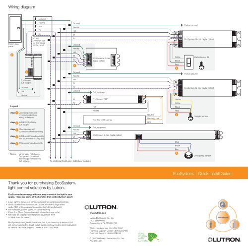
<strong>Wiring</strong> diagram<br />
Ground<br />
Neutral<br />
Hot<br />
E1<br />
E2<br />
Ground<br />
Neutral<br />
Hot<br />
E1<br />
Fixture ground<br />
Distribution<br />
panel<br />
4" x 4"<br />
Junction box<br />
or first fixture<br />
in the circuit<br />
E2<br />
Ground<br />
Neutral<br />
<strong>EcoSystem</strong> G–can digital ballast<br />
2<br />
Hot<br />
E1<br />
E2<br />
<strong>EcoSystem</strong>® K–can<br />
digital ballast<br />
White<br />
Black<br />
Wallstation or IR<br />
3<br />
1 2 3 4 5 6 7 8<br />
1<br />
Ground<br />
Neutral<br />
Red<br />
5<br />
Fixture ground<br />
<strong>EcoSystem</strong><br />
bus supply<br />
Hot<br />
E1<br />
Ground<br />
Hot<br />
Neutral<br />
E2<br />
Ground<br />
Fixture ground<br />
<strong>EcoSystem</strong> G–can digital ballast<br />
E1<br />
<strong>EcoSystem</strong> BMF<br />
Yellow<br />
Legend<br />
E2<br />
Hot<br />
White<br />
Black<br />
step<br />
step<br />
step<br />
step<br />
step<br />
1<br />
2<br />
3<br />
4<br />
5<br />
Connect power and<br />
communication bus<br />
wiring to fixtures<br />
Install <strong>EcoSystem</strong>®<br />
bus supply<br />
Check power and<br />
communication bus wiring<br />
Install sensors and controls<br />
(not shown on this diagram)<br />
Wire sensors and controls<br />
Ground<br />
Neutral<br />
Hot<br />
E1<br />
E2<br />
Neutral<br />
Eco-10® or Hi-Lume®<br />
Fixture ground<br />
<strong>EcoSystem</strong> J–can digital ballast<br />
Neutral<br />
Dimmed Hot<br />
Hot<br />
Red<br />
5<br />
Blue<br />
Black<br />
Daylight sensor<br />
Red<br />
Notes: Lamp wires not shown.<br />
Orange input used with<br />
line voltage controls only<br />
(not shown).<br />
To additional <strong>EcoSystem</strong> ballasts or modules<br />
5<br />
Occupancy sensor<br />
<strong>EcoSystem</strong>® | Quick Install Guide<br />
Thank you for purchasing <strong>EcoSystem</strong>®<br />
light control solutions by <strong>Lutron</strong>.<br />
<strong>EcoSystem</strong> is an energy-efficient way to control the light in your<br />
space. These are some of the benefits that set <strong>EcoSystem</strong> apart:<br />
• Every lighting fixture is a connection point for sensors and controls<br />
• Sensors and controls connect to fixture with low-voltage wires<br />
and a PDA-style programmer assigns them to any fixture(s)<br />
• No interfaces, power packs, or power rewiring<br />
• Class 1 or Class 2 control wiring that can be in any order<br />
• No need for separate controllers or equipment from<br />
multiple manufacturers<br />
<strong>EcoSystem</strong> is designed to be simple, but if you have any questions that<br />
are not covered in this Quick Install Guide, visit www.lutron.com/ecosystem<br />
or call the Technical Support Center at 1.800.523.9466.<br />
www.lutron.com<br />
<strong>Lutron</strong> Electronics Co., Inc.<br />
7200 Suter Road<br />
Coopersburg, PA 18036-1299<br />
World Headquarters 1.610.282.3800<br />
Technical Support Center 1.800.523.9466<br />
Customer Service 1.888.LUTRON1<br />
© 09/2009 <strong>Lutron</strong> Electronics Co., Inc.<br />
P/N 367-1400<br />
<strong>EcoSystem</strong>
<strong>EcoSystem</strong>® | Quick Install Guide<br />
Review components<br />
Start here<br />
For each system ensure you have:<br />
B<br />
At least one of these devices:<br />
These six steps ensure the quickest installation of <strong>EcoSystem</strong>.<br />
A<br />
At least one of these (may be pre-installed in the light fixtures):<br />
1. Connect power and communication bus wiring to fixtures<br />
2. Install <strong>EcoSystem</strong> bus supply<br />
3. Check power and communication bus wiring<br />
4. Install sensors and controls<br />
5. Wire sensors and controls<br />
Consult individual component installation guides<br />
for details on each step.<br />
6. When all the steps are completed and checked,<br />
call 1.800.523.9466 to schedule on-site <strong>Lutron</strong><br />
commissioning. (Allow 10 days for scheduling)<br />
Keep this document for your record.<br />
C<br />
<strong>EcoSystem</strong> G–can<br />
digital ballast<br />
<strong>EcoSystem</strong> J–can digital ballast<br />
At least one<br />
of these devices:<br />
D<br />
<strong>EcoSystem</strong> BMF and<br />
Eco-10® or Hi-lume®<br />
A programmer to make any<br />
adjustments from the standard<br />
operation of the system:<br />
<strong>EcoSystem</strong> K–can<br />
digital ballast<br />
E<br />
Daylight sensor<br />
C-SR-M1-WH<br />
Optional devices:<br />
IR receiver<br />
C-R-M1-WH<br />
Wallstation<br />
(1 button)<br />
CC-1BRL-WH<br />
Wallstation<br />
(4 button)<br />
CC-4BRL-WH<br />
If everything is wired correctly and issues persist,<br />
call 1.800.523.9466 for 24/7 technical assistance.<br />
step<br />
1<br />
Connect power and<br />
communication bus<br />
wiring to fixtures<br />
Connect power wiring (hot, neutral, ground) to each fixture.<br />
Connect bus cable (E1, E2) to each figure.<br />
Once complete, energize power to all fixtures, they should turn on to full<br />
brightness. If fixtures do not go to full brightness, check wiring and consult<br />
ballast installation guide.<br />
To additional <strong>EcoSystem</strong><br />
Ballasts or Modules<br />
*Note: Orange input used<br />
with line voltage controls<br />
only (not shown).<br />
Fixture ground<br />
White<br />
Orange<br />
Black<br />
E1<br />
E2<br />
+20V<br />
+20V<br />
+20V<br />
Common<br />
Common<br />
Common<br />
IR<br />
Occ<br />
Daylight<br />
1 2 3 4 5 6 7 8<br />
FOLD<br />
Bus supply<br />
CS-1L-CM,<br />
CS-1L-WM<br />
Programmer<br />
C-PDA-CLR<br />
Occupancy sensor<br />
(wall mounted)<br />
LOS-WDT-WH (shown)<br />
LOS-WDT-R-WH<br />
LOS-WIR-WH<br />
Checked by: Checked by: Checked by:<br />
step<br />
4<br />
Ground<br />
Neutral<br />
Hot<br />
E1<br />
E2<br />
Install sensors and controls<br />
Install sensors and wallstations as shown in the drawings.<br />
Mount daylight sensors to ceiling tiles, or bottom of pendant<br />
fixtures. Consult drawings or instruction sheets for location<br />
of the daylight sensor, occupancy sensors and wallstations.<br />
step<br />
2<br />
Install <strong>EcoSystem</strong> bus supply<br />
Connect power wiring (hot, neutral, ground) to the bus supply.<br />
Connect bus cable (E1, E2) to the bus supply.<br />
The <strong>EcoSystem</strong> bus supply will provide 18 VDC output across the<br />
E1 and E2 wires to every fixture with an <strong>EcoSystem</strong> ballast or module.<br />
step<br />
5<br />
E1<br />
E2<br />
To maximum of 64 ballasts or modules<br />
Neutral<br />
Hot (120 or 277)<br />
22AWG solid wire to the closest<br />
ballast or module. Do not exceed<br />
100 ft from sensor to ballast.<br />
Wire sensors and controls<br />
step<br />
1 2 3 4 5 6 7 8<br />
3<br />
Occupancy sensor (ceiling mounted)<br />
LOS-CUS-WH (shown)<br />
LOS-CDT-(500, 1000, 2000)-WH<br />
LOS-CDT-(500R, 1000R, 2000R)-WH<br />
LOS-CIR-(450, 1500)-WH<br />
1 2 3 4 5 6 7 8<br />
1 2 3 4 5 6 7 8 1 2 3 4 5 6 7 8<br />
1 2 3 4 5 6 7 8<br />
1 2 3 4 5 6 7 8 1 2 3 4 5 6 7 8<br />
IR handheld<br />
control<br />
C-FLRC-WH<br />
Check power and<br />
communication bus wiring<br />
Power light fixtures and bus supply.<br />
Use dip-switches on bus supply to check wiring.<br />
A B C<br />
All lights should<br />
go to a very<br />
low level. If not,<br />
check wiring.<br />
Connect only one sensor to the IR and Daylight inputs.<br />
Wire sensors to one ballast only. Sensors will be<br />
programmed to control more than one ballast.<br />
<strong>EcoSystem</strong> CFL ballasts do not have integral sensor connections.<br />
G–can with daylight sensor J–can with occupancy sensor G–can with wallstation<br />
All lights<br />
should go to<br />
full brightness.<br />
If not, check bus<br />
supply wiring.<br />
1 2 3 4 5 6 7 8<br />
Testing complete.<br />
This configuration<br />
is for standard<br />
operation.<br />
1 2 3 4 5 6 7 8 1 2 3 4 5 6 7 8<br />
Red<br />
Black<br />
White<br />
Yellow<br />
White<br />
Orange<br />
Black<br />
Red<br />
Black<br />
Blue<br />
Red<br />
Black<br />
White<br />
White<br />
Orange<br />
Black<br />
E1<br />
E2<br />
E1<br />
E2<br />
Pendant fixture<br />
Ceiling tile or fixture<br />
+20V<br />
+20V<br />
+20V<br />
Common<br />
Common<br />
Common<br />
IR<br />
Occ<br />
Daylight<br />
+20V<br />
Common<br />
IR<br />
Occ<br />
Daylight<br />
+20V<br />
+20V<br />
+20V<br />
Common<br />
Common<br />
Common<br />
IR<br />
Occ<br />
Daylight<br />
Checked by:<br />
Checked by:<br />
*Note: Orange input used with line voltage controls only (not shown).