A 3.3-V CMOS adaptive analog video line driver with ... - IEEE Xplore
A 3.3-V CMOS adaptive analog video line driver with ... - IEEE Xplore
A 3.3-V CMOS adaptive analog video line driver with ... - IEEE Xplore

You also want an ePaper? Increase the reach of your titles
YUMPU automatically turns print PDFs into web optimized ePapers that Google loves.
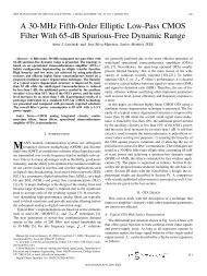
<strong>IEEE</strong> JOURNAL OF SOLID-STATE CIRCUITS, VOL. 38, NO. 6, JUNE 2003 1051<br />
A <strong>3.3</strong>-V <strong>CMOS</strong> Adaptive Analog Video Line Driver<br />
With Low Distortion Performance<br />
Narayan Prasad Ramachandran, Student Member, <strong>IEEE</strong>, Hüseyin Dinç, Student Member, <strong>IEEE</strong>, and<br />
Aydın İ. Karşılayan, Member, <strong>IEEE</strong><br />
Abstract—An <strong>analog</strong> <strong>line</strong> <strong>driver</strong> for <strong>video</strong> applications is presented.<br />
Utilizing a class-AB error amplifier structure, the design<br />
achieved 1.2–V peak-to-peak output swing <strong>with</strong> better than 42-dB<br />
<strong>line</strong>arity for frequencies up to 5 MHz. An <strong>adaptive</strong> tuning scheme<br />
for output impedance matching using peak detection is used to<br />
provide uniform performance across <strong>line</strong> impedance variations.<br />
The circuit is designed in AMI 0.5- <strong>CMOS</strong> technology and has<br />
a tuning range of 70–180 <strong>with</strong> a power consumption of about<br />
26.4 mW at 75- load.<br />
Index Terms—Adaptive circuits, class AB, <strong>CMOS</strong>, <strong>line</strong> <strong>driver</strong>.<br />
I. INTRODUCTION<br />
THE demand for information has led to the development<br />
of several low-cost high-data-rate systems. The important<br />
link between the sophisticated digital signal processing (DSP)<br />
algorithms and the <strong>analog</strong> signals riding the cable are hybrid<br />
circuits, of which the <strong>line</strong> <strong>driver</strong> is a key element. Line <strong>driver</strong>s<br />
find application in ISDN transceivers, DSL, and cable modems<br />
to drive the <strong>analog</strong> signals onto the communication channel<br />
or medium. The <strong>line</strong> <strong>driver</strong> is part of the <strong>analog</strong> front-end<br />
transmitter for a wired communication system and is <strong>analog</strong>ous<br />
to the power amplifiers in wireless transmission. Line <strong>driver</strong>s<br />
are voltage buffers that provide the necessary output current to<br />
drive the small load impedance (nominally matched to the <strong>line</strong><br />
impedance), which is nominally between 50 and 150 and<br />
varies upon the cable length, temperature, and other external<br />
effects. The main requirements of a <strong>line</strong> <strong>driver</strong> are high output<br />
swing, high <strong>line</strong>arity, good power efficiency, and matching for<br />
<strong>line</strong> impedance over process variations.<br />
The attenuation along the cable is exponentially proportional<br />
to the cable length and radius. As a result, high output swing is<br />
required so that the signal can be differentiated from the noise<br />
at the receiver end or at a repeater. Furthermore, modulation<br />
techniques such as discrete multitone (DMT) distribute information<br />
in discrete tones that can be treated as pseudorandom<br />
noise in time domain [1]. These tones add up to create high<br />
crest factor (peak-to-average voltage ratio), which can exceed<br />
the <strong>line</strong>ar range of the amplifier, causing signals to be distorted.<br />
One of the important parameters of a communication system<br />
is the bit-error rate (BER) at the receiver, which is correlated<br />
<strong>with</strong> the distortion in the <strong>analog</strong> transceiver blocks [1]. High<br />
dynamic range of the <strong>line</strong> <strong>driver</strong> ensures lower BER of the<br />
overall system. Also due to the large output swing and small<br />
load (<strong>line</strong>) impedance, high power efficiency is demanded.<br />
Manuscript received August 13, 2002; revised January 14, 2003.<br />
The authors are <strong>with</strong> the Department of Electrical Engineering, Texas A&M<br />
University, College Station, TX 77843 USA (e-mail: karsilay@ee.tamu.edu).<br />
Digital Object Identifier 10.1109/JSSC.2003.811954<br />
Usually, class-AB output stages provide best results in terms<br />
of efficiency and swing. The <strong>line</strong> impedance is subject to<br />
large variations due to loading effects, <strong>line</strong> length variation,<br />
and temperature [2]. Without matching, the reflections are<br />
not canceled at the transmitter end, which may degrade the<br />
<strong>driver</strong> performance. Thus, tuning and matching of the output<br />
impedance of the <strong>driver</strong> to the load is necessary to achieve<br />
maximum power transfer while maintaining high <strong>line</strong>arity.<br />
Several <strong>line</strong> <strong>driver</strong> architectures for different applications<br />
(Serial Bus, Video, xDSL, and ISDN) are extensively available<br />
in the literature, <strong>with</strong> emphasis on <strong>line</strong>arity, output swing,<br />
power efficiency, bandwidth, and matching. An ISDN <strong>line</strong><br />
<strong>driver</strong> [3] has been designed <strong>with</strong> 80-dB <strong>line</strong>arity and 2.5-V -<br />
(peak-to-peak) swing by trading off output swing of the buffer<br />
to the transformer ratio. An HDSL <strong>line</strong> <strong>driver</strong> <strong>with</strong> resistive<br />
feedback and Miller compensation [4] achieved 70-dB <strong>line</strong>arity<br />
and 2.4-V - swing <strong>with</strong> 30- load resistance. Using a fully<br />
differential architecture <strong>with</strong> gain tuning [5] achieves better<br />
than 47-dB <strong>line</strong>arity <strong>with</strong> a 75- load. The reported power<br />
efficiency is, however, poor. In [5]–[7] tuning schemes are<br />
utilized for gain, impedance, or quiescent current adjustment to<br />
achieve similar results over a range of operating conditions.<br />
This paper describes a <strong>CMOS</strong> <strong>line</strong> <strong>driver</strong> capable of delivering<br />
1.2-V - signal up to 5 MHz <strong>with</strong> a <strong>line</strong>arity (SFDR) of<br />
better than 0.4% across load variations from 70 to 180 . The<br />
emphasis of the design is on impedance matching, thereby maximizing<br />
power efficiency. Using an on-chip tuning scheme <strong>with</strong><br />
continuous calibration, the output impedance of the <strong>line</strong> <strong>driver</strong><br />
is matched to the <strong>line</strong> impedance, providing uniform <strong>line</strong> <strong>driver</strong><br />
performance across a range of <strong>line</strong> impedance variation.<br />
Section II out<strong>line</strong>s the principle behind impedance matching<br />
and the need for proper termination in <strong>line</strong> <strong>driver</strong> circuits. In<br />
Section III, the proposed <strong>video</strong> <strong>line</strong> <strong>driver</strong> <strong>with</strong> the associated<br />
tuning circuitry is presented. Section IV provides the experimental<br />
results from the chip, and conclusions are drawn in Section<br />
V.<br />
II. BASIC PRINCIPLE<br />
While transmitting high-speed data over communication<br />
channels, proper matching of impedance at both the <strong>driver</strong><br />
and the receiver end is necessary to ensure low BER. When a<br />
signal encounters a mismatch in impedance due to improper<br />
termination, reflections or echoes appear on the <strong>line</strong>, whose<br />
characteristics depend on the <strong>line</strong> length and signal frequency<br />
[9]. Such reflections distort the information and reduce the bit<br />
rate of the system.<br />
A simple solution commonly used to eliminate reflections at<br />
the <strong>driver</strong> end is to use series termination as shown in Fig. 1,<br />
0018-9200/03$17.00 © 2003 <strong>IEEE</strong>
1052 <strong>IEEE</strong> JOURNAL OF SOLID-STATE CIRCUITS, VOL. 38, NO. 6, JUNE 2003<br />
Fig. 1.<br />
Series termination at <strong>line</strong> <strong>driver</strong> end.<br />
Fig. 2.<br />
System block diagram <strong>with</strong> the <strong>line</strong> <strong>driver</strong> and tuning loop.<br />
where denotes the <strong>line</strong> impedance of the cable. The resistance<br />
is chosen such that the sum of the output resistance<br />
of the <strong>line</strong> <strong>driver</strong> and series resistor ( equals the nominal<br />
<strong>line</strong> impedance . However, this scheme has several inherent<br />
disadvantages. Process variations cause the output resistance<br />
of the <strong>line</strong> <strong>driver</strong> to vary, requiring the termination resistor to<br />
be changed accordingly. In addition to this, the <strong>line</strong> impedance<br />
is also subject to variations. A second serious drawback is the<br />
voltage drop across the resistor. If the output resistance is neglected,<br />
is equal to , in which case half the voltage<br />
is lost across . Consequently, the signal swing requirement<br />
is now doubled as compared to the unterminated case, <strong>with</strong> the<br />
<strong>line</strong>arity and power-supply conditions unchanged.<br />
To overcome these drawbacks, the design approach is to<br />
match the output impedance of the buffer directly to the <strong>line</strong><br />
impedance, thereby eliminating the need for series termination<br />
and avoiding the associated voltage drop. Impedance matching<br />
is done using a topology wherein, when the output voltage is<br />
equal to the input, the output resistance is matched to the <strong>line</strong>.<br />
This scheme has the advantage that it can adjust to external <strong>line</strong><br />
as well as internal process variations.<br />
The origin of the architecture presented in this paper is the<br />
class-A <strong>adaptive</strong> <strong>line</strong> <strong>driver</strong> [7], [8] <strong>with</strong> a tuning scheme which<br />
utilizes dc operating point correction for impedance matching.<br />
This topology, however, is limited in its power efficiency due to<br />
the class-A operation. In order to provide 1.2-V - swing, a dc<br />
current of at least 8–10 mA is required to provide the necessary<br />
dc operating point at the output. By extending the topology to<br />
a push-pull class-AB structure, the efficiency can be improved<br />
significantly. A robust tuning scheme employing peak detection<br />
is combined <strong>with</strong> the <strong>line</strong> <strong>driver</strong> to provide consistent performance<br />
across varying <strong>line</strong> impedance.<br />
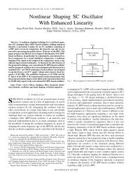
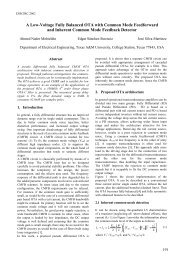
Fig. 2 shows the overall block diagram of the proposed <strong>video</strong><br />
<strong>line</strong> <strong>driver</strong> <strong>with</strong> the tuning loop consisting of the peak-to-peak<br />
detectors and a differential difference amplifier. Using the<br />
peak-to-peak detectors, positive and negative peak voltages<br />
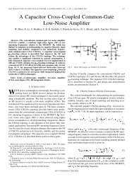
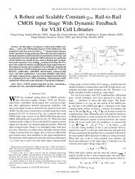
Fig. 3. Line <strong>driver</strong> schematic <strong>with</strong> the error amplifiers, class-AB output stage,<br />
and tunable current mirrors.<br />
of the input and the output are extracted. With the differential<br />
difference amplifier (DDA) and the four outputs of the peak detector<br />
block, the control voltage is obtained, completing<br />
the feedback loop. This control voltage is used to adjust the<br />
mirroring factor of the tunable current mirrors in the <strong>line</strong> <strong>driver</strong>.<br />
When the <strong>line</strong> impedance increases, the current delivered is<br />
decreased and vice versa, such that the same output voltage<br />
as the input is obtained. When the input and output voltages<br />
are forced to be equal, the output resistance of the <strong>driver</strong> is<br />
matched to that of the <strong>line</strong>.<br />
III. LINE DRIVER DESIGN<br />
Although designed for specific <strong>line</strong> impedance, <strong>line</strong> <strong>driver</strong>s<br />
need to adapt themselves to variations in <strong>line</strong> characteristic<br />
impedance; otherwise, the <strong>line</strong>arity and the output swing of the<br />
<strong>line</strong> <strong>driver</strong> will be adversely affected. In this paper, a class-AB<br />
output stage <strong>with</strong> controlled output impedance is used as a <strong>line</strong><br />
<strong>driver</strong> architecture wherein the mirroring factor is adjustable.<br />
The mirroring factor is adjusted through the feedback loop and<br />
controls the gain and output resistance of the <strong>driver</strong>.<br />
A. Class-AB Output Stage<br />
The <strong>line</strong> <strong>driver</strong> schematic as shown in Fig. 3 consists of a<br />
class-AB output stage <strong>with</strong> error amplifiers whose output resistance<br />
is controllable. Although the quiescent current control is<br />
an important design constraint [10], [11], the <strong>line</strong> <strong>driver</strong> proposed<br />
in this paper lacks a quiescent current stabilizer circuit<br />
since the main motivation in this design is to apply impedance<br />
tuning to a class-AB buffer. The quiescent current is set by the<br />
gate-to-source voltages of M and M , which is further controlled<br />
by the error amplifiers in feedback. The error amplifiers<br />
are designed <strong>with</strong> low gain so that offsets or mismatch do not<br />
cause large variations in the quiescent current.
<strong>IEEE</strong> JOURNAL OF SOLID-STATE CIRCUITS, VOL. 38, NO. 6, JUNE 2003 1053<br />
In Fig. 3, the dc voltage at the nodes and are identical<br />
to the input, assuming zero offset voltages for the error<br />
amplifiers. Any mismatch between the mirroring ratios of the<br />
half-circuits and the input offsets of the error amplifiers cause<br />
small dc currents to flow across the bridge resistance. Error amplifiers<br />
are designed <strong>with</strong> sufficient gain to ensure that the signal<br />
is copied to the node . The signal current ( )is<br />
mirrored by the transistors M –M and M –M to the output<br />
stage, summed at the node and flows into . The dc operating<br />
point and the large signal operation of the <strong>line</strong> <strong>driver</strong> is<br />
unaffected by the bridge resistance, which sees only the signal<br />
reflections from the <strong>line</strong>. The overall buffer gain and the output<br />
resistance are given in (1) and (2), respectively. Under the<br />
assumption that transistors M –M are in saturation, the following<br />
expressions are valid<br />
(1)<br />
(2)<br />
(a)<br />
The ratio defines the mirroring factor of transistor pairs<br />
M –M and M –M and is a function of both the transistor dimensions<br />
and gate-to-source voltages (V ), while is a ratio<br />
of device dimensions. Thus the value of equal to is a special<br />
case, when the <strong>line</strong> resistance is . Furthermore, the<br />
variable resistor controls the source voltage ( of transistors<br />
M and M . The tuning loop enforces the output voltage<br />
to be equal to the input, which results in the condition given by<br />
(3)<br />
(4)<br />
(5)<br />
where and are fixed by design to be 75 and 12, respectively.<br />
When increases, the mirroring ratio decreases<br />
to satisfy the condition in (5). Substituting (5) in (2) results in<br />
the output resistance being equal to the <strong>line</strong> resistance as in<br />
Thus, using this <strong>line</strong> <strong>driver</strong> architecture, when the output is<br />
made equal to the input, the output resistance of the <strong>driver</strong> is<br />
equal to that of the <strong>line</strong> and a proper <strong>line</strong> termination is achieved.<br />
The mirroring ratio is mainly determined by the variable resistance<br />
which is controlled through the feedback loop. If<br />
the gate-to-source voltage of the transistors M –M and<br />
M –M are the same, the mirroring ratio is determined by the<br />
transistor aspect ratios (M –M and M –M ) and is equal to .<br />
This occurs when the load resistance is the same as .<br />
When the load resistance decreases, the signal current is<br />
increased in order to maintain the same output swing as the<br />
input. This is achieved by increasing the resistance , which<br />
consequently increases and decreases . However, the<br />
gate-to-source voltages of M and M do not change. This is<br />
because the source voltage tracks the gate voltage .On<br />
(6)<br />
Fig. 4.<br />
(b)<br />
(a) Positive-half (OTA1) and (b) negative-half (OTA2) error amplifiers.<br />
the other hand, and increase, which results in an<br />
increase in the mirroring ratio as seen from (4).<br />
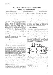
B. Transconductors<br />
Positive-half (OTA1) and negative-half (OTA2) error amplifiers<br />
(Fig. 4) are basic differential amplifiers <strong>with</strong> n- and p-type<br />
<strong>driver</strong>s, respectively. Using such complementary structure is<br />
crucial to handle large signal swings for both the negative<br />
and positive cycle. The differential amplifier <strong>with</strong> nMOS<br />
<strong>driver</strong>s can handle input common mode signals as high as<br />
which makes it a good positive-half<br />
error amplifier. On the other hand, the amplifier <strong>with</strong><br />
pMOS <strong>driver</strong>s can handle input common-mode signals as low<br />
as<br />
, which makes it appropriate as<br />
a negative-half error amplifier.<br />
The dc gain of the error amplifiers is around 30–35 dB. Low<br />
gain causes error in signal voltage when copied from to<br />
and then to the output . On the other hand, high gain causes
1054 <strong>IEEE</strong> JOURNAL OF SOLID-STATE CIRCUITS, VOL. 38, NO. 6, JUNE 2003<br />
large variations in gate-to-source voltages in the presence of<br />
offset and mismatch [12]. This results in a large increase in the<br />
quiescent current and distortion. The gain-bandwidth product<br />
of the transconductors is greater than 300 MHz, which ensures<br />
negligible phase shift from input to output, in the frequency<br />
band of interest (10 kHz to 5 MHz). This condition ensures a<br />
robust tuning scheme through the comparison of the input and<br />
output envelopes, even <strong>with</strong> a simple peak detector. An important<br />
concern is the combined input offsets of the error amplifiers<br />
when used in closed loop. This affects the dc node voltage at<br />
and and can cause considerable output offset and quiescent<br />
current variations.<br />
C. Linearized Variable Resistor<br />
In the <strong>line</strong> <strong>driver</strong> of Fig. 3, the signal current in the intermediate<br />
stage (M –M ) is fixed at . Thus, the mirroring<br />
ratio is adjusted by the tuning loop to deliver the appropriate<br />
current to the output (M –M ) stage in a way that will maintain<br />
the unity gain of the buffer across varying <strong>line</strong> conditions. Resistor<br />
, implemented as a poly-resistor in parallel <strong>with</strong> an<br />
nMOS/pMOS device as shown in Fig. 5(a) and (b). The resistance<br />
value can be adjusted through , which is generated<br />
from the control voltage as shown in Fig. 5(c). The gate<br />
voltage of the MOS transistors (M /M ) controls the effective<br />
resistance . This current is mirrored to the output and<br />
flows through . In order to eliminate the non<strong>line</strong>arity of the<br />
resistor, the source of the transistors are biased <strong>with</strong><br />
(7)<br />
(a)<br />
(b)<br />
Since the transistors operate in the triode region, ignoring higher<br />
order effects, this biasing scheme reduces the non<strong>line</strong>arity of<br />
the resistor. and in (7) and (8) are the drain current and<br />
gate–source voltage of M and M , respectively.<br />
(8)<br />
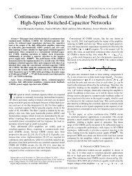
D. Peak-to-Peak Detector and DDA<br />
In order to generate the control voltage , a peak-to-peak<br />
detector circuit, as in Fig. 6, in combination <strong>with</strong> a DDA shown<br />
in Fig. 7 is utilized. The detector circuit consists of two circuits,<br />
one each for the positive and negative peak values. The first<br />
stage acts as a peak detector, wherein the capacitances and<br />
are charged to the positive and negative peaks quickly and<br />
discharged at a very slow rate by a small current. The second<br />
stage reduces the dc shift from the first stage so that the dc point<br />
at the output is close to the input and applies a second peak<br />
detection to the output of the first stage, further reducing the<br />
ripple. The transient response of the peak-to-peak detector for<br />
a 1-V - input signal at 2 MHz is shown in Fig. 8(a) <strong>with</strong> the<br />
positive and negative peak signals. The ripple in the peak values<br />
is about 30 mV. By using smaller discharge currents, the ripple<br />
can be reduced.<br />
Two identical peak-to-peak detectors are used for the inputs<br />
and the outputs. Systematic mismatch between the positive or<br />
negative peak detector circuits for the inputs and outputs is not<br />
of much concern since they are cancelled at the inputs of the<br />
(c)<br />
Fig. 5. Tunable resistor implementation. (a) P-type variable resistor <strong>with</strong><br />
<strong>line</strong>arization. (b) N-type variable resistor <strong>with</strong> <strong>line</strong>arization. (c) Resistor control<br />
through I .<br />
differential difference amplifier. However, random mismatches<br />
including wafer gradients can offset the tuning process, causing<br />
poorer matching. The positive and negative peak values of the<br />
input are available at and , which are not significantly<br />
dependent on the dc offset as shown in Fig. 8(b). Two<br />
such peak detector circuits are used to obtain the four peak voltages<br />
of the <strong>line</strong> <strong>driver</strong> input and output ( ,<br />
and ).
<strong>IEEE</strong> JOURNAL OF SOLID-STATE CIRCUITS, VOL. 38, NO. 6, JUNE 2003 1055<br />
Fig. 6.<br />
Peak-to-peak detector.<br />
Fig. 7.<br />
Differential difference amplifier.<br />
When a sinusoid is applied to the <strong>line</strong> <strong>driver</strong> input, the instantaneous<br />
output voltage may be different from the input depending<br />
on the <strong>line</strong> conditions. The peak-to-peak information of<br />
the input and output are detected and the control voltage ( )<br />
is computed by the DDA. The tuning current ( ) further generated<br />
from the control voltage adjusts the variable resistor<br />
suitably to increase or decrease the mirroring ratio, thereby completing<br />
the tuning loop. When the output voltage is less than the<br />
input, the mirroring ratio is increased and vice versa. Thus, for a<br />
range of <strong>line</strong> impedance variations, the <strong>line</strong> <strong>driver</strong> gain is unity<br />
and the output impedance matched to that of the <strong>line</strong>.<br />
IV. EXPERIMENTAL RESULTS<br />
The circuit of Fig. 3 along <strong>with</strong> the tuning loop is integrated<br />
in a standard 0.5- m <strong>CMOS</strong> process. The active area is about<br />
0.22 mm . The input signal for tuning purposes is a 1-V - sinusoid<br />
at 5 MHz. The choice of the test signal is determined by the
1056 <strong>IEEE</strong> JOURNAL OF SOLID-STATE CIRCUITS, VOL. 38, NO. 6, JUNE 2003<br />
(a)<br />
(b)<br />
Fig. 8.<br />
(a) Transient response of the peak-to-peak detector. (b) Output peak-to-peak voltage versus input peak voltage for different input offsets.<br />
tuning loop. The input amplitude is chosen as high as possible,<br />
<strong>with</strong>out saturating the <strong>line</strong> <strong>driver</strong> (typically 1–1.4 V - . This<br />
is because the peak detector does not give the exact peak value<br />
and has a limited input range between 0.4 and 1.2 V - . As a result,<br />
for small input voltages (around 200 mV), the tuning loop<br />
does not converge properly. The frequency of the signal should<br />
be close to the maximum operating frequency of <strong>line</strong> <strong>driver</strong> so<br />
as to filter out the signal components and obtain a steady-state<br />
control voltage . Simulation results indicate the overall settling<br />
time response of the tuning loop to be about 50 s.<br />
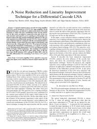
The <strong>line</strong> <strong>driver</strong> gain response <strong>with</strong> and <strong>with</strong>out impedance<br />
matching is shown in Fig. 9. In the absence of tuning, the output<br />
voltage exceeds or is less than the input. The signal current supplied<br />
to the load is a fixed multiple of the current generated by<br />
M and M (determined by resistance ), irrespective of<br />
the <strong>line</strong> impedance. However, in the case of tuning, variable current<br />
is provided to the load by adjusting the mirroring ratio ,<br />
thereby forcing the output to follow the input. Thus, as load<br />
resistance increases, current is decreased to achieve constant<br />
output. The tuning range in this case varies from 70 to 180<br />
for less than 3% error between input and output voltage.<br />
While impedance matching to provide uniform performance<br />
is essential, the <strong>line</strong>arity of the <strong>line</strong> <strong>driver</strong> cannot be sacrificed.<br />
This imposes additional constraints to the design in terms of distortion<br />
specifications. Fig. 10 shows the distortion performance<br />
for 75- <strong>line</strong> impedance and 1-V - output at 2 MHz measured<br />
using an HP4395 spectrum analyzer. The second harmonic is<br />
lower than 45 dB compared <strong>with</strong> the input and improves <strong>with</strong><br />
lower frequency. Fig. 11 shows the <strong>line</strong>arity measurement as<br />
a function of frequency for three different <strong>line</strong> resistances at
<strong>IEEE</strong> JOURNAL OF SOLID-STATE CIRCUITS, VOL. 38, NO. 6, JUNE 2003 1057<br />
Fig. 12. Linearity as a function of input voltage for different R .<br />
Fig. 9. Gain (V =V ) as function of <strong>line</strong> resistance R <strong>with</strong> and <strong>with</strong>out tuning.<br />
(a)<br />
Fig. 10.<br />
Frequency spectrum at 75- load, 1 V - , 2-MHz input.<br />
(b)<br />
Fig. 11. Linearity as a function of frequency for different R .<br />
Fig. 13. AC response of the <strong>line</strong> <strong>driver</strong> for <strong>line</strong> resistance R of 75, 110, and<br />
150 . (a) 10 kHz to 15 MHz. (b) 10 kHz to 5 MHz.<br />
1V - , while Fig. 12 shows <strong>line</strong>arity against input voltage for<br />
500-kHz input frequency. The overall <strong>line</strong> <strong>driver</strong> performance<br />
is better than 42 dB over the frequency range from 10 kHz to<br />
5 MHz, <strong>with</strong> 1.2-V - output.
1058 <strong>IEEE</strong> JOURNAL OF SOLID-STATE CIRCUITS, VOL. 38, NO. 6, JUNE 2003<br />
TABLE I<br />
SUMMARY OF LINE DRIVER PERFORMANCE<br />
Table I summarizes the experimental results of the <strong>line</strong> <strong>driver</strong>.<br />
Across a wide range of <strong>line</strong> impedance, the <strong>line</strong>arity (SFDR) has<br />
been shown to be consistently better than 42 dB for 1.2-V swing<br />
and gain response is unity <strong>with</strong> an error of less than 3%. The<br />
power consumption is 27 mW, 30% of which is consumed by<br />
the tuning loop. The <strong>line</strong> <strong>driver</strong> can be easily scaled for different<br />
supply voltages from 3 to 6 V. The input signal amplitude has<br />
to be correspondingly scaled to achieve best results. The chip is<br />
fabricated in AMI 0.5- m <strong>CMOS</strong> three-metal two-poly process.<br />
The die photo is shown in Fig. 14.<br />
V. CONCLUSION<br />
A compact <strong>3.3</strong>-V 0.5- m <strong>CMOS</strong> <strong>analog</strong> <strong>line</strong> <strong>driver</strong> is<br />
presented. The main features of this <strong>line</strong> <strong>driver</strong> are the class-AB<br />
output stage <strong>with</strong> the controlled output impedance and the<br />
tuning scheme as compared <strong>with</strong> the previous architecture<br />
[7]. This <strong>line</strong> <strong>driver</strong> topology provides proper <strong>line</strong> termination<br />
while eliminating the drawbacks associated <strong>with</strong> series <strong>line</strong><br />
termination such as voltage drop across the matching resistor.<br />
The tuning scheme, simple yet robust, provides wide matching<br />
range from 70 to 180 . A maximum power efficiency of 16%<br />
is achieved <strong>with</strong> an output voltage range of 0.8 V. Linearity<br />
can be improved by making the <strong>line</strong> <strong>driver</strong> pseudo- or fully<br />
differential and by implementing a quiescent current control<br />
loop.<br />
Fig. 14.<br />
Line <strong>driver</strong> chip microphotograph.<br />
The gain versus frequency response was measured using<br />
an HP4395 network analyzer. The ac response is shown in<br />
Fig. 13(a) for the <strong>line</strong> <strong>driver</strong> at 75-, 110-, and 150- <strong>line</strong><br />
impedance. The bandwidth in all cases is around 15 MHz due<br />
to the loading of the output stage. The gain is one in the case of<br />
75- and 150- load, while it is 0.98 at 110 , an error of 2%.<br />
The gain flatness is accurate to 0.1% variation up to 5 MHz as<br />
seen in Fig. 13(b).<br />
REFERENCES<br />
[1] B. Day, S. Wurcer, and T. Hoffman. (2000, Feb.) Bridging ADSL <strong>line</strong><br />
<strong>driver</strong> challenges. Electron. Eng. [On<strong>line</strong>]. Available: http://www.eetasia.com/ARTICLES/2000FEB/2000FEB01_NTEK_TA.PDF<br />
[2] D. A. Johns and D. Essig, “Integrated circuits for data transmission<br />
over twisted-pair channels,” <strong>IEEE</strong> J. Solid-State Circuits, vol. 32, pp.<br />
398–406, Mar. 1997.<br />
[3] H. Khorramabadi, “A <strong>CMOS</strong> <strong>line</strong> <strong>driver</strong> <strong>with</strong> 80-dB <strong>line</strong>arity for ISDN<br />
applications,” <strong>IEEE</strong> J. Solid-State Circuits, vol. 27, pp. 539–544, Apr.<br />
1992.<br />
[4] M. S. Kappes, “A 3-V <strong>CMOS</strong> low-distortion class-AB <strong>line</strong> <strong>driver</strong> suitable<br />
for HDSL applications,” <strong>IEEE</strong> J. Solid-State Circuits, vol. 35, no.<br />
3, pp. 371–376, Mar. 2000.<br />
[5] R. Mahadevan and D. A. Johns, “A differential 160-MHz self-terminating<br />
<strong>adaptive</strong> <strong>CMOS</strong> <strong>line</strong> <strong>driver</strong>,” <strong>IEEE</strong> J. Solid-State Circuits, vol.<br />
35, pp. 1889–1894, Dec. 2000.<br />
[6] H. Casier, P. Wouters, B. Graindourze, and D. Sallaerts, “A <strong>3.3</strong>-V lowdistortion<br />
ISDN <strong>line</strong> <strong>driver</strong> <strong>with</strong> a novel quiescent current control circuit,”<br />
<strong>IEEE</strong> J. Solid-State Circuits, vol. 33, pp. 1130–1133, July 1998.<br />
[7] B. Nauta and M. B. Dijkstra, “Analog <strong>line</strong> <strong>driver</strong> <strong>with</strong> <strong>adaptive</strong><br />
impedance matching,” <strong>IEEE</strong> J. Solid-State Circuits, vol. 33, pp.<br />
1992–1998, Dec. 1998.<br />
[8] S. Baker and E. Swanson, “Amplifier <strong>with</strong> controlled output<br />
impedance,” U.S. Patent 5 121 080, June 9, 1992.<br />
[9] J. Vo, “A comparison of differential termination techniques,” National<br />
Semiconductor, Santa Clara, CA, Appl. Note 903, Aug. 1993.<br />
[10] K. E. Brehmer and J. A. Wieser, “Large swing <strong>CMOS</strong> operational amplifiers,”<br />
<strong>IEEE</strong> J. Solid-State Circuits, vol. SC-18, pp. 624–629, Dec.<br />
1983.<br />
[11] B. Sekerkiran, “A compact rail-to-rail output stage for <strong>CMOS</strong> operational<br />
amplifiers,” <strong>IEEE</strong> J. Solid-State Circuits, vol. 34, pp. 107–110,<br />
Jan. 1999.<br />
[12] P. R. Gray, P. J. Hurst, S. H. Lewis, and R. G. Meyer, Analysis and Design<br />
of Analog Integrated Circuits. New York: Wiley, 2001.