Bandwidth enhancement of multi-stage amplifiers using active ...
Bandwidth enhancement of multi-stage amplifiers using active ...
Bandwidth enhancement of multi-stage amplifiers using active ...

Create successful ePaper yourself
Turn your PDF publications into a flip-book with our unique Google optimized e-Paper software.
BANDWIDTH ENHANCEMENT OF MULTI-STAGE<br />
AMPLIFIERS USING ACTIVE FEEDBACK<br />
M. Reza Samadi, AydÕn ø. KarúÕlayan and Jose Silva-Martinez<br />
Texas A&M University<br />
Department <strong>of</strong> Electrical Engineering<br />
College Station, TX, 77843-3128, Email: samadi@ee.tamu.edu<br />
ABSTRACT<br />
A new topology for wideband <strong>multi</strong><strong>stage</strong> <strong>amplifiers</strong> (MA) is<br />
introduced. The proposed method uses <strong>active</strong> negative feedback<br />
in a chain <strong>of</strong> <strong>amplifiers</strong> to extend the bandwidth and improve<br />
gain-bandwidth product. The topology has several advantages<br />
such as having capability <strong>of</strong> widening bandwidth as the number<br />
<strong>of</strong> <strong>stage</strong> increases and enhancing bandwidth by several times that<br />
<strong>of</strong> the dominant pole <strong>of</strong> each <strong>stage</strong>. To verify the performance <strong>of</strong><br />
topology, an 8-<strong>stage</strong> amplifier in 0.35µm CMOS was designed,<br />
where more than 2.8GHz bandwidth and 40dB gain were<br />
obtained from simulations.<br />
1. INTRODUCTION<br />
For both data amplification and clock distribution, <strong>multi</strong><strong>stage</strong><br />
<strong>amplifiers</strong> (MA) must have high gain and wide bandwidth with<br />
frequency response ranging from DC to <strong>multi</strong>-gigahertz-band<br />
frequencies. A conventional MA is composed <strong>of</strong> n cascaded<br />
amplifier <strong>stage</strong>s such that each <strong>stage</strong> is presented as a transfer<br />
function <strong>of</strong> g j (s) with a DC gain <strong>of</strong> G. To simplify, let us assume<br />
ω G<br />
p<br />
g ( s)<br />
=<br />
j<br />
s + ω<br />
Then the overall DC gain and the bandwidth <strong>of</strong> the MA are<br />
obtained by [1]<br />
n<br />
G<br />
T<br />
= G<br />
2 1 / n<br />
≈ −<br />
bw<br />
ω p<br />
1<br />
p<br />
(1)<br />
ω (2)<br />
Increasing n decreases ω bw , whereas enlarging the bandwidth <strong>of</strong><br />
each <strong>stage</strong> increases the overall bandwidth <strong>of</strong> MA. Several<br />
techniques have been used to increase the speed <strong>of</strong> <strong>amplifiers</strong><br />
[2]-[7]. One <strong>of</strong> the methods to improve bandwidth is <strong>using</strong> local<br />
feedback [2]-[4]. Some techniques, such as capacitance and<br />
inductance peaking, enhance the bandwidth by placing a peak in<br />
the transfer function at high frequencies (these will be referred as<br />
peaking techniques). Active feedback [2]-[3] uses peaking<br />
technique to improve the bandwidth <strong>of</strong> the amplifier by reducing<br />
feedback at high frequencies. In previously reported methods [2]-<br />
[7], extending the bandwidth <strong>of</strong> one <strong>stage</strong> broadens the overall<br />
bandwidth <strong>of</strong> MA. However, the combination <strong>of</strong> the poles <strong>of</strong> all<br />
<strong>stage</strong>s degrades the overall bandwidth such that ω bw is always<br />
less than the bandwidth <strong>of</strong> each <strong>stage</strong>.<br />
A meaningful definition for performance <strong>of</strong> an n-<strong>stage</strong> MA is the<br />
gain-bandwidth product <strong>of</strong> a single <strong>stage</strong> [8] (GBP 1 ), which can<br />
be written as:<br />
1<br />
( Overall Gain ) × (3 dB )<br />
GBP1 = n − bandwidth (3)<br />
The GBP 1 and total GBP (GBP T ) for an n-<strong>stage</strong> conventional<br />
MA, when all <strong>stage</strong>s are designed as in Eq. (1), are obtained by<br />
2 1/<br />
n<br />
GBP=<br />
Gω 1<br />
(4)<br />
−<br />
1 p<br />
n<br />
2 1/<br />
n<br />
GBPT<br />
= G ω<br />
p<br />
−1<br />
(5)<br />
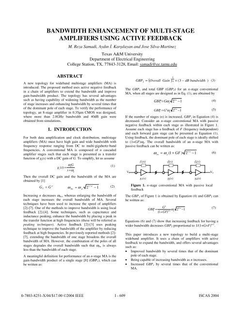
If the number <strong>of</strong> <strong>stage</strong>s (n) is increased, GBP 1 in Equation (4) is<br />
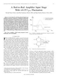
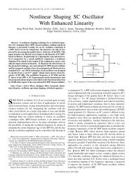
decreased. Consider an n-<strong>stage</strong> conventional MA with passive<br />
negative feedback within each <strong>stage</strong> as illustrated in Figure 1.<br />
Assume each <strong>stage</strong> has a feedback <strong>of</strong> F (frequency independent)<br />
and each forward gain <strong>stage</strong> can be presented as Equation (1).<br />
Using feedback, the dominant pole <strong>of</strong> each <strong>stage</strong> is ideally shifted<br />
to (1+GF)ω p . The overall bandwidth <strong>of</strong> an n-<strong>stage</strong> MA with<br />
passive feedback can be written as:<br />
V i<br />
+<br />
-f 1(s)<br />
1/ n<br />
ω ≈ ω (1 + GF ) 2 −1<br />
(6)<br />
bw<br />
p<br />
Figure 1. n-<strong>stage</strong> conventional MA with passive local<br />
feedback<br />
The GBP 1 <strong>of</strong> Figure 1 is obtained by Equation (4) and GBP T can<br />
be written as:<br />
GBP<br />
-f j(s)<br />
+<br />
+<br />
g 1(s) g j(s) g n(s)<br />
n<br />
G<br />
1/ n<br />
ω 2 −1<br />
n 1 p<br />
(1 + GF)<br />
= T<br />
−<br />
-f n(s)<br />
Equations (6) and (7) show that increasing feedback for having a<br />
wider bandwidth decreases GBP T proportional to 1/(1+G×F) n-1 .<br />
This paper introduces a new topology to build a <strong>multi</strong>-<strong>stage</strong><br />
wideband amplifier. It uses a chain <strong>of</strong> <strong>amplifiers</strong> with <strong>active</strong><br />
feedback to expand the bandwidth, and <strong>of</strong>fers several advantages<br />
such as:<br />
• Improved bandwidth by several times that <strong>of</strong> the dominant<br />
pole <strong>of</strong> each <strong>stage</strong>.<br />
• Being capable <strong>of</strong> increasing bandwidth as n increases.<br />
• Increased GBP 1 by several times that <strong>of</strong> the conventional<br />
MA.<br />
V o<br />
(7)
• Being capable <strong>of</strong> increasing overall gain-bandwidth product<br />
in comparison with the MA with local passive feedback for<br />
the same bandwidth.<br />
To validate the proposed topology, an 8-<strong>stage</strong> MA in 0.35µm<br />
CMOS process was designed and simulated. Section II presents<br />
the new topology or chained-feedback <strong>multi</strong><strong>stage</strong> amplifier<br />
(CMA). Circuit simulation results are presented in Section III.<br />
Finally, summary <strong>of</strong> the results and outline <strong>of</strong> the work are given.<br />
2. CHAINED FEEDBACK TOPOLOGY<br />
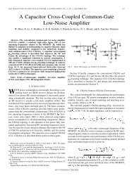
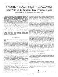
Figure 2 shows the proposed n-<strong>stage</strong> CMA topology, where<br />
<strong>active</strong> feedback is used between <strong>stage</strong>s. The overall structure is<br />
composed <strong>of</strong> n amplifier <strong>stage</strong>s g 1 (s) ,…, g n (s) with <strong>active</strong><br />
feedback gains f 1 (s) ,…, f n (s). The outputs <strong>of</strong> forward gain <strong>stage</strong>s,<br />
g j (s), and feedback <strong>stage</strong>s, -f j (s), are added together. For<br />
simplicity, assume that the amplifier blocks in Figure 2 have a<br />
single dominant pole and can be represented as in Equation (1)<br />
and feedback gains can be given as<br />
V i<br />
g 1(s)<br />
f<br />
ω F<br />
p<br />
( s) =<br />
(8)<br />
j<br />
s + ωp<br />
-f 2(s)<br />
-f j(s) -f n(s)<br />
-f 1(s) -f j-1(s) -f n-1(s) 0<br />
+ + +<br />
g 2(s) g 3(s)<br />
g j(s)<br />
+ + +<br />
g j+1(s) g n(s)<br />
Figure 2. Scheme <strong>of</strong> an n-<strong>stage</strong> CMA<br />
V o<br />
H<br />
ω<br />
2 2<br />
dc n1<br />
n2<br />
2<br />
1 n1<br />
n1<br />
2 n2<br />
n2<br />
2<br />
2 2<br />
2<br />
( s + ζ ω s + ω )( s + 2ζ<br />
ω s + ω )<br />
where ω n1 , ω n2 , ζ 1 , ζ 2 and an overall DC gain are<br />
ω<br />
(12)<br />
ω<br />
n1 = ω<br />
p<br />
1+<br />
0. 38GF<br />
ω<br />
n2 =ω<br />
p<br />
1+<br />
2. 62GF<br />
(13)<br />
−0.<br />
5<br />
−0.<br />
5<br />
ζ = ( 1+<br />
0. GF) = ( 1+<br />
2. GF) 1<br />
38<br />
ζ<br />
2<br />
62<br />
(14)<br />
4<br />
( G )<br />
( )<br />
[ 1 + 3GF<br />
GF ]<br />
2<br />
H dc<br />
=<br />
+<br />
(15)<br />
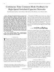
Since ω n s and ζs are different for both sections, each 2 nd -order<br />
transfer function has a peak at different frequencies. Matlab<br />
simulation <strong>of</strong> the transfer function <strong>of</strong> 4-<strong>stage</strong> CMA and two 2 nd -<br />
order functions (@ F=1) for Gs <strong>of</strong> 2.3 and 6.1, respectively, are<br />
illustrated in Figure 3. The peak <strong>of</strong> one <strong>of</strong> the 2 nd -order functions<br />
is placed where the other 2 nd -order function is decreasing. For<br />
small Gs, the –3dB frequency <strong>of</strong> CMA is determined by the –3dB<br />
frequency <strong>of</strong> the first 2 nd -order function. Increasing DC gain <strong>of</strong><br />
forward <strong>stage</strong>s (G) increases the ripple <strong>of</strong> the overall function<br />
and pushes the –3dB frequency to higher frequencies and extends<br />
the bandwidth. Increasing DC loop gain widens the bandwidth<br />
up to the point where the first 2 nd -order function produces a peak<br />
<strong>of</strong> more than 1.5dB.<br />
AC Response<br />
G=6.1<br />
To explain how CMA uses the peaking technique to widen the<br />
bandwidth, let us consider n=2, so that there is only feedback<br />
from the second amplifier to the first one. This two-<strong>stage</strong> CMA<br />
has a 2 nd -order transfer function given by<br />
s<br />
2<br />
+<br />
H<br />
ω<br />
2<br />
dc n<br />
2<br />
2ζω<br />
s + ω<br />
n n<br />
where the natural frequency, damping factor, DC gain and<br />
bandwidth are given by<br />
−0.<br />
5<br />
ω = ω 1 GF<br />
ζ = ( 1 + GF ) (10)<br />
n p<br />
+<br />
2<br />
G<br />
H dc<br />
= 1+<br />
GF<br />
ω<br />
bw<br />
2<br />
4 2<br />
= ω 1−<br />
2ζ<br />
+ 4ζ<br />
− 4ζ<br />
+ 2<br />
n<br />
(9)<br />
(11)<br />
For the underdamped case (ζ1) ω bw can be<br />
improved up to 2.69ω p , while the peak gain is less than 1.5dB<br />
(for GF≤ 3.34). In fact, <strong>using</strong> feedback mostly decreases H dc<br />
rather than increasing the bandwidth, i.e., GBP T decreases more<br />
as the bandwidth is widened.<br />
2.1 <strong>Bandwidth</strong> <strong>of</strong> CMA<br />
Transfer function <strong>of</strong> a 4-<strong>stage</strong> CMA is a 4 th -order function. It can<br />
be presented as a product <strong>of</strong> two 2 nd -order transfer functions as:<br />
Overall transfer function<br />
First 2 nd -order<br />
Second 2 nd -order .-.-<br />
Frequency/ ω p<br />
G=2.3<br />
Figure 3. Matlab plot <strong>of</strong> magnitude <strong>of</strong> two 2 nd -order<br />
transfer functions and the overall function <strong>of</strong> 4-<strong>stage</strong><br />
CMA<br />
-f 2(s)<br />
-f 4(s)<br />
-f 1(s) 0 -f 3(s)<br />
0<br />
(a)<br />
V i + + + + V o<br />
g 1(s) g 2(s) g 3(s) g 4(s)<br />
V i<br />
g 1(s)<br />
-f 1(s)<br />
-f 2(s)<br />
+ + +<br />
g 2(s) g 3(s)<br />
-f 3(s)<br />
+<br />
g 4(s)<br />
-f 4(s)<br />
Figure 4. The schemes <strong>of</strong> a) cascaded two 2-<strong>stage</strong><br />
CMAs, b) 4-<strong>stage</strong> CMA<br />
0<br />
V o<br />
(b)
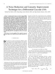
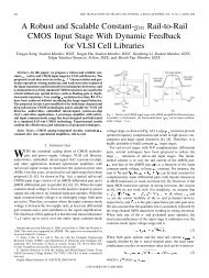
To clarify how much the feedback between <strong>stage</strong>s improves the<br />
bandwidth <strong>of</strong> a 4-<strong>stage</strong> CMA, consider two 2-<strong>stage</strong> CMAs in<br />
cascade form (see Figure 4). It can be intuitively seen that<br />
cascade combination <strong>of</strong> two 2-<strong>stage</strong> CMAs has a bandwidth less<br />
than the single 2-<strong>stage</strong> CMA. Also Figure 5 shows the Matlab<br />
plots <strong>of</strong> the magnitude <strong>of</strong> transfer functions <strong>of</strong> a 4-<strong>stage</strong> CMA<br />
and two cascaded 2-<strong>stage</strong> CMAs for different Gs and F=1.<br />
Indeed, a 4-<strong>stage</strong> CMA has one extra feedback path from the<br />
output <strong>of</strong> the third <strong>stage</strong> to the second <strong>stage</strong>. For G>2.3 in two<br />
cascaded 2-<strong>stage</strong> CMAs, there is a peak (>1.5 dB). The<br />
maximum bandwidth in two cascaded 2-<strong>stage</strong> CMAs is 1.96ω p<br />
that is about 71% <strong>of</strong> the bandwidth <strong>of</strong> one 2-<strong>stage</strong> CMA. Not<br />
only did not the maximum achievable bandwidth <strong>of</strong> 4-<strong>stage</strong><br />
CMA decrease, but also it can reach up to 2.9ω p without<br />
incurring a significant peak in transfer function. In this case the<br />
maximum bandwidth is 6.7 times <strong>of</strong> the bandwidth <strong>of</strong> a 4-<strong>stage</strong><br />
conventional MA.<br />
Increasing G<br />
AC Response<br />
have high loop gains due to passive feedback, which limits the<br />
expansion <strong>of</strong> the bandwidth.<br />
The ratio <strong>of</strong> GBP T <strong>of</strong> CMA and conventional MA shows how<br />
much GBP T is decreased. Unfortunately, GBP T <strong>of</strong> CMA in<br />
comparison with that <strong>of</strong> the conventional MA is decreased (as n<br />
and DC loop gain are increased this ratio decreases further).<br />
However, GBP T <strong>of</strong> CMA in comparison with that <strong>of</strong> other<br />
structures (such as Figure 1) is much better. A simulation <strong>of</strong> the<br />
ratio <strong>of</strong> GBP T <strong>of</strong> an n-<strong>stage</strong> CMA and an n-<strong>stage</strong> conventional<br />
MA with passive feedback for n=2, 4, 6 and 8 for different DC<br />
gain loops is shown in Figure 7. As it shows, increasing DC loop<br />
gain increases CMA’s GBP T . As n is increased, this ratio also<br />
increases. Another parameter is the ratio <strong>of</strong> GBP 1 <strong>of</strong> CMA and a<br />
similar conventional MA that shows how much the GBP 1 is<br />
improved. This ratio is simulated in Figure 8. It shows that GBP 1<br />
<strong>of</strong> an n-<strong>stage</strong> CMA can be several times <strong>of</strong> GBP 1 <strong>of</strong> an n-<strong>stage</strong><br />
conventional MA and the structure shown in Figure 1.<br />
<strong>Bandwidth</strong><br />
ω -3dB=2.91ω p<br />
G=6.1<br />
ω -3dB=1.96ω p<br />
G=2.3<br />
Cascaded two 2-<strong>stage</strong> CMAs -----<br />
4-<strong>stage</strong> CMA<br />
<strong>Bandwidth</strong>(×ωp)<br />
8-Stage x<br />
6-Stage o<br />
4-Stage *<br />
2-Stage +<br />
Frequency/ω p<br />
Figure 5. Matlab plot <strong>of</strong> magnitude <strong>of</strong> transfer functions<br />
<strong>of</strong> schemes in Figure 4 for different Gs and F=1.<br />
The transfer function <strong>of</strong> the CMA for n=6 and 8 can also be<br />
written as a product <strong>of</strong> 2nd-order transfer functions. Figure 6<br />
shows the bandwidth <strong>of</strong> n-<strong>stage</strong> CMA extracted from the<br />
magnitude response simulation result for different DC loop gains<br />
(GF) for n=2, 4, 6, and 8. The n-<strong>stage</strong> CMA for odd ns has a real<br />
pole (@ ω p ) which limits the expansion <strong>of</strong> bandwidth to some<br />
extent. Figure 6 shows that the CMA has two advantages. First,<br />
its bandwidth can be several times <strong>of</strong> ω p (the bandwidth <strong>of</strong> one<br />
<strong>stage</strong>); whereas for n-<strong>stage</strong> conventional MA, ω bw is always less<br />
than ω p . Second, CMA can have more bandwidth as n increases.<br />
As shown above, 4-<strong>stage</strong> CMA has more bandwidth than 2-<strong>stage</strong><br />
CMA. On the contrary, 4-<strong>stage</strong> conventional MA has less<br />
bandwidth than 2-<strong>stage</strong> conventional MA. The maximum<br />
bandwidth that can be obtained for n=8 is 4.51ω p . As F<br />
decreases, a higher G is needed to have the same bandwidth.<br />
Although as n increases CMA can have more bandwidth, it also<br />
needs more GF. Figure 6 shows that if GF is constant, smaller n<br />
gives more bandwidth.<br />
To evaluate the performance <strong>of</strong> a wideband MA topology,<br />
several parameters can be calculated. One <strong>of</strong> them is the<br />
bandwidth <strong>of</strong> MA. It can be proven that for the same number <strong>of</strong><br />
<strong>stage</strong>s and the same GF, both structures <strong>of</strong> CMA and Figure 1<br />
have almost the same bandwidth and comparable group delay<br />
variation. In contrast to CMA, the topology in Figure 1 cannot<br />
dB<br />
DC Loop Gain (G×F)<br />
Figure 6. Matlab plot <strong>of</strong> the bandwidth <strong>of</strong> 2, 4, 6 and 8-<br />
<strong>stage</strong> CMA in ω p for different DC loop gains (GF)<br />
⎛<br />
GBP<br />
⎞<br />
⎜<br />
T <strong>of</strong> CMA<br />
20log<br />
⎝ GBPT<br />
<strong>of</strong> Conventional MAwith PassiveFeedBack⎠<br />
DC Loop Gain (G×F)<br />
8-Stage x<br />
6-Stage o<br />
4-Stage *<br />
2-Stage +<br />
Figure 7. Matlab plot <strong>of</strong> the ratio <strong>of</strong> GBP T <strong>of</strong> n-<strong>stage</strong> CMA<br />
and conventional MA with passive feedback for n=2, 4, 6 and<br />
8.
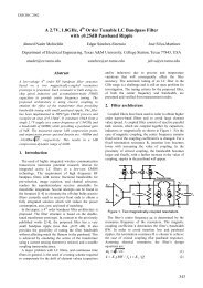
3. TOPOLOGY VALIDATION<br />
The proposed topology was validated through simulation an 8-<br />
<strong>stage</strong> CMA in 0.35µm CMOS. A simple circuit was used as<br />
forward and feedback <strong>stage</strong>s to be easily modeled as Equations<br />
(1) and (8). CMA was combined with a buffer to drive 50Ω in<br />
series with 1pF capacitor at 3V single power supply. The circuit<br />
<strong>of</strong> two <strong>stage</strong>s <strong>of</strong> CMA is shown in Figure 9. To increase the gain<br />
<strong>of</strong> forward and feedback <strong>stage</strong>s, R l =1.8kΩ was chosen, where M l<br />
was used for gain boosting. The M f and M g paired transistors<br />
(feedback and forward transistors, respectively) are matched, so<br />
the Miller effect <strong>of</strong> C gd is partially canceled. Because <strong>of</strong> low-DCgain<br />
<strong>stage</strong> (