Series IP8000/8100 Electro-Pneumatic Positioner - SMC
Series IP8000/8100 Electro-Pneumatic Positioner - SMC
Series IP8000/8100 Electro-Pneumatic Positioner - SMC

Create successful ePaper yourself
Turn your PDF publications into a flip-book with our unique Google optimized e-Paper software.
CAT.ES60-18 A -UK<br />
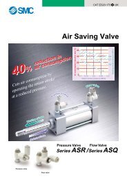
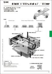
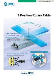
<strong>Electro</strong>-<strong>Pneumatic</strong> <strong>Positioner</strong><br />
Vibration resistance : No resonances<br />
5 to 200Hz<br />
Dust resistance : Conforms to<br />
IEC 60529 IP65<br />
EXH.AIR<br />
A centralized exhaust<br />
system employs the<br />
combination of the check<br />
valve and the labyrinth<br />
effect enhancing both dust<br />
resistance and water<br />
resistance performance.<br />
<strong>Series</strong> <strong>IP8000</strong>/<strong>8100</strong><br />
(Lever type)<br />
(Rotary type)<br />
Fork lever joints (Rotary type)<br />
Can absorb off-centering.<br />
100mm in height (shor<br />
(shortened by y 13%<br />
compared with IP6100)<br />
100mm<br />
Spring pin<br />
Actuator main shaft<br />
Pressure gauge (O. D. ø43)<br />
Enlarged O.D.<br />
allows improved<br />
visibility.<br />
External scale plate (Rotary type)<br />
Improved visibility of<br />
opening indicator<br />
A span adjuster achieves 1/2 split range<br />
Opening current transmission (4 to 20mA DC)<br />
Can detect remote position, rotary type only.<br />
Mounting dimensions are same as conventional<br />
types, series IP6000/6100.<br />
With terminal box<br />
No terminal box also<br />
option also available
MPa<br />
MPa<br />
OUT2<br />
ELECTORO PNEUMATIC <strong>IP8000</strong><br />
MPa<br />
MPa<br />
OUT2<br />
ELECTORO PNEUMATIC <strong>IP8000</strong><br />
<strong>Electro</strong>-<strong>Pneumatic</strong> <strong>Positioner</strong><br />
<strong>Series</strong> <strong>IP8000</strong>/<strong>8100</strong><br />
How to Order<br />
Type<br />
000<br />
100<br />
IP8 000 0 0 0<br />
Lever type feedback<br />
Rotary type<br />
Pressure gauge<br />
0<br />
1<br />
2<br />
3<br />
Specifications<br />
None<br />
0.2MPa<br />
0.3MPa<br />
1.0MPa<br />
Construction<br />
0<br />
No terminal box<br />
POSITIONER<br />
1<br />
With terminal box<br />
POSITIONER<br />
Accessories Note 1)<br />
-<br />
A Note 2)<br />
B Note 2)<br />
C<br />
D<br />
E Note 3)<br />
F Note 3)<br />
G Note 4)<br />
H<br />
J Note 5)<br />
JR<br />
Q<br />
CE marked compliant product<br />
None (Standard)<br />
ø0.7 Output restriction with pilot valve<br />
ø1.0 Output restriction with pilot valve<br />
Fork lever joint M<br />
Fork lever joint S<br />
For stroke 35 to 100mm with lever unit<br />
For stroke 50 to 140mm with lever unit<br />
Compensation spring (A)<br />
With external scale plate<br />
With opening current transmission<br />
(4 to 20mA DC) Clockwise operation<br />
With opening current transmission<br />
(4 to 20mA DC) Counterclockwise operation<br />
<strong>IP8000</strong> has standard lever for stroke (10 to 85mm)<br />
Accessory for <strong>IP8000</strong>, <strong>8100</strong><br />
small capacity actuator<br />
Accessory for IP<strong>8100</strong><br />
Accessory for <strong>IP8000</strong><br />
For <strong>IP8000</strong>, <strong>8100</strong><br />
Accessory for IP<strong>8100</strong><br />
Option for IP<strong>8100</strong> Note 6)<br />
Note 1) If two or more accessories are required, the part numbers should be made according to alphabetical order. (ex. <strong>IP8000</strong>-011-AG)<br />
Note 2) “A” is applied to approx 90cm 3 -capacity actuator. “B” is applied to approx 180cm 3 -capacity actuator.<br />
Note 3) Standard lever is not attached.<br />
Note 4) It is to be used together with “A” or “B” when tending to overshoot by the use of “A” or “B”.<br />
It is mounted to the body as a replacement of the standard compensation spring.<br />
Note 5) Available only with terminal box. Select “1” for the construction.<br />
Note 6) Clockwise operation: The feedback shaft viewed from the positioner cover side moves clockwise in condition that the input signal<br />
and opening current transmission are increased.<br />
Counterclockwise operation: The feedback shaft moves counterclockwise in the above condition.<br />
Item<br />
Type<br />
Input current<br />
Input resistance<br />
Supply air pressure<br />
Standard stroke<br />
Sensitivity<br />
Linearity<br />
Hysteresis<br />
Repeatability<br />
Coefficient of temperature<br />
Supply pressure fluctuation<br />
Output flow<br />
Air consumption<br />
Ambient and fluid<br />
temperature<br />
Air port<br />
Electrical connection<br />
Lever type lever feedback Rotary type cam feedback<br />
Single action Double action Single action Double action<br />
4 to 20mADC Note 1)<br />
235±15Ω (4 to 20mADC)<br />
0.14 to 0.7MPa<br />
10 to 85mm (Deflection angle 10 to 30°) 60 to 100° Note 2)<br />
Within 0.1%F.S.<br />
Within ±1%F.S.<br />
<strong>IP8000</strong><br />
Within 0.5%F.S.<br />
Within ±2%F.S.<br />
Within 0.75%F.S.<br />
Within 1%F.S.<br />
Within 0.5%F.S.<br />
Within 0.1%F.S. / °C<br />
Within 0.3%F.S./0.01MPa<br />
80l/min (ANR) or more (SUP = 0.14MPa)<br />
200l/min (ANR) or more (SUP = 0.4MPa)<br />
5l/min (ANR) or less (SUP = 0.14MPa)<br />
11l/min (ANR) or less (SUP = 0.4MPa)<br />
–20 to 80°C<br />
Rc 1/4 female<br />
G 1/2 female<br />
IP<strong>8100</strong><br />
Wiring method<br />
Resin G 1/2 connector (option)<br />
Exterior covering enclosure JISF8007, IP65 (conforms to IEC Pub.529)<br />
Material<br />
Aluminum diecast body / epoxy resin<br />
Weight<br />
With terminal box 2.6kg (None 2.4kg)<br />
Note 1) 1/2 Split range (Standard)<br />
Note 2) Stroke adjustment: 0 to 60°, 0 to 100°<br />
1
M<br />
A<br />
OU<br />
<strong>Electro</strong>-<strong>Pneumatic</strong> <strong>Positioner</strong><br />
<strong>Series</strong> <strong>IP8000</strong> / <strong>8100</strong><br />
Accessory / Option<br />
Pilot valve with output restriction (<strong>IP8000</strong>, <strong>8100</strong> type)<br />
In general, mounting on a small-size actuator may cause hunting. For<br />
prevention, a pilot valve with a built-in output restriction is available.<br />
The restriction is removable.<br />
Actuator Capacity Orifice size Part number<br />
90cm 3<br />
180cm 3<br />
ø0.7<br />
ø1<br />
P36801080<br />
P36801081<br />
Fork lever joints (IP<strong>8100</strong> type)<br />
Pilot unit part number<br />
P565010-18<br />
P565010-19<br />
Two types of the fork lever joints are available dependent upon<br />
different mounting dimensions.<br />
This is recommended because it can absorb off-centering, compared<br />
with direct mounting type.<br />
Part name<br />
Fork lever assembly M<br />
Fork lever assembly S<br />
M8<br />
63<br />
(S type: 39)<br />
L1=101<br />
(S type: 77)<br />
Part number<br />
P368010-24<br />
P368010-25<br />
M8<br />
L2=31<br />
(M type: 55)<br />
39<br />
(M type: 63)<br />
Actuator main shaft<br />
External feedback lever (<strong>IP8000</strong> type)<br />
Different feedback levers are available dependent upon valve<br />
strokes. Consult with <strong>SMC</strong> in case of 10mm or less stroke.<br />
Stroke<br />
10 to 85mm (Accessory “Nil”)<br />
35 to 100mm (Accessory “E”)<br />
50 to 140mm (Accessory “F”)<br />
Resin connector<br />
Unit number<br />
P368010-20<br />
P368010-21<br />
P368010-22<br />
Size M<br />
125<br />
110<br />
110<br />
Optional cable connectors are available for different cable sizes.<br />
Cable connector (option)<br />
Part name<br />
Resin-made cable clamp unit (A)<br />
Resin-made cable clamp unit (B)<br />
6.1<br />
N<br />
16<br />
M 5<br />
Part number<br />
P368010-26<br />
P368010-27<br />
Size N<br />
150<br />
195<br />
275<br />
Suited cable outer diameter<br />
ø7 to ø9<br />
ø9 to ø11<br />
Actuator main shaft<br />
Side mounting with the fork<br />
lever assembly M<br />
Bottom mounting with the fork<br />
lever assembly S<br />
Cable connector G1/2<br />
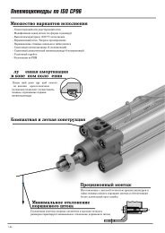
Exploded View<br />
(3) Cover seal<br />
POSITIONER<br />
ELECTORO PNEUMATIC <strong>IP8000</strong><br />
Body cover unit<br />
(1) Pilot valve unit<br />
Compensation spring<br />
Zero adjusting unit<br />
Feedback spring<br />
Mini-terminal unit (No terminal box)<br />
Span adjusting unit<br />
SPAN<br />
Torque motor unit<br />
Feedback shaft assembly<br />
Terminal joint unit<br />
(No terminal box)<br />
<strong>SMC</strong><br />
MPa<br />
Feedback<br />
lever unit<br />
<strong>SMC</strong><br />
MPa<br />
SUP<br />
Body unit<br />
Terminal box unit<br />
(2) Base seal<br />
Replacement Parts<br />
No. Description<br />
1 Pilot valve unit<br />
2<br />
Base seal<br />
3 Cover seal<br />
Part no.<br />
P565010-7<br />
P56501012-3<br />
P56501013<br />
Note<br />
<strong>IP8000</strong>/<strong>8100</strong><br />
2
<strong>Series</strong> <strong>IP8000</strong>/<strong>8100</strong><br />
Piping<br />
<strong>IP8000</strong> / Lever type<br />
Positive operation<br />
When the input signal is increased, the stem<br />
moves as allow mark.<br />
SUP<br />
OUT1<br />
<br />
Single action<br />
When the input signal is increased, the stem<br />
moves as allow mark.<br />
(Positive valve operation by its reverse<br />
operation mode)<br />
<br />
SUP<br />
OUT2<br />
Double action<br />
When the input signal is increased, the<br />
cylinder rod moves as allow mark.<br />
SUP<br />
OUT1<br />
OUT2<br />
IN -<br />
+<br />
Span adjusting lever<br />
normal position<br />
IN -<br />
+<br />
Span adjusting lever<br />
normal position<br />
IN -<br />
+<br />
Span adjusting lever<br />
normal position<br />
Reverse operation<br />
When the input signal is increased, the stem<br />
moves as allow mark.<br />
(Reverse valve operation by its positive<br />
operation mode) OUT2<br />
IN -<br />
+<br />
<br />
SUP<br />
OUT2 is plugged.<br />
Span adjusting lever<br />
reverse position<br />
When the input signal is increased, the stem<br />
moves as allow mark.<br />
IN -<br />
+<br />
SUP<br />
OUT1 is plugged.<br />
OUT1<br />
<br />
Span adjusting lever<br />
reverse position<br />
When the input signal is increased, the<br />
cylinder rod moves as allow mark.<br />
IN -<br />
+<br />
SUP<br />
OUT1<br />
OUT2<br />
Span adjusting lever<br />
reverse position<br />
OUT1 is plugged.<br />
OUT2 is plugged.<br />
IP<strong>8100</strong> / Rotary type<br />
Positive operation<br />
Reverse operation<br />
3<br />
When the input signal is increased, the<br />
actuator shaft rotates in a clockwise direction.<br />
Single action<br />
When the input signal is increased, the<br />
actuator shaft rotates in a clockwise direction.<br />
(Positive valve operation by its reverse<br />
operation<br />
mode)<br />
When the input signal is increased, the actuator When the input signal is increased, the actuator<br />
shaft rotates in a counter clockwise direction. shaft rotates in a counter clockwise direction.<br />
(Reverse valve operation by its positive<br />
operation<br />
mode)<br />
IN -<br />
+<br />
IN -<br />
+<br />
Main shaft<br />
OUT1<br />
SUP<br />
Main shaft<br />
OUT2<br />
<br />
SUP<br />
<br />
OUT2 is plugged.<br />
OUT1 is plugged.<br />
Single action actuator<br />
The cam of the<br />
positioner<br />
should be set on<br />
the DA surface.<br />
Single action actuator<br />
The cam of the<br />
positioner<br />
should be set on<br />
the RA surface.<br />
IN -<br />
+<br />
IN -<br />
+<br />
Main shaft<br />
<br />
SUP<br />
Main shaft<br />
SUP<br />
OUT2<br />
OUT1 is plugged.<br />
OUT1<br />
<br />
OUT2 is plugged.<br />
Single action actuator<br />
The cam of the<br />
positioner<br />
should be set on<br />
the DA surface.<br />
Single action actuator<br />
The cam of the<br />
positioner<br />
should be set on<br />
the RA surface.<br />
Double action<br />
When the input signal is increased, the<br />
actuator shaft rotates in a clockwise direction.<br />
IN -<br />
+<br />
When the input signal is increased, the actuator<br />
shaft rotates in a counter clockwise direction.<br />
IN -<br />
+<br />
Main shaft<br />
OUT1<br />
SUP<br />
Main shaft<br />
OUT2<br />
SUP<br />
Double action actuator<br />
OUT2<br />
Double action actuator<br />
OUT1<br />
The cam of the<br />
positioner<br />
should be set on<br />
the DA surface.<br />
The cam of the<br />
positioner<br />
should be set on<br />
the RA surface.
<strong>Electro</strong>-<strong>Pneumatic</strong> <strong>Positioner</strong><br />
<strong>Series</strong> <strong>IP8000</strong> / <strong>8100</strong><br />
Installation<br />
<strong>IP8000</strong> type (Lever type lever feedback)<br />
1 The unit should be mounted using bolts firmly fixed through<br />
mounting holes on the side or back of the positioner.<br />
Mounting examples<br />
<strong>Positioner</strong><br />
Bracket<br />
<strong>Positioner</strong><br />
Bracket<br />
<strong>Positioner</strong><br />
Bracket<br />
Bracket<br />
Direct mounting to diaphragm<br />
With L-type bracket<br />
With front bracket<br />
2 A connecting fitting or pin to transfer the displacement of valve<br />
stem should be mounted at a position so that the feedback<br />
lever is at right angles to the valve stem for an input current of<br />
50%. The right figure is the configuration viewed from the front.<br />
Backlash eliminating spring<br />
Right angle<br />
Input current<br />
Input current<br />
(Or 100%)<br />
0% position<br />
50% position<br />
Input current 100% position<br />
(Or 0%)<br />
Feedback lever<br />
Connecting fitting<br />
<strong>Positioner</strong> body Valve stem<br />
IP<strong>8100</strong> type (Rotary type cam feedback)<br />
1 The positioner should be mounted so that the feedback shaft<br />
is aligned with the shaft of the rotary actuator.<br />
Mounting bracket<br />
conforming to DIN IEC 534<br />
<strong>Positioner</strong> <strong>IP8000</strong> mounted using a bracket conforming<br />
to DIN IEC 534<br />
Part number: INI-224-0-56-1<br />
No.<br />
1<br />
2<br />
3<br />
4<br />
5<br />
6<br />
7<br />
8<br />
9<br />
Qty.<br />
1<br />
2<br />
4<br />
4<br />
2<br />
4<br />
2<br />
1<br />
2<br />
Description<br />
Pilot valve unit<br />
Bolt<br />
Bolt<br />
Nut<br />
Washer<br />
Spring washer<br />
Bracket<br />
Rod<br />
Nut<br />
Note<br />
INI-224-0-56<br />
M8x16 DIN933-Zn5bkcB<br />
M8x20 DIN933-Zn5bkcB<br />
M8 DIN934-Zn5bkcB<br />
B8, 4 DIN125-Zn5bkcB<br />
B8 DIN127-Zn5bkcB<br />
100 320-4480<br />
M6x70<br />
M6<br />
OUT1<br />
OUT2<br />
OUT1<br />
OUT2<br />
Bracket<br />
Installation using the thread<br />
on the side of positioner<br />
Installation using the thread<br />
on the back of positioner<br />
4
<strong>Series</strong> <strong>IP8000</strong>/<strong>8100</strong><br />
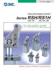
Principle of Operation<br />
<strong>IP8000</strong> / Lever type<br />
When the input current increases, (11) the plate spring of (12) the torque motor<br />
will work as a pivot, (13) armature will receive a counter clockwise torque, (4)<br />
the counter weight will be pushed to the left, the clearance between (6) the<br />
nozzle and (5) the flapper will increase, and the nozzle back pressure will<br />
decrease. Consequently, (7) the exhaust valve of (1) the pilot valve moves to<br />
the right, the output pressure of OUT1 increases and (15) the diaphragm<br />
moves downwards. The motion of (15) the diaphragm acts on (10) the<br />
feedback spring through (8) the feedback lever, (14) the transmission lever<br />
and (9) the span adjustment lever to rest at the balance position generated by<br />
the input current. (2) The compensation spring is for direct feedback of the<br />
motion of (7) the exhaust valve to (4) the counter weight to increase the<br />
stability of the loop. The zero point should be adjusted by change of (3) the<br />
zero adjustment spring tention.<br />
Single action positive operation<br />
(1) Pilot valve<br />
Supply valve B<br />
(4) Counter weight<br />
(2) Compensation spring<br />
(3) Zero adjusting spring<br />
Zero adjusting screw<br />
Stopper screw<br />
(Do not move)<br />
X View<br />
SUP OUT2 OUT1<br />
EXH.<br />
X<br />
Diaphragm<br />
(5) Flapper<br />
(6) Nozzle<br />
M<br />
A<br />
Automatic / Manual<br />
change-over screw<br />
(Built-in bleed<br />
restriction)<br />
Sensitivity adjusting screw<br />
(Adjusts GAIN)<br />
Supply valve A<br />
(8) Feedback lever<br />
(9) Span adjusting lever<br />
(7) Exhaust<br />
valve<br />
Span adjusting<br />
lever shaft<br />
Transmission pin<br />
Lock screw<br />
(14) Transmission lever<br />
(15) Diaphragm valve<br />
For reverse position, exchange<br />
the shaft of the span adjusting<br />
lever to the opposite side. The<br />
span adjusting screw faces<br />
upward in this condition.<br />
(See “Piping”)<br />
E<br />
(10) Feedback spring<br />
(11) Plate spring<br />
Span adjusting screw<br />
(12) Torque motor<br />
Input current terminal<br />
(13) Armature<br />
Block diagram<br />
SUP<br />
IN<br />
Current<br />
Zero adjusting<br />
spring<br />
Torque motor<br />
+<br />
-<br />
+<br />
-<br />
Restriction ) (<br />
Nozzle<br />
flapper<br />
Diaphragm<br />
Exhaust valve<br />
Supply valve<br />
Diaphragm<br />
valve<br />
Stem<br />
stroke<br />
OUT<br />
Compensatory<br />
spring<br />
Feedback<br />
spring<br />
Span adjusting<br />
lever<br />
Feedback<br />
lever<br />
5
<strong>Electro</strong>-<strong>Pneumatic</strong> <strong>Positioner</strong><br />
<strong>Series</strong> <strong>IP8000</strong> / <strong>8100</strong><br />
IP<strong>8100</strong> / Rotary type<br />
When the input current increases, (12) the plate spring of (13) the torque motor will<br />
work as a pivot, (14) armature will receive a counter-clockwise torque, (4) the<br />
counter weight will be pushed to the left and the clearance between (6) the nozzle<br />
and (5) the flapper will increase, and the nozzle back pressure will decrease.<br />
Consequently, (7) the exhaust valve of (1) the pilot valve moves to the right, the<br />
output pressure of OUT1 increases that of OUT2 decreases and (16) the rotary<br />
actuator moves. The motion of (16) the actuator acts on (10) the feedback spring<br />
through (11) the feedback shaft, (8) the cam, (9) the span adjustment lever and<br />
(15) transmission lever to rest at the balance position generated by the input<br />
current. (8) the cam is set on the DA surface and operates positively while (16) the<br />
oscillating actuator shaft rotates in a clockwise direction when the input signal is<br />
increased. (2) The compensation spring is for direct feedback of the motion of (7)<br />
the exhaust valve to (4) the counter weight to increase the stability of the loop. The<br />
zero point should be adjusted by change of (3) the zero adjustment spring tension.<br />
Double action positive operation<br />
X View<br />
M<br />
A<br />
Stopper screw<br />
(Do not move)<br />
Automatic / Manual change-over screw<br />
(Built-in bleed restriction)<br />
(1) Pilot valve<br />
Supply valve B<br />
(4) Counter weight<br />
(2) Compensation spring<br />
(3) Zero adjusting spring<br />
Zero adjusting screw<br />
SUP OUT2 OUT1<br />
EXH.<br />
X<br />
Diaphragm<br />
(5) Flapper<br />
(6) Nozzle<br />
Sensitivity adjusting screw<br />
(Adjusts GAIN)<br />
Supply valve A<br />
(7) Exhaust<br />
valve<br />
(9) Span adjusting lever<br />
Pairing<br />
(8) Cam<br />
For reverse position, set<br />
by turning over the cam<br />
and reversing connections<br />
of outlets OUT1 and OUT2.<br />
(15) Transmission lever<br />
(10) Feedback spring<br />
E<br />
(11) Feedback shaft<br />
(12) Plate spring<br />
(13) Torque motor<br />
(16) Oscillating<br />
actuator<br />
Input current terminal<br />
(14) Armature<br />
Fork joint<br />
Block diagram<br />
SUP<br />
IN<br />
Current<br />
Zero adjusting<br />
spring<br />
Torque motor<br />
+<br />
-<br />
+<br />
-<br />
Restriction ) (<br />
Nozzle<br />
flapper<br />
Diaphragm<br />
Exhaust valve<br />
Supply valve<br />
Oscillating<br />
actuator<br />
Angle of<br />
rotation<br />
OUT<br />
Compensatory<br />
spring<br />
Feedback<br />
spring<br />
Span adjusting<br />
lever<br />
Cam<br />
Feedback<br />
shaft<br />
6
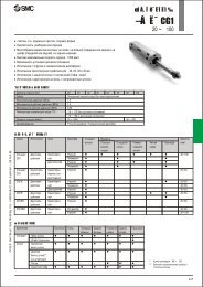
<strong>Series</strong> <strong>IP8000</strong>/<strong>8100</strong><br />
Dimensions / <strong>IP8000</strong> (Lever type)<br />
<strong>IP8000</strong>-00 (No terminal box)<br />
View A<br />
2<br />
30<br />
46<br />
40<br />
35<br />
192<br />
110<br />
58<br />
23.5<br />
23.5<br />
43<br />
198<br />
14<br />
2 x M8 depth12<br />
(Female thread<br />
for side mounting)<br />
38<br />
OUT1.Rc1/4<br />
SUP.Rc1/4<br />
122<br />
65<br />
22.5<br />
100<br />
4 x M8 depth12<br />
(Female thread for rear mounting)<br />
117<br />
147<br />
With optional resin cable clamp<br />
Applicable cable O. D. ø7 to 9:P368010-26<br />
Applicable cable O. D. ø9 to 11:P368010-27<br />
9<br />
39<br />
38<br />
MPa<br />
MPa<br />
OUT2.Rc1/4<br />
With plug<br />
OUT2<br />
POSITIONER<br />
ELECTORO PNEUMATIC <strong>IP8000</strong><br />
125<br />
194<br />
110<br />
42<br />
20<br />
50<br />
6.1<br />
16<br />
125<br />
At accessory “E”: 110<br />
{ }<br />
At accessory “F”: 110<br />
150<br />
At accessory “E”: 195<br />
{ }<br />
At accessory “F”: 275<br />
A<br />
5<br />
39 11<br />
35<br />
1<br />
E<br />
G1/2<br />
Electric conduit<br />
<strong>IP8000</strong>-01 (With terminal box)<br />
Electric conduit 2 x G1/2<br />
E<br />
100<br />
MPa<br />
OUT2.Rc1/4<br />
With plug<br />
MPa<br />
OUT2<br />
POSITIONER<br />
ELECTORO PNEUMATIC <strong>IP8000</strong><br />
At accessory “E”: 110<br />
{ }<br />
At accessory “F”: 110 5<br />
150<br />
125<br />
At accessory “E”: 195<br />
12 168 { At accessory “F”: 275 }<br />
8<br />
110<br />
38<br />
60<br />
2<br />
30<br />
40<br />
35<br />
View A<br />
192<br />
110<br />
58<br />
23.5<br />
23.5<br />
43<br />
218<br />
14<br />
2 x M8 depth12<br />
(Female thread<br />
for side mounting)<br />
38<br />
OUT1.Rc1/4<br />
SUP.Rc1/4<br />
122<br />
65<br />
22.5<br />
4 x M8 depth12<br />
(Female thread for rear mounting)<br />
162<br />
117<br />
9<br />
39<br />
42<br />
20<br />
50<br />
6.1<br />
16<br />
125<br />
39 11<br />
A<br />
7
50%<br />
50%<br />
<strong>Electro</strong>-<strong>Pneumatic</strong> <strong>Positioner</strong><br />
<strong>Series</strong> <strong>IP8000</strong> / <strong>8100</strong><br />
Dimensions / IP<strong>8100</strong> (Rotary type)<br />
IP<strong>8100</strong>-00 (No terminal box)<br />
100<br />
42<br />
40<br />
35<br />
192<br />
110<br />
58<br />
23.5<br />
9<br />
23.5<br />
43<br />
231<br />
198<br />
OUT2<br />
15<br />
44<br />
46<br />
39 11<br />
38<br />
OUT1.Rc1/4<br />
SUP.Rc1/4<br />
MPa<br />
122<br />
65<br />
50<br />
20<br />
22.5<br />
147<br />
117<br />
39<br />
MPa<br />
POSITIONER<br />
ELECTORO PNEUMATIC IP<strong>8100</strong><br />
0%<br />
25%<br />
DA<br />
75%<br />
A<br />
1<br />
E<br />
View A 4 x M8 depth12<br />
Female for rear mounting<br />
2 x M8 depth12<br />
Female for side mounting<br />
With optional resin cable clamp<br />
Applicable cable O. D. ø7 to 9:P368010-26<br />
Applicable cable O. D. ø9 to 11:P368010-27<br />
38<br />
OUT2.Rc1/4<br />
125<br />
194<br />
110<br />
100%<br />
35<br />
At accessory “H”:<br />
(with external scale plate)<br />
G1/2<br />
Electric conduit<br />
IP<strong>8100</strong>-01 (With terminal box)<br />
2 x G1/2<br />
Electric<br />
conduit<br />
E<br />
100<br />
15<br />
60<br />
44<br />
46<br />
40<br />
35<br />
192<br />
110<br />
58<br />
23.5<br />
23.5<br />
43<br />
251<br />
218<br />
38<br />
OUT1.Rc1/4<br />
SUP.Rc1/4<br />
122<br />
65<br />
50 42<br />
20<br />
22.5<br />
162<br />
117<br />
9<br />
39<br />
MPa<br />
MPa<br />
OUT2<br />
POSITIONER<br />
ELECTORO PNEUMATIC IP<strong>8100</strong><br />
0%<br />
25%<br />
DA<br />
75%<br />
39 11<br />
A<br />
100%<br />
View A<br />
2 x M8 depth12 4 x M8 depth12<br />
Female thread for side mounting Female thread for rear mounting<br />
OUT2.Rc1/4<br />
125<br />
12 168<br />
110<br />
At accessory “H”:<br />
(with external scale plate)<br />
8<br />
38<br />
8
<strong>Series</strong> <strong>IP8000</strong>/<strong>8100</strong><br />
Safety Instructions<br />
These safety instructions are intended to prevent a hazardous situation and/or<br />
equipment damage. These instructions indicate the level of potential hazard by a<br />
label of "Caution", "Warning" or "Danger". To ensure safety, be sure to observe<br />
ISO 4414 Note 1), JIS B 8370 Note 2) and other safety practices.<br />
Caution : Operator error could result in injury or equipment damage.<br />
Warning : Operator error could result in serious injury or loss of life.<br />
Danger : In extreme conditions, there is a possible result of serious injury or loss of life.<br />
Note 1) ISO 4414: <strong>Pneumatic</strong> fluid power -- General rules relating to systems<br />
Note 2) JIS B 8370: <strong>Pneumatic</strong> system axiom<br />
Warning<br />
1. The compatibility of pneumatic equipment is the responsibility of the person<br />
who designs the pneumatic system or decides its specifications.<br />
Since the products specified here are used in various operating conditions, their compatibility with the<br />
specific pneumatic system must be based on specifications or after analysis and/or tests to meet your<br />
specific requirements. The expected performance and safety assurance will be the responsibility of the<br />
person who has determined the compatibility of the system. This person should continuously review the<br />
suitability of all items specified, referring to the latest catalogue information with a view to giving due<br />
consideration to any possibility of equipment failure when configuring a system.<br />
2. Only trained personnel should operate pneumatically operated machinery and<br />
equipment.<br />
Compressed air can be dangerous if handled incorrectly. Assembly, handling or maintenance of<br />
pneumatic systems should be performed by trained and experienced operators.<br />
3. Do not service machinery/equipment or attempt to remove components until<br />
safety is confirmed.<br />
1. Inspection and maintenance of machinery/equipment should only be performed once measures to<br />
prevent falling or runaway of the driven object have been confirmed.<br />
2. When equipment is to be removed, confirm the safety process as mentioned above. Cut the supply<br />
pressure for this equipment and exhaust all residual compressed air in the system.<br />
3. Before machinery/equipment is restarted, take measures to prevent shooting-out of cylinder piston<br />
rod, etc. (Bleed air into the system gradually to create back pressure.)<br />
4. Contact <strong>SMC</strong> if the product is to be used in any of the following conditions:<br />
1. Conditions and environments beyond the given specifications, or if product is used outdoors.<br />
2. Installation on equipment in conjunction with atomic energy, railway, air navigation, vehicles, medical<br />
equipment, food and beverages, recreation equipment, emergency stop circuits, clutch and brake<br />
circuit in press applications, or safety equipment.<br />
3. An application which has the possibility of having negative effects on people, property, or animals,<br />
requiring special safety analysis.<br />
9
<strong>Series</strong> <strong>IP8000</strong>/<strong>8100</strong><br />
<strong>Electro</strong>-<strong>Pneumatic</strong> <strong>Positioner</strong> Precautions<br />
Be sure to read before handling.<br />
Warning<br />
Operation<br />
1. Do not operate the positioner outside the specified range as this may cause<br />
problems. (Refer to the specifications.)<br />
2. Design the system to include a safety circuit to avoid the risk of danger<br />
should the positioner suffer failure.<br />
3. Covers for the terminal and body should be in place while operating.<br />
Caution<br />
Caution<br />
Caution<br />
Handling<br />
1. Avoid impact to the positioner body or torque motor and any excessive<br />
force to the armature, as these actions may cause damage to the product.<br />
Handle carefully while transporting and operating.<br />
2. When exposed to possible moisture invasion, please take the necessary<br />
measures. For example, if the positioner is left on-site for long periods, a<br />
plug should be put in the piping port and an external cover fitted to avoid<br />
water penetration.<br />
Take measures to avoid dew condensation inside the positioner if<br />
exposed to high temperature and humidity. Take enough measures<br />
against condensation especially when packing for export.<br />
3. Keep magnetic field off the positioner, as this affects its characteristics.<br />
Air Supply<br />
1. Use only dehumidified and dust-extracted clean compressed clean air as<br />
the positioner contains extra-fine orifices such as restrictor and nozzle.<br />
Do not use a lubricator.<br />
2. Do not use compressed air containing chemicals, organic solvents, salinity<br />
or corrosive gases, as this may cause malfunction.<br />
3. Use dehumidified and dust-extracted clean compressed air as an air supply.<br />
4. When operating below the freezing point, protect the positioner from<br />
freezing.<br />
5. Piping<br />
Before piping make sure to clean away all chips, cutting oil, dust etc.<br />
When installing piping or fitting into a port, ensure that sealant<br />
material does not enter the port inside.<br />
When using seal tape, leave 1.5 to 2 threads exposed on the end of<br />
the pipe/fitting.<br />
6. Lubrication<br />
The positioner has a fixed orifice and nozzle, which contain fine<br />
paths in them. Use filtered, dehydratedair and avoid the use of<br />
lubricators as this may cause malfunction of the positioner. Ensure<br />
that the airsupply system is filtered to 5 micron.<br />
Operating Environment<br />
1. Do not use in an environment where the product is directly exposed to<br />
corrosive gases, chemicals, saltwater, water or steam.<br />
2. Do not mount the product in a location where it will be subject to strong<br />
vibrations and/or shock.<br />
3. Do not mount the product in a location where it is exposed to radiant heat.<br />
4. Allow sufficient space for maintenance and adjustment around the product<br />
when mounted.<br />
Warning<br />
Caution<br />
Maintenance<br />
1. After installation, repair or disassembly, connect compressed air and<br />
conduct tests to confirm appropriate function and leakage.<br />
Do not use the positioner when noise from the bleeder sounds louder<br />
compared with the initial state, or when it does not operate normally. If<br />
these occur, check immediately if assembled and mounted correctly.<br />
Never modify electrical construction.<br />
1. Confirm whether the compressed air is clean.<br />
Dust, oil, or moisture mixed within the equipment may result in<br />
malfunction and positioner problems. Perform periodic<br />
inspection of the air preparation equipment to ensure clean air is<br />
always supplied.<br />
2. Improper handling of compressed air is dangerous. Not only observing the<br />
product specifications, but also replacement of elements and other<br />
maintenance activities should be performed by personnel having sufficient<br />
knowledge and experience pertaining to instrumentation equipment.<br />
3. Perform annual inspections of the positioner.<br />
Replace badly damaged seals and units such as diaphragm and<br />
O-ring during the inspection.<br />
When used in tough environmental and/or service conditions<br />
such as seaside locations, replacements should be undertaken<br />
more frequently.<br />
4. When performing inspections, demounting the positioner, or replacing the<br />
elements with the positioner still in its mounted position, first, stop the<br />
compressed air, then exhaust the residual pressure before undertaking<br />
operation.<br />
5. Should the restrictor become clogged with carbon particles, etc., demount<br />
automatic/manual change-over screw (with built-in restrictor) and clean it<br />
using a ø0.2 wire.<br />
Stop the compressed air and remove the screw to switch the<br />
pilot valve off before replacing the restrictor.<br />
6. Apply just a small amount of grease to sliding parts (O-ring and exhaust<br />
valve) when disassemble a pilot valve.<br />
Use silicone grease, for example, SH45 produced by Du Pond-<br />
Toray Co., Ltd.<br />
7. Confirm air leakage from compressed air piping and junctions.<br />
Air leakage from air piping results in reduced operational<br />
performance and a decline of characteristics, etc.<br />
It is structurally necessary for air to be released from the<br />
bleeder, it is not abnormal as long as the air consumption is<br />
within the specified range.<br />
Installation<br />
Warning<br />
1. Do not install unless the safety instructions have been read and<br />
understood.<br />
2. Since zero-point varies depending on the mounting position, the<br />
zero point should be adjusted after installation.<br />
3. Avoid hitting the product with metallic objects!<br />
4. Avoid using this product in non-explosive environments which<br />
can become explosive due to air leakage!<br />
10
© DiskArt 1988<br />
EUROPEAN SUBSIDIARIES:<br />
Austria<br />
<strong>SMC</strong> Pneumatik GmbH (Austria).<br />
Girakstrasse 8, A-2100 Korneuburg<br />
Phone: +43 2262-62280, Fax: +43 2262-62285<br />
E-mail: office@smc.at<br />
http://www.smc.at<br />
France<br />
<strong>SMC</strong> Pneumatique, S.A.<br />
1, Boulevard de Strasbourg, Parc Gustave Eiffel<br />
Bussy Saint Georges F-77607 Marne La Vallee Cedex 3<br />
Phone: +33 (0)1-6476 1000, Fax: +33 (0)1-6476 1010<br />
E-mail: contact@smc-france.fr<br />
http://www.smc-france.fr<br />
Netherlands<br />
<strong>SMC</strong> <strong>Pneumatic</strong>s BV<br />
De Ruyterkade 120, NL-1011 AB Amsterdam<br />
Phone: +31 (0)20-5318888, Fax: +31 (0)20-5318880<br />
E-mail: info@smcpneumatics.nl<br />
http://www.smcpneumatics.nl<br />
Spain<br />
<strong>SMC</strong> España, S.A.<br />
Zuazobidea 14, 01015 Vitoria<br />
Phone: +34 945-184 100, Fax: +34 945-184 124<br />
E-mail: post@smc.smces.es<br />
http://www.smces.es<br />
Belgium<br />
<strong>SMC</strong> <strong>Pneumatic</strong>s N.V./S.A.<br />
Nijverheidsstraat 20, B-2160 Wommelgem<br />
Phone: +32 (0)3-355-1464, Fax: +32 (0)3-355-1466<br />
E-mail: post@smcpneumatics.be<br />
http://www.smcpneumatics.be<br />
Germany<br />
<strong>SMC</strong> Pneumatik GmbH<br />
Boschring 13-15, D-63329 Egelsbach<br />
Phone: +49 (0)6103-4020, Fax: +49 (0)6103-402139<br />
E-mail: info@smc-pneumatik.de<br />
http://www.smc-pneumatik.de<br />
Norway<br />
<strong>SMC</strong> <strong>Pneumatic</strong>s Norway A/S<br />
Vollsveien 13 C, Granfos Næringspark N-1366 Lysaker<br />
Tel: +47 67 12 90 20, Fax: +47 67 12 90 21<br />
E-mail: post@smc-norge.no<br />
http://www.smc-norge.no<br />
Sweden<br />
<strong>SMC</strong> <strong>Pneumatic</strong>s Sweden AB<br />
Ekhagsvägen 29-31, S-141 71 Huddinge<br />
Phone: +46 (0)8-603 12 00, Fax: +46 (0)8-603 12 90<br />
E-mail: post@smcpneumatics.se<br />
http://www.smc.nu<br />
Bulgaria<br />
<strong>SMC</strong> Industrial Automation Bulgaria EOOD<br />
16 kliment Ohridski Blvd., fl.13 BG-1756 Sofia<br />
Phone:+359 2 9744492, Fax:+359 2 9744519<br />
E-mail: office@smc.bg<br />
http://www.smc.bg<br />
Greece<br />
S. Parianopoulus S.A.<br />
7, Konstantinoupoleos Street, GR-11855 Athens<br />
Phone: +30 (0)1-3426076, Fax: +30 (0)1-3455578<br />
E-mail: parianos@hol.gr<br />
http://www.smceu.com<br />
Poland<br />
<strong>SMC</strong> Industrial Automation Polska Sp.z.o.o.<br />
ul. Konstruktorska 11A, PL-02-673 Warszawa,<br />
Phone: +48 22 548 5085, Fax: +48 22 548 5087<br />
E-mail: office@smc.pl<br />
http://www.smc.pl<br />
Switzerland<br />
<strong>SMC</strong> Pneumatik AG<br />
Dorfstrasse 7, CH-8484 Weisslingen<br />
Phone: +41 (0)52-396-3131, Fax: +41 (0)52-396-3191<br />
E-mail: info@smc.ch<br />
http://www.smc.ch<br />
Croatia<br />
<strong>SMC</strong> Industrijska automatika d.o.o.<br />
Crnomerec 12, 10000 ZAGREB<br />
Phone: +385 1 377 66 74, Fax: +385 1 377 66 74<br />
E-mail: office@smc.hr<br />
http://www.smceu.com<br />
Hungary<br />
<strong>SMC</strong> Hungary Ipari Automatizálási Kft.<br />
Budafoki ut 107-113, H-1117 Budapest<br />
Phone: +36 1 371 1343, Fax: +36 1 371 1344<br />
E-mail: office@smc-automation.hu<br />
http://www.smc-automation.hu<br />
Portugal<br />
<strong>SMC</strong> Sucursal Portugal, S.A.<br />
Rua de Engº Ferreira Dias 452, 4100-246 Porto<br />
Phone: +351 22-610-89-22, Fax: +351 22-610-89-36<br />
E-mail: postpt@smc.smces.es<br />
http://www.smces.es<br />
Turkey<br />
Entek Pnömatik San. ve Tic Ltd. Sti.<br />
Perpa Tic. Merkezi Kat: 11 No: 1625, TR-80270 Okmeydani Istanbul<br />
Phone: +90 (0)212-221-1512, Fax: +90 (0)212-221-1519<br />
E-mail: smc-entek@entek.com.tr<br />
http://www.entek.com.tr<br />
Czech Republic<br />
<strong>SMC</strong> Industrial Automation CZ s.r.o.<br />
Hudcova 78a, CZ-61200 Brno<br />
Phone: +420 5 414 24611, Fax: +420 5 412 18034<br />
E-mail: office@smc.cz<br />
http://www.smc.cz<br />
Ireland<br />
<strong>SMC</strong> <strong>Pneumatic</strong>s (Ireland) Ltd.<br />
2002 Citywest Business Campus, Naas Road, Saggart, Co. Dublin<br />
Phone: +353 (0)1-403 9000, Fax: +353 (0)1-464-0500<br />
E-mail: sales@smcpneumatics.ie<br />
http://www.smcpneumatics.ie<br />
Romania<br />
<strong>SMC</strong> Romania srl<br />
Str Frunzei 29, Sector 2, Bucharest<br />
Phone: +40 213205111, Fax: +40 213261489<br />
E-mail: smcromania@smcromania.ro<br />
http://www.smcromania.ro<br />
© DiskArt<br />
UK<br />
<strong>SMC</strong> <strong>Pneumatic</strong>s (UK) Ltd<br />
Vincent Avenue, Crownhill, Milton Keynes, MK8 0AN<br />
Phone: +44 (0)800 1382930 Fax: +44 (0)1908-555064<br />
E-mail: sales@smcpneumatics.co.uk<br />
http://www.smcpneumatics.co.uk<br />
Denmark<br />
<strong>SMC</strong> Pneumatik A/S<br />
Knudsminde 4B, DK-8300 Odder<br />
Phone: +45 70252900, Fax: +45 70252901<br />
E-mail: smc@smc-pneumatik.dk<br />
http://www.smcdk.com<br />
Italy<br />
<strong>SMC</strong> Italia S.p.A<br />
Via Garibaldi 62, I-20061Carugate, (Milano)<br />
Phone: +39 (0)2-92711, Fax: +39 (0)2-9271365<br />
E-mail: mailbox@smcitalia.it<br />
http://www.smcitalia.it<br />
Russia<br />
<strong>SMC</strong> Pneumatik LLC.<br />
36/40 Sredny pr. St. Petersburg 199004<br />
Phone.:+812 118 5445, Fax:+812 118 5449<br />
E-mail: smcfa@peterlink.ru<br />
http://www.smc-pneumatik.ru<br />
Estonia<br />
<strong>SMC</strong> <strong>Pneumatic</strong>s Estonia OÜ<br />
Laki 12-101, 106 21 Tallinn<br />
Phone: +372 (0)6 593540, Fax: +372 (0)6 593541<br />
E-mail: smc@smcpneumatics.ee<br />
http://www.smcpneumatics.ee<br />
Latvia<br />
<strong>SMC</strong> <strong>Pneumatic</strong>s Latvia SIA<br />
Smerla 1-705, Riga LV-1006, Latvia<br />
Phone: +371 (0)777-94-74, Fax: +371 (0)777-94-75<br />
E-mail: info@smclv.lv<br />
http://www.smclv.lv<br />
Slovakia<br />
<strong>SMC</strong> Priemyselná Automatizáciá, s.r.o.<br />
Námestie Martina Benku 10, SK-81107 Bratislava<br />
Phone: +421 2 444 56725, Fax: +421 2 444 56028<br />
E-mail: office@smc.sk<br />
http://www.smc.sk<br />
Finland<br />
<strong>SMC</strong> <strong>Pneumatic</strong>s Finland OY<br />
PL72, Tiistinniityntie 4, SF-02031 ESPOO<br />
Phone: +358 207 513513, Fax: +358 207 513595<br />
E-mail: smcfi@smc.fi<br />
http://www.smc.fi<br />
Lithuania<br />
UAB Ottensten Lietuva<br />
Savanoriu pr. 180, LT-2600 Vilnius, Lithuania<br />
Phone/Fax: +370-2651602<br />
Slovenia<br />
<strong>SMC</strong> industrijska Avtomatika d.o.o.<br />
Grajski trg 15, SLO-8360 Zuzemberk<br />
Phone: +386 738 85240 Fax: +386 738 85249<br />
E-mail: office@smc-ind-avtom.si<br />
http://www.smc-ind-avtom.si<br />
OTHER SUBSIDIARIES WORLDWIDE:<br />
ARGENTINA, AUSTRALIA, BOLIVIA, BRASIL, CANADA, CHILE,<br />
CHINA, HONG KONG, INDIA, INDONESIA, MALAYSIA, MEXICO,<br />
NEW ZEALAND, PHILIPPINES, SINGAPORE, SOUTH KOREA,<br />
TAIWAN, THAILAND, USA, VENEZUELA<br />
http://www.smceu.com<br />
http://www.smcworld.com<br />
<strong>SMC</strong> CORPORATION 1-16-4 Shimbashi, Minato-ku, Tokio 105 JAPAN; Phone:03-3502-2740 Fax:03-3508-2480<br />
Produced and printed by <strong>SMC</strong> European Marketing Centre 3/05<br />
Specifications are subject to change without prior notice<br />
and any obligation on the part of the manufacturer.