( US Army Strategic Communications Command ... - Survival Books
( US Army Strategic Communications Command ... - Survival Books
( US Army Strategic Communications Command ... - Survival Books

Create successful ePaper yourself
Turn your PDF publications into a flip-book with our unique Google optimized e-Paper software.
WWW.SURVIVALEBOOKS.COM<br />
FM 11-23<br />
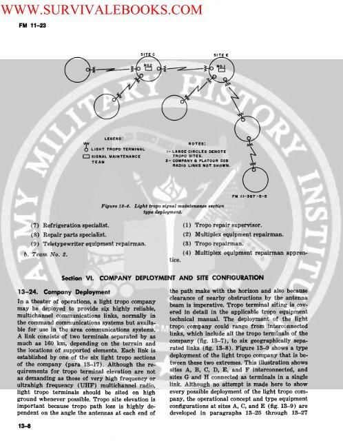
SITE C<br />
SITE E<br />
LEGEND:<br />
LIGHT TROPO TERMINALE<br />
r ok<br />
CIRCLES<br />
E SIGNAL MAINTENANCE TROPO SITES.<br />
TEAM<br />
2-COMPANY a PLATOON SS\<br />
RADIO LINKS NOT SHOWN.<br />
-<br />
~NOTES:<br />
Figure 18-6. Light tropo signal maintenance section<br />
type deployment.<br />
FM 11-367-5-5<br />
(7) Refrigeration specialist. (1) Tropo repair supervisor.<br />
(8) Repair parts specialist. (2) Multiplex equipment repairman.<br />
(9) Teletypewriter equipment repairman. (3) Tropo repairman.<br />
b. Team No. 2. (4) Multiplex equipment repairman apprentice.<br />
Section VI.<br />
COMPANY DEPLOYMENT AND SITE CONFIGURATION<br />
13-24. Company Deployment the path make with the horizon and also because<br />
clearance of nearby obstructions<br />
In<br />
by<br />
a theater of operations,<br />
the antenna<br />
a light tropo company<br />
may be deployed to provide si. highly reliable,<br />
beam is imperative. Tropo terminal siting is cov-<br />
multichannel communications links, normally technical manual. The deployment of the light<br />
the command communications systems but availa-company<br />
could range from interconnected<br />
ble for use in the area communications systems.<br />
tropo company could range from interconnected<br />
A link consists of two terminals separated by as links, which include all the tropo terminals of the<br />
much as 160 km, depending on the terrain and company (fig. 13-7), to six geographically sepathe<br />
locations of supported elements. Each link is rated links (fig. 13-8). Figure 13-9 shows a type<br />
established by one of the six light tropo sections deployment of the light tropo company that is beof<br />
the company (para 13-17). Although the re- tween these two extremes. This illustration shows<br />
quirements for tropo terminal elevation are not sites A, B, C, D, E, and F interconnected, and<br />
as demanding as those of very high frequency or sites G and H connected as terminals in a single<br />
ultrahigh frequency (UHF) multichannel radio, link. Although no attempt is made here to show<br />
light tropo terminals should be sited on high every possible deployment of the light tropo comground<br />
whenever possible. Tropo site elevation is pany, the operational concept and type equipment<br />
important because tropo path loss is highly de- configurations at sites A, C, and E (fig. 13-9) are<br />
pendent on the angle the antennas at each end of developed in paragraphs 13-25 through 13-27<br />
13-8