P89LPC935 Microcontroller Tutorial - gmitWEB
P89LPC935 Microcontroller Tutorial - gmitWEB
P89LPC935 Microcontroller Tutorial - gmitWEB

You also want an ePaper? Increase the reach of your titles
YUMPU automatically turns print PDFs into web optimized ePapers that Google loves.
<strong>P89LPC935</strong> <strong>Microcontroller</strong> <strong>Tutorial</strong><br />
Agenda<br />
• Basic Architecture of the <strong>P89LPC935</strong> microcontroller<br />
– Memory, Input/Output Ports, Clocking, Timers<br />
• Writing C code for 8051 based microcontrollers<br />
– C51 language extensions<br />
• Sample Diploma Project<br />
– The Keyless lock<br />
Diploma Project <strong>Tutorial</strong> 1
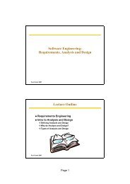
MCB900 Board<br />
Diploma Project <strong>Tutorial</strong> 2
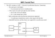
MCB900 Features<br />
• RS232 driver provides a standard COM port interface.<br />
• 8 buffered LEDs display I/O port 2 status information.<br />
• Potentiometer and Jumper for ADC1 channel 2 analog input.<br />
• 3.3V low-drop regulator allows wide power supply range (5V-9VDC).<br />
• Jumpers for flexible ISP and debug configurations.<br />
• All <strong>P89LPC935</strong>/P89LPC932 pins available on flexible connection area.<br />
• Prototyping area: 55mm x 25mm (2.1" x 1.0").<br />
Diploma Project <strong>Tutorial</strong> 3
<strong>P89LPC935</strong> <strong>Microcontroller</strong> Basic Architecture<br />
• 8-bit microcontroller<br />
• 8 KByte Flash Program memory<br />
• 256 Byte Data Memory (RAM) + 512 bytes auxiliary RAM (XDATA)<br />
• 512 Byte EEPROM<br />
• 3V device but I/O pins are 5V tolerant<br />
• Up to 26 input/output pins (4 ports P0 to P3)<br />
• 2 16-bit timer/counters<br />
• UART for serial interfacing<br />
• 15 interrupt sources, 5 priority levels<br />
• 2 clock machine cycle<br />
– All instructions execute in 1, 2 or 4 machine cycles<br />
– Instructions execute 6 times faster than 8051<br />
• Program and data memory may not be expanded externally<br />
Diploma Project <strong>Tutorial</strong> 4
<strong>P89LPC935</strong> <strong>Microcontroller</strong> Advanced Architecture<br />
• In-System Programmable (ISP)<br />
• In-Application Programmable (IAP)<br />
• Watchdog timer<br />
• Real Time Clock<br />
• On-chip power-on reset<br />
• I2C port<br />
• SPI port<br />
• Dual 4-input multiplexed 8-bit ADCs<br />
• Dual DAC<br />
• 2 Analog Comparators<br />
Diploma Project <strong>Tutorial</strong> 5
<strong>P89LPC935</strong> <strong>Microcontroller</strong> Advanced Architecture<br />
Diploma Project <strong>Tutorial</strong> 6
Memory Organisation<br />
• The 8051 architecture supports 2 parallel memory spaces<br />
– Program memory used for code and constant storage<br />
– Data memory used for variable storage<br />
Diploma Project <strong>Tutorial</strong> 7
Memory Organisation<br />
• Data Memory<br />
– 256 bytes of on-chip data RAM<br />
• Used for stack, registers, bit addressable memory and variables<br />
• Upper 128 bytes is indirectly addressable only<br />
– SFRs (Special Function Registers)<br />
• Used for control and status<br />
– 512 bytes of on-chip auxiliary data RAM<br />
• Duplicates 8051 off-chip data memory<br />
• Slower access than directly accessible memory<br />
– 512 bytes data EEPROM<br />
• Non-volatile data memory<br />
• Accessed by SFR only<br />
• Program Memory<br />
– 8KByte flash memory<br />
– Used for application code and optionally for user data<br />
– ISP serial loader stored here<br />
Diploma Project <strong>Tutorial</strong> 8
Input/Output Ports<br />
• <strong>P89LPC935</strong> is a 28 pin device<br />
• Up to 26 of the pins are available for input/Output<br />
– 3 8-bit ports P0, P1, P2<br />
• Port pins are labeled Px.0 to Px.7 where x is the port number<br />
• P1.5 is input only and is unavailable if using an external reset<br />
• P1.2 and P1.3 may be configured as open-drain or input only<br />
– 2-bit port P3<br />
• P3 is unavailable if using an external crystal<br />
Diploma Project <strong>Tutorial</strong> 9
Input/Output Ports<br />
Diploma Project <strong>Tutorial</strong> 10
Input/Output Ports<br />
• <strong>P89LPC935</strong> is a 3V device but the pins are 5V tolerant<br />
– Can interface directly to 5V TTL devices<br />
– Connecting a pin directly to 5V will increase power consumption<br />
– Each input can sink up to 20mA but the limit for the IC is 100mA<br />
– Configuration of the port pins may be changed to suit the hardware<br />
interface by writing to the Port Mode SFR registers.<br />
Diploma Project <strong>Tutorial</strong> 11
Port Configurations<br />
• Input Only<br />
– This is the default configuration at reset<br />
• Quasi-bidirectional<br />
– Standard 80C51 outputs<br />
– Strong pull-down can sink 20mA when output = ‘0’<br />
– Weak pull-up can source 20uA when output = ‘1’<br />
– Can be used to interface to TTL devices<br />
• Push-Pull<br />
– Used when more source current is required<br />
• Can source 3.2mA when outputting a ‘1’<br />
– Strong pull-down can sink 20mA when output = ‘0’<br />
• Open Drain<br />
– Needs an external pull-up to output a logic ‘1’<br />
– Best solution when interfacing to 5V circuits<br />
Diploma Project <strong>Tutorial</strong> 12
Input/Output Port Configuration<br />
• On reset all port pins default to input<br />
• To change a port configuration the Port Output Mode Registers 1 & 2 must be<br />
written to.<br />
• A port may contain a mix of input and output pins.<br />
– e.g. configure P0.0 to P0.2 as input, all other Port 0 pins as quasibidirectional<br />
– P0M1 = 00000111 (0x07)<br />
– P0M2 = 00000000 (0x00)<br />
Diploma Project <strong>Tutorial</strong> 13
Interfacing Inputs to 5V Logic<br />
• Although the supply voltage is lower, the I/O-pins are 5V-tolerant.<br />
– i.e., the I/O stages cannot actively drive the outputs higher than the<br />
supply voltage, but they may be pulled to 5V externally.<br />
• The LPC935 inputs can be driven directly from the outputs of 5V logic<br />
families.<br />
• For a 3.3V power supply, the worst case Schmitt trigger input switching<br />
levels are V IL<br />
= 0.726V and V IH<br />
= 2.31V.<br />
Diploma Project <strong>Tutorial</strong> 14
Interfacing Outputs to 5V Logic<br />
• LPC935 output can drive a TTL input.<br />
• The output high level voltage (VOH) is not high enough to drive a CMOS<br />
input.<br />
• When outputting a 0, the LPC935 port pin can sink up to 20mA – total limit<br />
for the chip is 100mA. Bigger loads require external interface circuitry.<br />
Diploma Project <strong>Tutorial</strong> 15
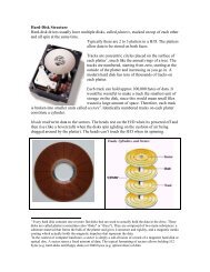
Hardware Interfacing<br />
3.3V<br />
5V<br />
3.3V<br />
3.3V<br />
VDD<br />
VDD<br />
micro P0.1<br />
P0.1<br />
micro<br />
VSS<br />
VSS<br />
Direct hardware interface<br />
20mA max sink current<br />
Configure as quasi-bidir or<br />
Push-pull<br />
Interfacing to 5V hardware<br />
Configure as open-drain<br />
5V supply drives load<br />
Diploma Project <strong>Tutorial</strong> 16
89LPC935 Clock<br />
• A machine cycle is the minimum amount of time in which any P89LP935<br />
operation can execute<br />
– A machine cycle is 2 clock periods in duration<br />
– All instructions will execute in 1, 2 or 4 machine cycles<br />
– The internal timers operate every machine cycle if enabled<br />
• 3 clock source options<br />
– External crystal up to 12MHz<br />
– Internal RC 7.373MHz oscillator<br />
• Used on MCB900 board<br />
• Allows 2 XTAL pins to be used for input/output<br />
– Internal watchdog oscillator (400KHz)<br />
Use 33pF capacitor<br />
for 12MHz crystal<br />
Diploma Project <strong>Tutorial</strong> 17
Clock Configuration<br />
Diploma Project <strong>Tutorial</strong> 18
Keil C51 Cross Compiler<br />
• ANSI C Compiler<br />
– Generates fast compact code for the 8051 and it’s derivatives<br />
• Advantages of C over Assembler<br />
– Do not need to know the microcontroller instruction set<br />
– Register allocation and addressing modes are handled by the compiler<br />
– Programming time is reduced<br />
– Code may be ported easily to other microcontrollers<br />
• C51 supports a number of C language extensions that have been added to<br />
support the 8051 microcontroller architecture e.g.<br />
– Data types<br />
– Memory types<br />
– Pointers<br />
– Interrupts<br />
Diploma Project <strong>Tutorial</strong> 19
C51 Data Types<br />
Data Type Bits Range<br />
bit 1 0,1<br />
unsigned char 8 0 to 255<br />
signed char 8 -128 to +127<br />
unsigned int 16 0 to 65535<br />
signed int 16 -32768 to +32767<br />
unsigned long 32 0 to 4294967296<br />
signed long 32 -2147483648 to + 2147483647<br />
sbit 1 0,1<br />
Diploma Project <strong>Tutorial</strong> 20
C51 Memory Types<br />
• Memory type extensions allow access to all 8051 memory types.<br />
– A variable may be assigned to a specific memory space<br />
• code<br />
– Program memory.<br />
– unsigned char code const1 = 0x55; //define a constant<br />
– char code string1[] = “hello”; //define a string<br />
• data<br />
– Lower 128 bytes of internal data memory<br />
– unsigned int data x; //16-bit variable x<br />
• idata<br />
– All 256 bytes if internal data memory<br />
• bdata<br />
– Bit addressable area of internal data memory<br />
• xdata<br />
– External data memory (512 bytes of on-chip auxiliary data RAM)<br />
Diploma Project <strong>Tutorial</strong> 21
Example Code (1)<br />
//program to add 2 8-bit variables<br />
void main()<br />
{<br />
unsigned char data num1, num2, result;<br />
}<br />
num1 = 10;<br />
num2 = 25;<br />
result = num1 + num2;<br />
• This code will use 3 bytes of internal data memory (00 to 7FH)<br />
• What happens if the result exceeds 255?<br />
Diploma Project <strong>Tutorial</strong> 22
Example Code (2)<br />
//program to add 2 8-bit variables<br />
//a flag should be set if the result exceeds 100<br />
void main()<br />
{<br />
unsigned char data num1, num2;<br />
unsigned int data result;<br />
bit overflow;<br />
}<br />
num1 = 10;<br />
num2 = 25;<br />
result = num1 + num2;<br />
if (result >100)<br />
overflow = 1;<br />
Diploma Project <strong>Tutorial</strong> 23
Accessing Port Pins<br />
• The microcontroller port should be configured at the start of the program.<br />
//configure port 2 to be quasi bi-directional<br />
P2M1 = 0x00;<br />
P2M2 = 0x00; //all 8 pins are quasi bi-directional<br />
• Writing to an entire port<br />
P2 = 0x12;<br />
//Port 2 = 12H (00010010 binary)<br />
P2 &= 0xF0; //clear lower 4 bits of Port 2<br />
P2 |= 0x03; //set P2.0 and P2.1<br />
• Reading from a port<br />
unsigned char data status;<br />
status = P1; //read from Port 1<br />
Diploma Project <strong>Tutorial</strong> 24
Example Code (3)<br />
//Program to read from 8 switches connected to Port 1. The status of the switches<br />
//is written to 8 LEDs connected to Port 2.<br />
#include //SFR address definitions<br />
void main()<br />
{<br />
unsigned char data status; //variable to hold switch status<br />
P1M1 = 0xFF;<br />
P1M2 = 0;<br />
//port 1 is input<br />
P2M1 = 0;<br />
P2M2 = 0xFF;<br />
//port 2 is output<br />
}<br />
//continuous loop to read switches and display the status<br />
while(1)<br />
{<br />
status = P1;<br />
P2 = status;<br />
}<br />
Diploma Project <strong>Tutorial</strong> 25
Accessing Individual Port Pins<br />
• Writing to a port pin<br />
//write a logic 1 to port 0 pin 1<br />
P0^1 = 1;<br />
• In a program using lots of individual port pins it is better coding practice to<br />
name the pins according to their function<br />
sbit power_led = P0^1;<br />
power_led = 1;<br />
• Reading from a port pin<br />
//Turn on LED if switch is active<br />
sbit switch_input = P2^0;<br />
if (switch_input)<br />
else<br />
power_led = 1;<br />
power_led = 0;<br />
Diploma Project <strong>Tutorial</strong> 26
Example Code (4)<br />
//program to flash an LED connected to Port 2 pin 0 every second<br />
#include <br />
sbit LED = P2^0;<br />
void delay();<br />
void main()<br />
{<br />
P2M1 = 0;<br />
P2M2 = 0;<br />
while (1)<br />
{<br />
LED = 0; //LED off<br />
delay();<br />
LED = 1; //LED on<br />
delay();<br />
}<br />
}<br />
//Delay function<br />
void delay()<br />
{<br />
…….<br />
}<br />
Diploma Project <strong>Tutorial</strong> 27
Generating Delays (1)<br />
• Use a for loop<br />
– Does not use any timer resources<br />
– Uses CPU resources while running<br />
• i.e. no other task can be performed during delay loop<br />
– Can result in large amounts of machine code being generated<br />
– Results may be different for different compilers<br />
• The following code results in a half second delay for the <strong>P89LPC935</strong><br />
operating off the 7.373MHz RC oscillator<br />
void delay()<br />
{<br />
unsigned int i;<br />
for (i=0; i < 50000; i++);<br />
}<br />
Diploma Project <strong>Tutorial</strong> 28
Generating Delays (2)<br />
• Use assembly code<br />
– Use DJNZ loops to produce very compact code<br />
– Does not use timer resources<br />
– Uses CPU resources while running<br />
• i.e. no other task can be performed during delay loop<br />
• Use timer 0 or timer 1<br />
– Very efficient mechanism of producing accurate delays<br />
– Timer mode, control and counter registers must be configured<br />
– Timer run bit is used to start/stop the timer<br />
– The timer flag can be polled to determine when required time delay has<br />
elapsed<br />
Diploma Project <strong>Tutorial</strong> 29
Generating Delays (3)<br />
• When enabled the timer counts from an initial value to FFFFH and then<br />
overflows to 0000H. The count is incremented every 2 clocks.<br />
• Delay = 2 x (2 16 – initial value)/fosc<br />
• Max. delay for a 7.373MHz crystal is 2 17 /7373000 = 17.118msec.<br />
• Calculate the initial value for a delay of 10msec<br />
– initial value = [2 16 – (0.01 x 7373000)]/2<br />
– Initial value = 28671 = 6FFFH<br />
– Load TL0 with FFH<br />
– Load TH0 with 6FH<br />
Diploma Project <strong>Tutorial</strong> 30
Using Timer 0 to Generate a Delay<br />
//function to generate a delay of x times 10msec<br />
void delay(unsigned char x)<br />
{<br />
unsigned char z;<br />
TR0 = 0;<br />
//stop timer<br />
TF0 = 0;<br />
//clear timer flag<br />
TMOD = 0x01;<br />
//mode 1 - 16 bit timer<br />
TAMOD = 0;<br />
for (z=0;z
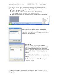
Connecting the MCB900 to your project circuit<br />
• Your project circuit board will most likely be powered from 5V.<br />
• The MCB900 board uses an on-board 3.3V supply. This is generated by<br />
regulating an external voltage source.<br />
– You can power the MCB900 using the supplied 6V mains regulator or<br />
using a power supply connected to the VIN terminals (next to the serial<br />
port connector).<br />
• Your project board must share the same ground as the MCB900 board.<br />
– Connect a wire from the MCB900 VSS terminal to the ground rail of your<br />
project board.<br />
• You may regulate the VIN power rail of the MCB900 to generate a 5V power<br />
rail for your project board (use a 7805 regulator).<br />
MCB VIN<br />
VIN<br />
GND<br />
VOUT<br />
+<br />
10uF<br />
100nF<br />
5V<br />
MCB VSS<br />
Diploma Project <strong>Tutorial</strong> 32
Example Project<br />
• Keyless Doorlock<br />
– The door is opened by a 4 digit password entered via a keypad<br />
– 2 LED’s show the status of the lock<br />
– A solenoid is used to open/close the door latch<br />
Diploma Project <strong>Tutorial</strong> 33