Installation and Operating Instructions GEN-AUTO Energy Division
Installation and Operating Instructions GEN-AUTO Energy Division
Installation and Operating Instructions GEN-AUTO Energy Division

You also want an ePaper? Increase the reach of your titles
YUMPU automatically turns print PDFs into web optimized ePapers that Google loves.
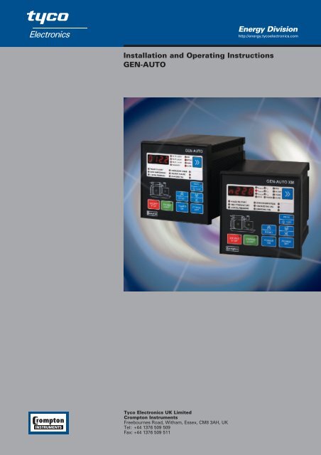
<strong>Energy</strong> <strong>Division</strong><br />
http://energy.tycoelectronics.com<br />
<strong>Installation</strong> <strong>and</strong> <strong>Operating</strong> <strong>Instructions</strong><br />
<strong>GEN</strong>-<strong>AUTO</strong><br />
Tyco Electronics UK Limited<br />
Crompton Instruments<br />
Freebournes Road, Witham, Essex, CM8 3AH, UK<br />
Tel: +44 1376 509 509<br />
Fax: +44 1376 509 511
Contents<br />
Page<br />
Section 1 Introduction 5<br />
Section 2 <strong>Installation</strong> 7<br />
2.1 Unpacking 7<br />
2.2 Unit Configuration 7<br />
2.3 Mechanical <strong>Installation</strong> 7<br />
2.4 Electrical Connections 9<br />
2.4.1 Charge Generator current 17<br />
Section 3 Programming 18<br />
3.1 Procedure 18<br />
3.2 Program functions 21<br />
3.2.1 Alternator Voltage 21<br />
3.2.2 Alternator Frequency 21<br />
3.2.3 Battery voltage lower limit 21<br />
3.2.4 Load current limit (<strong>GEN</strong>-<strong>AUTO</strong>/XM only) 21<br />
3.2.5 Speed sensing input selection 21<br />
3.2.6 Stop/Fuel Solenoid selection 22<br />
3.2.7 Stop magnet energising time 22<br />
3.2.8 Engine started signals 22<br />
3.2.9 Battery Voltage 23<br />
3.2.10 Engine Starting 23<br />
3.2.12 Oil pressure bypass time 23<br />
3.2.13 Control on delay 24<br />
3.2.14 Engine cooling time 24<br />
3.2.15 Spare Inputs 1-2-3 24<br />
3.2.16 Configurable relay outputs 1-2 24<br />
3.2.17 Maintenance Indication 25<br />
3.2.18 Operator passwor 25<br />
3.2.19 Technician Password 25<br />
<strong>GEN</strong><strong>AUTO</strong> MANUAL<br />
Issue 2 01/2004
Contents<br />
Page<br />
Section 4 Commissioning 26<br />
Section 5 Operation 27<br />
5.1 Controls <strong>and</strong> Indicators 27<br />
5.2 Starting the Engine 30<br />
5.3 Stopping the Engine 30<br />
Section 6 Fault Finding 31<br />
6.1 General 31<br />
6.2 Fault indications 31<br />
6.2.1 Low Oil Pressure LED 31<br />
6.2.2 High Temperature LED 31<br />
6.2.3 Start Failure LED 31<br />
6.2.4 Charge generator Failure LED 32<br />
6.2.5 Low/High Speed LED 32<br />
6.2.6 Alternator Voltage Failure LED 32<br />
6.2.7 EStP– Emergency Stop 32<br />
6.2.8 bAT1 - Low Battery Voltage message 32<br />
6.2.9 bAT2 - Weak Battery Alarm message 32<br />
6.2.10 bAEr – Routine Maintenance Due 33<br />
6.2.11 ocr -Over Current Failure message 33<br />
(<strong>GEN</strong>-<strong>AUTO</strong>/XM only)<br />
Section 7 Specification 34<br />
Section 8 PC Interface 36<br />
8.1 Technical Specifications 36<br />
8.2 <strong>Installation</strong> 37<br />
8.2.1 To run the software 38<br />
8.3 Description 38<br />
8.3.1 Observation Window 39<br />
8.3.2 Operator Parameters Window 40<br />
8.3.3 Technician Parameters Window 40<br />
8.4 Main Menu 41<br />
8.4.1 File 41<br />
8.4.2 Programming 41<br />
8.4.3 Settings 42
Contents<br />
Page<br />
8.5 Operation 43<br />
8.5.1 Accessing Operator Parameters Window 43<br />
8.5.2 Accessing Technician Parameters Window 44<br />
8.5.3 Loading a Configuration File From Disc 44<br />
8.5.4 Saving Parameters to a Configuration File 45<br />
8.5.5 Uploading Parameters from the Unit 45<br />
8.5.6 Downloading Parameters to the unit 45<br />
Index 46
Section 1 Introduction<br />
These products provide control <strong>and</strong> protection in the operation of a generator set. The units<br />
allow starting <strong>and</strong> stopping of the engine <strong>and</strong> indicates status <strong>and</strong> fault conditions. The unit<br />
monitors:<br />
●<br />
●<br />
●<br />
●<br />
Engine temperature,<br />
Oil pressure,<br />
Charging Alternator<br />
Alternator output (voltage <strong>and</strong> frequency).<br />
It controls:<br />
●<br />
●<br />
●<br />
●<br />
●<br />
Engine fuel supply or engine stopping, via external solenoid<br />
Starter motor, via external relay.<br />
Alarm horn<br />
Preheating (configurable relay feature)<br />
Load transfer (configurable relay feature)<br />
A four-digit, seven-segment display provides extensive monitoring of unit <strong>and</strong> alternator<br />
parameters, including:<br />
●<br />
●<br />
●<br />
●<br />
●<br />
●<br />
Alternator output voltage <strong>and</strong> frequency<br />
Engine RPM<br />
Battery voltage<br />
Elapsed time<br />
Error indication<br />
Program parameters<br />
The unit is extensively programmable, with password protection on two levels.<br />
In the event that the engine fails to start on the first attempt, the attempt will be repeated a<br />
programmed number of times or until successful.<br />
If a fault is detected, the unit shuts down the engine <strong>and</strong> indicates the failure by flashing an<br />
appropriate fault LED.<br />
Remote fuel, start <strong>and</strong> emergency stop inputs provide for remote control of the engine.<br />
Three user-defined inputs are included that sound an external horn, flash indicators on the panel<br />
<strong>and</strong> can be programmed to stop the engine.<br />
Two extra outputs can be configured to act on an alarm, when the engine is running, when a<br />
load can be transferred to the alternator, or when engine preheating is required.<br />
The operational parameters of the unit can be monitored <strong>and</strong> controlled from a PC via a built-in<br />
RS-232 port.<br />
5
Section 2 <strong>Installation</strong><br />
2.1 Unpacking<br />
Carefully unpack the unit <strong>and</strong> check for damage to the unit or to the cables supplied. Retain the<br />
packing in case of future need, e.g. for returning the unit for calibration.<br />
Check the contents, as follows:<br />
●<br />
●<br />
●<br />
●<br />
One <strong>GEN</strong>-<strong>AUTO</strong><br />
<strong>Operating</strong> Manual<br />
Screw clamp electrical connectors<br />
Panel mounting clamps<br />
Report any shortage or damage to your local sales office as soon as possible.<br />
2.2 Unit Configuration<br />
The unit can be programmed using buttons <strong>and</strong> display on the front panel. Refer to Section 3<br />
Programming for details.<br />
Warning :<br />
The generator can be started remotely via the Remote Start/Stop input if the<br />
Remote Fuel Input is high, irrespective of the position of the Key switch on the<br />
front panel of this unit. When using the remote start feature, the installer<br />
should connect sound <strong>and</strong> light warning devices to meet local safety codes <strong>and</strong><br />
ensure that personnel are warned prior to commencing a remote starting<br />
sequence.<br />
2.3 Mechanical <strong>Installation</strong><br />
The unit is designed for panel mounting. Fixing is by two screw fixings.<br />
1. Remove the fixings from the unit, if fitted, <strong>and</strong> unscrew the screws in the fixings.<br />
2. Insert the unit in the panel cut-out from the front. Maximum panel thickness is 7 mm<br />
(0.28 inch).<br />
3. Insert the fixings in the slots at the diagonal corners of the unit <strong>and</strong> tighten the fixing screws<br />
to secure the unit against the panel. See Figure 2.1.<br />
6
Figure 2.1 Unit fixing<br />
Figure 2.1 Front view <strong>and</strong> Panel cut-out<br />
7
Figure 2.3 Side view<br />
2.4 Electrical Connections<br />
Warning: Beware of the high mains voltages connected to this unit.<br />
Figure 2.4 Rear view<br />
8
Figure 2.5 <strong>GEN</strong>-<strong>AUTO</strong> single phase connections schematic<br />
9
Figure 2.6 <strong>GEN</strong>-<strong>AUTO</strong> three phase connections schematic<br />
10
Table 1 shows the connections <strong>and</strong> recommended cable sizes. Table 2 describes the functions of<br />
the connections.<br />
Table 1 Unit wiring<br />
Pin Description Cable Notes<br />
size<br />
(mm)<br />
1 Output to Start solenoid 2.5 + DC supply from pin 2.<br />
12A maximum.<br />
2 Positive battery supply input 2.5 Supplies external solenoids<br />
3 Output to Fuel solenoid 2.5 + DC supply from pin 2<br />
12A maximum<br />
4 Output to horn 1.0 + DC supply from pin 7 5A maximum<br />
5 Configurable output 2 1.0 5A maximum<br />
6 Configurable output 1 1.0 5A maximum<br />
7 Positive battery supply input 2.5 Supplies unit, horn <strong>and</strong> configurable<br />
outputs.<br />
8 Alternator neutral/negative battery 2.5<br />
supply to unit<br />
9 Alternator neutral/negative battery 2.5<br />
supply to chassis<br />
14 Alternator Neutral 1.0<br />
15 L1 alternator input 1.0<br />
16 L2 alternator input 1.0 3-phase only<br />
17 L3 alternator input 1.0 3-phase only<br />
18 Input from charge generator 1.0 Terminal must be left unconnected if<br />
not used.<br />
19 Input from Low Oil Pressure switch 0.5 Switch to 0V.<br />
20 Input from High Temperature switch. 0.5 Switch to 0V.<br />
21 Input from Remote Start/Stop switch 0.5 Switch to 0V to Start. Open switch to Stop.<br />
22 Emergency stop input 0.5 Normally closed. Open on emergency.<br />
23 Input from Spare switch 1. 0.5 Switch to 0V.<br />
24 Input from Spare switch 2 0.5 Switch to 0V.<br />
25 Input from Spare switch 3. 0.5 Switch to 0V.<br />
26 Input from magnetic pick-up 0.5<br />
27 Input from magnetic pick-up 0.5<br />
11
WARNING:<br />
Remote Starting. Arrangements must be made to prevent remote starting of the<br />
engine while engine maintenance is being carried out. This can be achieved by<br />
using a key switch as the remote double-pole switch, such that the key can be<br />
removed to prevent remote starting.<br />
Table 2 Connection functions<br />
Pin Function<br />
1 Output to Start solenoid. +DC from pin 2. Controls starter motor.<br />
2 Battery positive input. +12 or +24V. Feeds external solenoids<br />
3 Output to Fuel/Stop solenoid. +DC from pin 2. Controls fuel to engine or controls<br />
engine stopping.<br />
4 Output to horn. +DC from pin 7. Alarm output.<br />
5 Configurable output 2 Can be programmed to provide contact closures when: alarm<br />
6 Configurable output 1 occurs, engine is running or load transfer is permitted.<br />
7 Positive battery input. +12V or +24V. Feeds unit, horn <strong>and</strong> configurable outputs.<br />
8 Battery negative / neutral (0V) to the Unit.<br />
9 Battery negative / neutral (0V) connection to chassis.<br />
15 L1<br />
Voltage inputs from alternator. Unit can be programmed to use<br />
16 L2<br />
frequency of alternator output to detect when engine has started.<br />
17 L3<br />
Pins 16 <strong>and</strong> 17 not used on single phase applications.<br />
18 Charge generator excitation current. Is used to detect when engine has started.<br />
See Section 2.4.1 Charge Generator current.<br />
19 Input from Low Oil Pressure switch. Normally closed contact to 0V. Open on low<br />
pressure. Can be used to detect when engine has started.<br />
20 Input from High Temperature switch. Switched to 0V when engine temperature exceeds<br />
thermostat setting.<br />
21 Input from remote Start switch. Normally open contact. Closed to 0V to start engine.<br />
Open switch to stop engine.<br />
22 Input from Emergency Stop switch. Contact normally closed to 0V. Open on emergency<br />
to stop the engine.<br />
23 Spare 1 input. Normally open. When switched to 0V, sounds the horn <strong>and</strong> flashes<br />
indicator on panel. Can be programmed to stop the engine..<br />
24 Spare 2 input. Normally open. When switched to 0V, sounds the horn <strong>and</strong> flashes<br />
indicator on panel. Can be programmed to stop the engine.<br />
25 Spare 3 input. Normally open. When switched to 0V, sounds the horn <strong>and</strong> flashes<br />
indicator on panel. Can be programmed to stop the engine.<br />
26<br />
27<br />
Input from magnetic pickup. Unit can be programmed for number of teeth detected<br />
on wheel. 3-35 V p-p 35-10000 Hz.<br />
14
2.4.1 Charge Generator current<br />
The unit uses the Charge generator current input to detect when the engine is running. The<br />
<strong>GEN</strong>-<strong>AUTO</strong> connection effectively replaces the usual charge indicator lamp. It supplies current to<br />
the rotor coil from the battery until the engine is running, at which time the Charge Generator<br />
powers the rotor via the diode trio. The <strong>GEN</strong>-<strong>AUTO</strong> circuits sense the resultant voltage at pin 18.<br />
This is initially low at near Battery -, as the circuit supplies a high current to the rotor coil, rising<br />
to near Battery + once the engine is running. Figure 2.9 shows the arrangement.<br />
Figure 2.9 Input from Charge generator<br />
17
Section 3 Programming<br />
3.1 Procedure<br />
Many of the unit functions can be set by programming. Programming can be carried out only<br />
while the unit is in Stop mode. Proceed as follows:<br />
1. If the unit is off, press the button to turn it on.<br />
2. Press the button. If the engine is running, it will stop.<br />
3. Press the button <strong>and</strong> hold it, for approximately 10 seconds, until the PROG LED<br />
lights.<br />
4. You may enter either an Operator password or a Technician password. The Operator<br />
password restricts access to the primary programming functions P00-08 <strong>and</strong> P38 only. The<br />
Technician password gives access to all programming functions. If you wish to enter the<br />
Operator password, press . To enter the Technician password, press for<br />
ten seconds <strong>and</strong> then . In both cases, the display shows 0000.<br />
5. Use the <strong>and</strong> keys to increment <strong>and</strong> decrement the display until it shows<br />
the correct password. When the unit is initially supplied, the password for both Operator<br />
<strong>and</strong> Technician is 0000. To prevent unauthorised access, use parameter P37 to change the<br />
Operator password <strong>and</strong> parameter P38 to change the Technician password. The Technician<br />
password is only accessible if you have entered as a technician.<br />
6. Press to confirm your password entry. If the password is incorrect, the unit will<br />
drop out of Program mode. If the password is correct, the display will show the first<br />
programmable parameter – P00. You are now in program mode. If no keys are pressed for a<br />
period of approximately 20 seconds, the unit will return to the normal operating mode.<br />
7. To view or change a parameter, press the key repeatedly until the display shows the<br />
parameter number <strong>and</strong> then press<br />
value of the selected parameter.<br />
to select it. The display will show the current<br />
8. Use the <strong>and</strong> keys to set the displays to the required value.<br />
9. Press to accept the displayed value. The display will show the number of the next<br />
parameter in the sequence.<br />
18
10. To exit the programming mode, press .<br />
Table 3 Programmable function definitions<br />
Prg Definition of parameter Unit Lower / Default<br />
No.<br />
Upper Limit<br />
P00 Alternator Voltage Lower Limit VAC 60-600 300<br />
P01 Alternator Voltage Upper Limit VAC 60-600 440<br />
P02 Speed Lower Limit Hz. 30.0-75.0 47.0<br />
P03 Speed Upper Limit Hz. 30.0-75.0 53.0<br />
P04 Battery Voltage Lower Limit VDC 7.2-24.0 8.0<br />
P05 Reserved<br />
P06 Periodic Maintenance Hour Set Hour 0-9999 5000<br />
P07 Periodic Maintenance Reset Press DECREMENT Button For Reset<br />
P08 Horn Duration Second<br />
0 = Contin.<br />
1-999<br />
60<br />
P09 Preheat time Second 0 – 99 10<br />
P10 Single/Three Phase Selection 1/3 3<br />
P11 Nominal Alternator Frequency Hz. 50 / 60 50<br />
P12 Nominal Speed (RPM) Rpm 500-5000 3000<br />
P13 Number of Flywheel Teeth Number 1-1000 100<br />
P14 Reserved<br />
Speed Sensing Input Selection<br />
P15 0-Alternator Signal (Internal) Number 0 / 1 0<br />
1-Magnetic Pickup<br />
P16 Stop/Fuel Solenoid Selection Stop / Fuel Stop / Fuel Fuel<br />
P17 Stop Magnet Energising Time Second 0-99 20<br />
P18 Engine Started Signal 0: No, 1: Yes<br />
P18.0 Charge Generator 0/1 1<br />
P18.1 Speed 0/1 0<br />
P18.2 Alternator Voltage 0/1 1<br />
P18.3 Oil Pressure 0/1 0<br />
P19 Battery Voltage Weak Limit VDC 6.0-14.4 7.0<br />
P20 Battery Voltage Weak Control Time Second 1-99 3<br />
19
Prg Definition of parameter Unit Lower / Default<br />
No.<br />
Upper Limit<br />
Alternator Voltage Limit For<br />
P21 VAC 40-360 300<br />
Crank Disconnection<br />
P22<br />
Speed Limit For<br />
Crank Disconnection<br />
Hz. 20.0-45.0 40.0<br />
P23 Number Of Starting Attempts Number 1-10 3<br />
P24 Starting Attempt Duration Second 5-99 5<br />
P25 Oil Pressure Bypass Time Second 0-99 30<br />
P26 "Control On" Delay Second 0-99 10<br />
P27 Alt. Voltage Fault Control Delay Second 0.0-10.0 5.0<br />
P28 Speed Fault Control Delay Second 0.0-10.0 5.0<br />
P29 Engine Cooling Time Minute<br />
0 = Disable<br />
1-99<br />
3<br />
P30 Engine Running Time Reset Enter the Technician password to reset<br />
time to “0” (zero)<br />
Configurable Failure Input-1 Number<br />
0 Only Horn Temporary<br />
P31 1 Only Horn Permanent 0 / 1 / 2 / 3 0<br />
2 Engine Stop<br />
3 Contactor releaser<br />
Configurable Failure Input-2 Number<br />
0 Only Horn Temporary<br />
P32 1 Only Horn Permanent 0 / 1 / 2 / 3 0<br />
2 Engine Stop<br />
3 Contactor releaser<br />
Configurable Failure Input-3 Number 0<br />
0 Only Horn Temporary<br />
P33 1 Only Horn Permanent 0 / 1 / 2 / 3<br />
2 Engine Stop<br />
3 Contactor releaser<br />
Configurable Failure Inputs<br />
0-Continuously Observed Failure<br />
Observation Function<br />
1-Failure Observed While Engine Running<br />
P34 P34. 0 Configurable Input-1 0 / 1 0<br />
P34. 1 Configurable Input-2 0 / 1 0<br />
P34. 2 Configurable Input-3 0 / 1 0<br />
20
Prg Definition of parameter Unit Lower / Default<br />
No.<br />
Upper Limit<br />
P35<br />
P36<br />
Configurable Output 1<br />
Number<br />
0 Alarm Output<br />
1 Engine Running 0 / 1 / 2 / 3 0<br />
2 Load Transfer Permit<br />
3 Preheating for time period (P09) prior to<br />
operating the starter motor.<br />
Configurable Output 2<br />
Number<br />
0 Alarm Output<br />
1 Engine Running 0 / 1 / 2 / 3 0<br />
2 Load Transfer Permit<br />
3<br />
Preheating for time period (P09) prior to<br />
operating the starter motor.<br />
P37 Operator Password Number 0000 - 9990 0000<br />
(P00..P08 <strong>and</strong> P37)<br />
P38 Technician Password (P00...P38) Number 0000 - 9990 0000<br />
3.2 Program functions<br />
3.2.1 Alternator Voltage<br />
P00 Alternator voltage lower limit<br />
P01 Alternator voltage upper limit<br />
P27 Alternator voltage fault control delay<br />
A fault will be reported if the alternator output voltage goes outside the window defined by the<br />
upper <strong>and</strong> lower limits for more than the time defined as the Alternator voltage fault control<br />
delay (P27). The fault will only occur after the engine has been running for the period defined as<br />
the Control on delay (P26). This failure immediately stops the generating set, without cool-down<br />
delay.<br />
3.2.2 Alternator Frequency<br />
P02 Speed lower limit<br />
P03 Speed upper limit<br />
P28 Speed fault control delay<br />
A fault will be reported if the alternator output frequency goes outside the window defined by<br />
the upper <strong>and</strong> lower limits for more than the time defined as the Alternator speed fault control<br />
delay (P28). The fault will only occur after the engine has been running for the period defined as<br />
the Control on delay (P26). This failure immediately stops the generating set, without cool-down<br />
delay.<br />
21
3.2.3 Battery voltage lower limit (P04)<br />
If the battery voltage drops below the defined Battery Voltage Lower Limit, an alarm occurs.<br />
The message Bat1 (Low battery) appears on the display.<br />
3.2.5 Speed sensing input selection (P15)<br />
This parameter specifies the method by which the unit monitors Alternator speed. The choice is<br />
between alternator frequency <strong>and</strong> external magnetic pick-up. Speed is monitored so as to detect<br />
when the engine has started. See Sections 3.2.2 Alternator Frequency, 3.2.8 Engine started<br />
signals (P18) <strong>and</strong> 3.2.10 Engine Starting.<br />
Where alternator frequency is used, parameter P22 should be set to the frequency that must be<br />
achieved at start-up.<br />
Where the magnetic pick-up is to be used, parameters P12 <strong>and</strong> P13 can be used to set the<br />
nominal speed of <strong>and</strong> number of teeth on the wheel that actuates the magnetic pick-up.<br />
Parameters P11 <strong>and</strong> P12 are used to compute alternator RPM or frequency. If P15 is set to 0<br />
(alternator signal), the unit uses P11 <strong>and</strong> P12 to calculate RPM from the measured frequency of<br />
the alternator output . If P15=1 (magnetic pick-up), the unit uses P11 <strong>and</strong> P12 to calculate<br />
alternator output frequency from the measured RPM.<br />
3.2.6 Stop/Fuel Solenoid selection (P16)<br />
This parameter allows the use of either a Stop solenoid or a Fuel solenoid.<br />
With Fuel Solenoid selected, the fuel solenoid will be energised while the engine is required <strong>and</strong><br />
de-energised to cut off the fuel <strong>and</strong> stop the engine.<br />
With Stop Solenoid selected, the stop solenoid is normally de-energised <strong>and</strong> only energised to<br />
stop the engine. The solenoid remains energised for the period defined as the Stop Magnet<br />
Energising Time (P17).<br />
See Section 3.2.10 Engine Starting.<br />
3.2.7 Stop magnet energising time (P17)<br />
This parameter sets the period for which the Stop solenoid is energised to stop the engine. It<br />
applies only where parameter P16 is set to Stop Solenoid. See Section 3.2.6 Stop/Fuel Solenoid<br />
selection (P16).<br />
22
3.2.8 Engine started signals (P18)<br />
The unit must de-energise the Start solenoid, to disconnect the starter motor, once the engine is<br />
running. Conversely, if the engine does not start after the pre-set start time, the unit will turn off<br />
the starter motor <strong>and</strong> try again. Hence, the unit must be able to detect when the engine has<br />
started. Four signals are available to provide engine running information, as follows :<br />
0 Charging generator output.<br />
1 Engine speed, as selected by parameter P15 (Section 3.2.5 Speed sensing input<br />
selection)<br />
2 Alternator voltage, as selected by parameter P21 Alternator Voltage Limit for<br />
Crank Disconnection<br />
3 Oil pressure – the oil pressure switch should open when the oil pressure is sufficient.<br />
Any or all of these signals can be selected for use. It is advisable to select at least two of them –<br />
preferably 1 Engine speed, via magnetic pick-up, <strong>and</strong> either 0 Charging generator or 2<br />
Alternator.<br />
See Section 3.2.10 Engine Starting. If any of the selected signals appears, the unit assumes that<br />
the engine has started.<br />
3.2.9 Battery Voltage<br />
Battery Voltage Weak Limit (P19)<br />
Battery Voltage Weak Control Time (P20):<br />
If the battery voltage drops below the level specified by the Battery Voltage Weak Limit<br />
parameter for more than the Battery Voltage Weak Control Time during engine cranking, an<br />
alarm occurs. The message bAT2 (Weak Battery) is displayed on the LED display. Use the Reset<br />
button to clear the alarm indication..<br />
3.2.10 Engine Starting<br />
Starting attempt duration(P24)<br />
Number of starting attempts (P23)<br />
When the unit receives an Engine Start comm<strong>and</strong> from the front panel or via the remote start<br />
input, the starting sequence commences.<br />
If the preheating output has been configured (see section 3.2.11 Configurable relay outputs), the<br />
display will show the HEAT message for the time period set by P09.<br />
The unit energises the start solenoid to drive the starter motor <strong>and</strong> energises the Fuel solenoid<br />
(if selected – see Section 3.2.6 Stop/Fuel Solenoid selection (P16)) to provide fuel for the engine.<br />
23
If the unit detects that the engine has started, it de-energises the starter motor. Engine start<br />
signals are defined by parameter P18 – see Section 3.2.8 Engine started signals (P18)<br />
Parameter P24 Starting attempt duration defines the maximum period for which drive will be<br />
applied to the starter motor. If the unit does not detect engine starting within this period, it cuts<br />
off the drive to the starter motor <strong>and</strong> de-energises the fuel solenoid, if selected. It then makes a<br />
new attempt after a delay equal to twice the defined Starting attempt duration.<br />
Parameter P23 Number of starting attempts defines the number of unsuccessful tries that the<br />
unit will make before ab<strong>and</strong>oning the attempts. If all these attempts fail, further operations are<br />
locked out <strong>and</strong> a Start Failure indication is displayed. The unit remains locked until the Reset<br />
reset button has been pressed.<br />
3.2.12 Oil pressure bypass time (P25)<br />
This sets the delay before a Low Oil Pressure warning will be generated. The Low Oil Pressure<br />
fault indicator will light if the oil pressure switch contact remains closed, while the engine is<br />
running, for longer than the period defined by this parameter.<br />
3.2.13 Control on delay (P26)<br />
During the initial period after the engine has been started, there can be fluctuations in engine<br />
speed <strong>and</strong> alternator output that could generate spurious fault indications. Parameter P26<br />
defines a period during which any fault indications, except High Temperature, will be ignored by<br />
the unit. The period begins when the unit has detected engine starting <strong>and</strong> has cut off the drive<br />
to the starter motor.<br />
3.2.14 Engine cooling time (P29)<br />
When operating under heavy load, the engine can get very hot <strong>and</strong> is only prevented from<br />
overheating by circulating coolant. If the engine is stopped abruptly under these conditions, it<br />
can overheat as the coolant flow is cut off. Where the unit controls the load, via one of the<br />
configurable outputs, it can ensure that the engine continues to run after the load has been<br />
removed. Parameter P29 Engine cooling time defines the duration of this cooling-off period.<br />
3.2.15 Spare Inputs 1-2-3 (P31, P32, P33)<br />
A contact closure to 0V on any of these inputs causes the horn to sound for the period<br />
programmed by (P08) <strong>and</strong> lights the appropriate indicator on the panel. The unit can be<br />
programmed to respond in one of three ways:<br />
0 Indication is unlatched – the LED flashes only while the input is 0V. This indication is<br />
inhibited if any other alarm condition is present.<br />
1 Indication is latched. The LED flashes while the horn is sounding <strong>and</strong> then stays on until the<br />
Reset button is pressed.<br />
24
2 This is the same as 1 but, in addition, the engine is stopped.<br />
3 Contactor releaser. It is valid only if the load transfer permit is selected in configuration<br />
outputs 1 <strong>and</strong> 2.<br />
3.2.16 Configurable relay outputs 1-2 (P35, P36)<br />
When active, these outputs provide up to 5A at the battery voltage (12V or 24V). Each can be<br />
programmed as follows:<br />
0 Alarm output. Active when any fault is reported. Can be used for either audible or visual<br />
alert.<br />
1 Engine running. Active while the engine is running.<br />
2 Load transfer permitted. This output is active while the alternator output voltage is between<br />
the upper <strong>and</strong> lower limit defined by parameters P00 <strong>and</strong> P01. This output can be use to<br />
control a contactor that transfers the load to the alternator once the alternator set is up <strong>and</strong><br />
running.<br />
3 Preheat function. On starting the generator this output is active for time period defined in<br />
Preheat Time (P09) prior to running the starter motor.<br />
3.2.17 Maintenance Indication<br />
P06 Periodic Maintenance Hour Set Value<br />
P07 Periodic Maintenance Hour Reset<br />
To ensure reliability, the engine must be serviced at regular intervals. The unit can be set to<br />
indicate when a service is due. Set P06 to the number of running hours between services. Use<br />
P07 to reset the hours counter at each service. When the engine has run for the defined number<br />
of hours, the alarm LED will flash <strong>and</strong>, when the alarm display option is selected, the display will<br />
read the error message bAEr.<br />
3.2.18 Operator password (P37)<br />
Use this option to change the Operator password. This password allows access to program<br />
parameters P00 to P08 <strong>and</strong> P37.<br />
3.2.19 Technician Password (P38)<br />
Use this option to change the Technician password. It allows access to all the program<br />
parameters (P00 to P38).<br />
25
Section 4 Commissioning<br />
Warning: Beware of the high voltages connected to this unit.<br />
1. Check that the unit is correctly wired <strong>and</strong> that the wiring is of a st<strong>and</strong>ard <strong>and</strong> rating<br />
compatible with the system.<br />
2. Check that the correct fuses are fitted.<br />
3. Program the unit as detailed in Section 3 Programming.<br />
4. Take temporary steps to prevent the engine from starting – for example, disable the fuel<br />
solenoid.<br />
5. After a visual inspection to ensure it is safe to proceed, connect the battery supply.<br />
6. Press the Power On button.<br />
7. Press the Engine Start button.<br />
8. Check that the engine start sequence commences. The starter motor should run for the<br />
programmed period (P24) for the pre-set (P23) number of times.<br />
9. Check that the Failed to Start LED flashes.<br />
10. Press the Power Off button.<br />
11. Restore the engine to operational state (reconnect the fuel solenoid).<br />
12. Press the Power On button.<br />
13. Press the Engine Start button.<br />
14. Check the start sequence, as follows:<br />
the starter motor runs<br />
the engine starts<br />
the starter motor disengages once the engine is running.<br />
If not, check that the engine is fully operational (fuel available etc.) <strong>and</strong> check the<br />
wiring to the unit. Check the programming parameters.<br />
15. Check that the engine runs up to its operating speed. If not <strong>and</strong> an alarm is present, check<br />
that the alarm is valid <strong>and</strong> then check the input wiring.<br />
16. Press the Engine Stop button. The engine should stop. Allow time for the engine to come<br />
to rest.<br />
17. Operate the remote Start switch (if fitted) <strong>and</strong> check that the engine starts.<br />
26
Section 5 Operation<br />
5 6 7<br />
5.1 Controls <strong>and</strong> Indicators<br />
1<br />
3<br />
4<br />
9<br />
2<br />
8<br />
13<br />
10<br />
15<br />
14<br />
12 11 16 17<br />
1. Four-digit, seven-segment LED display. This displays the selected parameter from the list<br />
alongside. Use the button to select which parameter is to be displayed, as indicated by the<br />
adjacent LEDs. The button selects the parameters in sequence, as follows. Note<br />
that line voltage readings are prefixed by ‘L’ while phase-neutral readings are<br />
prefixed by ‘n’.<br />
● Alternator voltage L1-L2, prefix L<br />
● Alternator voltage L1-N, prefix n<br />
● Alternator voltage L2-L3, prefix L<br />
● Alternator voltage L2-N, prefix n<br />
● Alternator voltage L3-L1, prefix L<br />
● Alternator voltage L3-N, prefix n<br />
27
●<br />
●<br />
●<br />
●<br />
●<br />
Alternator frequency (Hz)<br />
Alternator RPM, as measured by alternator frequency or magnetic pick-up, as selected<br />
by program parameters P15<br />
Battery voltage VBAT<br />
Engine running time in hours – since last reset via program parameter P30. This is a sixdigit<br />
number. The first three (high) digits are shown in the first display – prefixed H –<br />
<strong>and</strong> the second (low) in the second display – prefixed L.<br />
The Alarm LED will flash continually if the unit detects any fault. When the Display<br />
Select button is pressed so as to select this option, the display will show the cause of<br />
the fault indication. If more than one error condition is present, repeated pressing of the<br />
button will show each in turn. Possible error messages are:<br />
EStP – Emergency Stop<br />
bAT1 – Low Battery Voltage<br />
bAT2 – Weak Battery Alarm<br />
Fault indicators – LEDs flash continually in the event of a fault.<br />
2 Failed to Start. Flashes if the engine fails to start after the programmed number of attempts.<br />
The unit must be reset (by pressing the Reset button) before a further attempt is<br />
made.<br />
3. Over Temperature. Engine temperature is excessive, according to signal from the high<br />
temperature thermostatic switch on the engine.<br />
4. Low Oil Pressure – according to signal from oil pressure switch.<br />
5. Over/Under engine/alternator speed, according to alternator output frequency or a magnetic<br />
pick-up, as programmed by parameter P15.<br />
6. Alternator voltage failure. Lights if the alternator output goes persistently outside<br />
programmed acceptable voltage levels, as programmed via parameters P00 <strong>and</strong> P01.<br />
7. Charge generator fails.<br />
8. Spare inputs 1, 2 <strong>and</strong> 3. These show the states of the Spare inputs on pins 23-25. The<br />
indications may be either latched or momentary.<br />
28
Control functions:<br />
9. Green LED lights to indicate that alternator output is available <strong>and</strong> within the parameters set<br />
by P00 <strong>and</strong> P01.<br />
10. Green LED lights to indicate that engine is running, as indicated by the signals selected by<br />
program parameter P18.<br />
11. Engine Start button. Starts the engine. A green LED in the corner shows that the button has<br />
been pressed.<br />
12. Engine Stop button. Stops the engine. A red LED in the corner shows that the button has<br />
been pressed.<br />
13. Prog/Test. Lights all the LEDs on the panel so that you can see if any are not working.<br />
Holding the button pressed for ten seconds puts the unit into Programming mode.<br />
14. Up/Reset. Restores unit operation after it has latched in a fault condition. The Increment (up<br />
arrow) function is used in Programming mode as detailed in Section 3 Programming.<br />
15 Down/Silence Alarm. Silences the audible alarm. The Decrement (down arrow) button is<br />
used in Programming mode as detailed in Section 3 Programming.<br />
16. Power On. Turns on the unit. A green LED in the corner of the button shows that the unit<br />
is on.<br />
17. Power Off. Turns off the unit <strong>and</strong> stops the engine if it is running. In the Off state the unit<br />
consumes no current from the battery.<br />
5.2 Starting the Engine<br />
1. Press the Power on button.<br />
2. Press the Engine start button on the panel or the remote Start button. The engine should<br />
start. The sequence is as follows:<br />
●<br />
●<br />
The starter motor runs<br />
The engine starts<br />
Once the engine is running,<br />
●<br />
●<br />
●<br />
The starter motor disengages.<br />
The green engine <strong>and</strong> alternator LEDs (9) <strong>and</strong> (10) light.<br />
The alarm indicators remain off.<br />
5.3 Stopping the Engine<br />
Press the Engine stop button. The engine will stop <strong>and</strong> all indicators on the unit will go off.<br />
29
Section 6 Fault Finding<br />
6.1 General<br />
Warning: Beware of the high voltages connected to this unit.<br />
Indicators on the central section of the panel will flash if a fault is detected. See Section 3. Fault<br />
conditions latch so that further operation is prevented. If a fault is indicated, proceed as follows:<br />
1. Find <strong>and</strong> fix the fault.<br />
2. Press the Reset button to enable a restart.<br />
3. Press the Engine Start button.<br />
In addition to the indicators on the centre panel, the Alarm LED will flash in the event of a fault.<br />
To discover the fault being reported by the Alarm LED, press repeatedly until the Alarm option<br />
has been selected. The display will indicate the fault condition, as follows:<br />
6.2 Fault indications<br />
6.2.1 Low Oil Pressure LED<br />
This LED flashes if the Oil Pressure Switch on the engine indicates low oil pressure while the<br />
engine is running. To obtain this indication, the engine must have been running for at least the<br />
period specified by the Oil Pressure Bypass Time parameter P25. If this fault occurs, the unit will<br />
stop the engine without any cool-down period.<br />
6.2.2 High Temperature LED<br />
This LED flashes if the thermostatic switch on the engine indicates high temperature, while the<br />
engine is running. If this fault occurs, the unit will stop the engine without any cool-down<br />
period.<br />
6.2.3 Start Failure LED<br />
This LED flashes if the engine has not started after the programmed number of attempts (P23).<br />
The unit must be reset, by pressing the Reset button, before a fresh attempt can be made.<br />
6.2.4 Charge generator Failure LED<br />
This LED flashes <strong>and</strong> the horn sounds if the output from the battery Charge generator fails after<br />
the engine has started. The fault will not be indicated if it occurs within the period defined by<br />
the Control On Delay parameter P26 after the engine has started.<br />
This failure will not shut down the engine.<br />
30
6.2.5 Low/High Speed LED<br />
This LED flashes if the alternator speed goes outside the values defined by the Speed Lower<br />
Limit (P02) <strong>and</strong> Speed Higher Limit (P03) parameters. For a fault to be indicated, the speed must<br />
be outside these limits for longer than the period defined by the Speed Fault Control Delay<br />
parameter P28.<br />
Alternator speed is measured either by measuring alternator output frequency or by monitoring<br />
an external magnetic pick-up, as selected by program parameter P15.<br />
This failure immediately stops the generating set, without any cool-down period.<br />
6.2.6 Alternator Voltage Failure LED<br />
This LED flashes if the alternator output fails to reach the value specified by the Alternator<br />
Voltage Lower Limit parameter P01 within the period defined by the Control On Delay<br />
parameter P26.<br />
This failure immediately stops the generating set, without any cool-down period.<br />
6.2.7 EStP– Emergency Stop<br />
The remote Emergency Stop button has been pressed <strong>and</strong> has shut down the engine. Press<br />
Reset to remove the indication <strong>and</strong> restore unit operation.<br />
6.2.8 bAT1 - Low Battery Voltage message<br />
This message appears if, while the engine is running, the battery voltage falls below the value<br />
specified by the Battery voltage lower limit parameter P04. The unit measures battery voltage at<br />
the rear terminals. Depending on the size <strong>and</strong> length of the cable to the battery, this may be<br />
somewhat less than the voltage as measured at the battery.<br />
6.2.9 bAT2 - Weak Battery Alarm message<br />
This message appears if, during engine cranking, the battery voltage drops below the value<br />
specified by the Battery Voltage Weak Limit parameter P19 for longer than the period specified<br />
by the Battery Voltage Weak Control Time parameter P20. The message is reset by Reset<br />
button.<br />
31
6.2.10 SErV – Routine Maintenance Due<br />
The interval (hours run) between routine maintenance, set by program parameter P06, has<br />
expired. On completion of the required engine maintenance, reset the maintenance timer using<br />
program parameter P08.<br />
Table 6.1 Fault finding<br />
Symptom<br />
Unit is inoperative<br />
Low oil pressure fault after<br />
engine has fired.<br />
High engine temperature<br />
fault after engine has fired.<br />
Failed to Start fault. Engine<br />
failed to start after pre-set<br />
number of attempts.<br />
Starter motor inoperative.<br />
Possible remedy<br />
Check the battery <strong>and</strong> wiring to the unit. Check the DC supply.<br />
Check the DC fuse.<br />
Check engine oil pressure. Check oil pressure switch <strong>and</strong><br />
wiring. Check that oil pressure switch is of the normally<br />
closed type (opens on low oil pressure).<br />
Check engine temperature <strong>and</strong> cooling. Check switch <strong>and</strong><br />
wiring. Check that temperature switch is of normally open type<br />
(closes on high temperature).<br />
Check fuel solenoid <strong>and</strong> wiring, fuel <strong>and</strong> battery. Reset the unit<br />
<strong>and</strong> restart the engine. Check for battery + output at pin 4, Fuel<br />
Solenoid. Check the signals that the unit is using to determine<br />
if the engine has started. Refer to engine manual.<br />
Check wiring to starter solenoid. Check battery supply. Check<br />
battery supply is present on the Start output pin 3 of the unit.<br />
32
Section 7 Specification<br />
Inputs<br />
DC Supply<br />
<strong>Operating</strong> Current<br />
Cranking Dropout<br />
Generator Voltage<br />
Magnetic Pickup<br />
Contact Sensing<br />
12V (8 to 16V) or 24V (16 to 32V) DC, Switch Selectable<br />
350mA maximum, 12V range<br />
400mA maximum, 24V range<br />
Battery voltage can be 0V DC for max. 100 ms during<br />
cranking (battery voltage should be at least nominal<br />
voltage before cranking)<br />
35 to 300V AC L-N, 10 to 110Hz<br />
4 Wire connection for three phase, 2 wire connection for<br />
single phase.Neutral <strong>and</strong> battery negative must<br />
be grounded.<br />
3 to 35 Volts peak, 35Hz to 10kHz<br />
Emergency Stop (NC)<br />
Oil Pressure switch (NC)<br />
Temperature Switch (NO)<br />
Remote Start/Stop input (NO)<br />
Configurable input 1 (NO)<br />
Configurable input 2 (NO)<br />
Configurable input 3 (NO)<br />
Outputs<br />
Relay Contacts<br />
Start relay (12 Amp DC at 12/24V)<br />
Fuel relay (12 Amp DC at 12/24V)<br />
Horn relay (5 Amp DC at 12/24V)<br />
Configurable relay 1 (5 Amp DC at 12/24V)<br />
Configurable relay 2 (5 Amp DC at 12/24V)<br />
Charge Generator<br />
Excitation current 200mA, maximum 3 Watts.<br />
Display<br />
Display Type<br />
Displayed Parameters<br />
4 digits, 7 segment LED, high visibility<br />
Generator Voltage, Line to Neutral<br />
Generator Voltage, Line to Line<br />
Generator Frequency<br />
Engine RPM<br />
33
Battery Voltage<br />
Engine Running Time<br />
Programming Parameters<br />
Failure Annunciators<br />
Status Annunciators<br />
Measurement Accuracy<br />
Battery Voltage<br />
Generator Voltage<br />
Generator Frequency<br />
Engine Speed<br />
Environmental<br />
<strong>Operating</strong> Temperature<br />
Storage Temperature<br />
Humidity<br />
Environmental Rating<br />
Mode of operation<br />
Failed to start<br />
Over Temperature<br />
Low Oil Pressure<br />
Over/Under Speed<br />
Voltage Failure<br />
Charging Fail<br />
Configurable Input 1<br />
Configurable Input 2<br />
Configurable Input 3<br />
Engine Stop<br />
Engine Start<br />
Engine Running<br />
Generator Ready<br />
Program Mode<br />
Power On<br />
1% of full scale, 0.1V resolution, 0 - 32V DC<br />
1% of full scale, 1V resolution, 35 - 300V AC<br />
0.25% of full scale, 0.1Hz resolution, 10-110 Hz alternator<br />
0.25% of full scale, 35-10,000Hz magnetic pickup<br />
-25°C to +70°C (-13°F to +158°F)<br />
-40°C to +85°C (-40°F to +185°F)<br />
Section 8 PC Interface<br />
8.1 Introduction<br />
The PC Interface provides communication between a PC <strong>and</strong> a <strong>GEN</strong>-<strong>AUTO</strong> unit. All parameters<br />
can be viewed or changed, <strong>and</strong> changes are password protected.<br />
The following items are required to establish communications:<br />
●<br />
●<br />
9 pin D connector/FCC68(4 pin) connection lead with 2 meters cable<br />
Communication software (available on CD or the web site)<br />
8.1 Technical Specifications<br />
●<br />
●<br />
●<br />
●<br />
RS232 non-isolated serial interface<br />
9600 Baud Rate<br />
8 data bits, No Parity,1 Stop Bit<br />
Maximum allowable cable length is 10 meters<br />
Minimum system requirements<br />
Processor<br />
<strong>Operating</strong> Systems<br />
Ram<br />
Monitor<br />
Hard Disk Free Space<br />
Disk Drive<br />
Communication<br />
486 66 MHz<br />
Windows95/98, Windows NT<br />
16 Mbyte<br />
14” SVGA (640x480 resolution)<br />
1 Mbyte<br />
CD-ROM<br />
An RS232 communication port is needed to communicate with the Unit<br />
8.2 <strong>Installation</strong><br />
1. If downloading from the Internet, follow the instructions provided.<br />
2. If installing from CD-ROM, Insert the software CD into drive on the PC<br />
3. Double click on My Computer.<br />
4. Then double click on CD-ROM drive.<br />
5. There will be a short delay while the CD-ROM is accessed, then the disk contents will<br />
be displayed.<br />
6. Double click on “Install.exe”.<br />
7. The software will be installed automatically on to your PC in its own folder(directory). It will<br />
also create “START MENU” items.<br />
35
8.2.1 To run the software<br />
1. Press the START icon.<br />
2. Then select Programs\<strong>GEN</strong>-<strong>AUTO</strong> (XM)\<strong>GEN</strong>-<strong>AUTO</strong> (XM).<br />
3. Then click on <strong>GEN</strong>-<strong>AUTO</strong> (XM).<br />
8.3 Description<br />
The application has three windows:<br />
●<br />
●<br />
Observation<br />
Operator Parameters<br />
● Technician Parameters .<br />
38
8.3.1 Observation Window<br />
This window shows:<br />
Measurement Values:<br />
● Generator Voltage, Generator Frequency<br />
● Engine Speed<br />
● Battery Voltage<br />
● Running Time<br />
● Maintenance Hour<br />
39
Failures:<br />
● Start Failure<br />
● Low/High Speed<br />
● Low Oil Pressure<br />
● Generator Voltage Failure<br />
● Charge Generator Failure<br />
● High Temperature<br />
● Spare 1-2-3<br />
● Battery Failure, Weak Battery<br />
● Emergency Stop<br />
● Routine Maintenance<br />
Outputs<br />
Start Relay<br />
Solenoid Relay<br />
Configurable Relay Output1<br />
Configurable Relay Output2<br />
Horn Relay<br />
8.3.2 Operator Parameters Window<br />
This windows shows the parameters that can be changed by the operator, who must enter the<br />
Operator Password stored in the Unit.<br />
8.3.3 Technician Parameters Window<br />
This window shows all parameters. Access is obtained by entering the Technician Password<br />
stored in the unit.<br />
40
8.4 Main Menu<br />
8.4.1 File<br />
This menu allows the user to save <strong>and</strong> retrieve configuration files to <strong>and</strong> from the disk.<br />
Parameters can also be sent to a printer.<br />
Open<br />
Save<br />
Print<br />
Printer Setup<br />
Exit<br />
Use this option to load parameters into the application from a<br />
configuration file on disk.<br />
Use this option to save parameters into a configuration file on disk.<br />
This option sends the configuration parameters to a printer.<br />
This option allows you to select the printer <strong>and</strong> to change the<br />
printer configuration.<br />
Use this option to exit the application.<br />
8.4.2 Programming<br />
This menu is active while the Operator or Technician Parameters Window is open. It allows you<br />
to transfer parameters to <strong>and</strong> from the unit.<br />
Download:<br />
Upload:<br />
Use this option to download parameters from PC to the unit.<br />
Use this option to upload parameters from the unit to the PC.<br />
41
8.4.3 Settings<br />
Communication Port Settings: Use this option to view <strong>and</strong> set the PC port configuration.<br />
42
8.5 Operation<br />
8.5.1 Accessing Operator Parameters Window<br />
1. Click Operator Parameter tab.<br />
2. Enter the Operator Parameter password.<br />
If the password is correct, operator parameters can be viewed.<br />
43
8.5.2 Accessing Technician Parameters Window<br />
1. Click Technician Parameter tab<br />
2. Enter the Technician Parameter password<br />
If password is correct, all parameters can be viewed.<br />
8.5.3 Loading a Configuration File From Disc<br />
1. Click Open in File menu<br />
2. From the Open dialog, choose a configuration file which includes operator<br />
or technician parameters.<br />
3. Press Open to confirm your selection. The parameters will be loaded into the PC window<br />
from the file.<br />
44
8.5.4 Saving Parameters to a Configuration File<br />
1. Click Save in File menu.<br />
2. Choose a location for the file <strong>and</strong> enter the file name.<br />
3. Press Save to save the file. All parameters will be saved to the file.<br />
8.5.5 Uploading Parameters from the Unit<br />
If user is in operator parameters window, only operator parameters will be viewed. If user is in<br />
Technician Parameters Window, all parameters will be viewed.<br />
Select Upload from Programme menu<br />
During loading, the cursor takes shape of s<strong>and</strong>-glass. Please wait until cursor returns to its<br />
former shape.<br />
8.5.6 Downloading Parameters to the unit<br />
If user is in Operator Parameters window only operator parameters will be loaded.<br />
If user is in Technician Parameters Window all parameters will be loaded.<br />
Select Download from Programme menu<br />
During loading, the cursor takes shape of hour-glass. Please wait until cursor returns to its<br />
former shape.<br />
45
Index<br />
Alarm LED, 28<br />
Alarm output, 25<br />
Alternator current, 28<br />
Alternator frequency, 28<br />
Alternator power output, 28, 34<br />
Alternator voltage, 21, 27, 32, 34<br />
bAT1, 28 ,32<br />
bAT2, 28 ,32<br />
Battery supply, 34<br />
Battery voltage, 22, 34, 28<br />
Baud rate, 36<br />
CD-ROM, 37<br />
Charge generator, 14, 16, 17, 29, 32<br />
Configurable outputs, 14, 15, 25<br />
Connections, 9<br />
Control on delay, 24<br />
Controls, 27<br />
Current transformer, 15, 34, 19<br />
Cut-out, 8<br />
Display, 34<br />
Downloading, 45<br />
Emergency stop, 15, 16<br />
Engine cooling time, 24<br />
Engine running, 29<br />
Engine running time, 28<br />
Engine started signal, 23<br />
Engine starting, 23<br />
EStP, 28<br />
Fixing, 7<br />
Fuel solenoid, 14, 22, 23, 34<br />
Fuel/stop solenoid, 15<br />
Fuses, 13<br />
Heat, 23<br />
High temperature, 15, 16, 28, 31, 33<br />
Horn, 14, 15<br />
Indicators, 27<br />
LED display, 27<br />
Load transfer permitted, 25<br />
Magnatic Pickup 13, 15, 22<br />
Oil pressure, 14, 16, 24, 28, 31, 33<br />
<strong>Operating</strong> temperature, 35<br />
Over current, 22, 28, 33<br />
Panel thickness, 7<br />
Password, 18, 25<br />
PC Interface, 36<br />
Periodic maintenance, 25, 33<br />
Power off button, 29<br />
Power on button, 29<br />
Relay outputs, 34<br />
Remote start, 16<br />
Remote start/stop, 15<br />
Remote starting, 7, 15<br />
RS232, 36<br />
Spare inputs, 15, 16, 24, 29<br />
Speed, 21, 28, 32<br />
Start button, 29<br />
Start failure, 28<br />
Start solenoid, 14, 15<br />
Starter motor, 30<br />
Starter solenoid, 34<br />
Starting attempts, 23<br />
Stop button, 29<br />
Stop solenoid, 22<br />
Thermostat, 16<br />
Unpacking, 7<br />
Uploading, 45<br />
Warning, 7, 15<br />
46
Programming Reference Sheet<br />
Prog No Definition of parameter User Defined parameter<br />
P00 Alternator Voltage Lower Limit<br />
P01 Alternator Voltage Upper Limit<br />
P02 Speed Lower Limit<br />
P03 Speed Upper Limit<br />
P04 Battery Voltage Lower Limit<br />
P05 Over Current Limit (<strong>GEN</strong>-<strong>AUTO</strong> XM Only)<br />
P06 Periodic Maintenance Hour Set<br />
P07 Periodic Maintenance Reset<br />
P08 Horn Duration<br />
P09 Preheat time<br />
P10 Single/Three Phase Selection<br />
P11 Nominal Alternator Frequency<br />
P12 Nominal Speed(RPM)<br />
P13 Number Of Flywheel Teeth<br />
P14 Current Transformer Ratio (<strong>GEN</strong>-<strong>AUTO</strong> XM Only)<br />
P15 Speed Sensing Input Selection<br />
P16 Stop/Fuel Solenoid Selection<br />
P17 Stop Magnet Energising Time<br />
P18.0 Engine Started Signal - Charge Generator<br />
P18.1 Engine Started Signal - Speed<br />
P18.2 Engine Started Signal - Alternator Voltage<br />
P18.3 Engine Started Signal - Oil Pressure<br />
P19 Battery Voltage Weak Limit<br />
P20 Battery Voltage Weak Control Time<br />
P21 Alternator Voltage Limit For Crank Disconnection<br />
P22 Speed Limit For Crank Disconnection<br />
P23 Number Of Starting Attempts<br />
P24 Starting Attempt Duration<br />
P25 Oil Pressure Bypass Time<br />
P26 "Control On" Delay<br />
P27 Alternator Voltage Fault Control Delay<br />
P28 Speed Fault Control Delay<br />
P29 Engine Cooling Time<br />
P30 Engine Running Time Reset<br />
P31 Configurable Failure Input - 1<br />
P32 Configurable Failure Input - 2<br />
P33 Configurable Failure Input - 3<br />
P34 Configurable Failure Observation Function<br />
P35 Configurable Relay Output 1<br />
P36 Configurable Relay Output 2<br />
P37 Operator Password (P00...P08 <strong>and</strong> P37)<br />
P38 Technician Password (P00...P38)<br />
Name:<br />
Date:<br />
47
The Information contained in these installation instructions is for use only by installers trained to make electrical power installations <strong>and</strong> is intended<br />
to describe the correct method of installation for this product. However, Tyco Electronics has no control over the field conditions which influence<br />
product installation.<br />
It is the user's responsibility to determine the suitability of the installation method in the user's field conditions. Tyco Electronics' only obligations<br />
are those in Tyco Electronics' st<strong>and</strong>ard Conditions of Sale for this product <strong>and</strong> in no case will Tyco Electronics be liable for any other incidental,<br />
indirect or consequential damages arising from the use or misuse of the products. Crompton is a trade mark.<br />
Tyco Electronics UK Limited<br />
Crompton Instruments<br />
Freebournes Road, Witham, Essex, CM8 3AH, UK<br />
Tel: +44 1376 509 509 Fax: +44 1376 509 511<br />
http://energy.tycoelectronics.com