In-roof slate fixing instructions - Baxi
In-roof slate fixing instructions - Baxi
In-roof slate fixing instructions - Baxi

Create successful ePaper yourself
Turn your PDF publications into a flip-book with our unique Google optimized e-Paper software.
GUID ANC E N O TES<br />
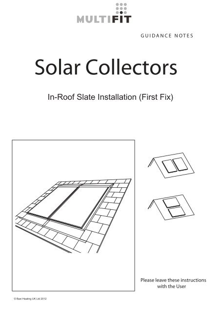
Solar Collectors<br />
<strong>In</strong>-Roof Slate <strong>In</strong>stallation <strong>In</strong>stallation (First (First Fix) Fix)<br />
Please leave these <strong>instructions</strong><br />
with the User<br />
©<br />
©<br />
<strong>Baxi</strong><br />
<strong>Baxi</strong><br />
Heating<br />
Heating<br />
UK Ltd<br />
UK<br />
2011<br />
Ltd 2012
Contents<br />
1.0<br />
2.0<br />
3.0<br />
4.0<br />
4.1<br />
5.0<br />
6.0<br />
7.0<br />
8.0<br />
Symbols and tools<br />
Health and safety<br />
Weight and dimensions<br />
Kit Contents and Components<br />
Hydraulic kit contents and components<br />
<strong>In</strong>stallation<br />
Snow and Wind Load<br />
Legislation, recommendations and maintenance<br />
Notes<br />
4<br />
5<br />
6<br />
8<br />
10<br />
11<br />
28<br />
29<br />
30
1.0 Symbols<br />
Tools<br />
Caution<br />
Screwdriver<br />
<strong>In</strong>formation<br />
Spanner Tight<br />
1 Collector<br />
Drill / Diver<br />
2 Collectors<br />
Meter tape<br />
+<br />
Extention of the collector<br />
Hammer<br />
Page Reference Number<br />
Tile cutter<br />
Material purchased separately<br />
Tin Snips<br />
Weight<br />
01<br />
bar<br />
0<br />
Maximum pressure<br />
Measure<br />
Supplied separately<br />
Remove plastic<br />
4
Health and safety<br />
2.0<br />
Use safety helmet.<br />
Danger of lightning in stormy weather<br />
Use safety shoes.<br />
kg<br />
Heavy load<br />
Beware of tripping<br />
Use safety harness for protection against<br />
falling.<br />
Beware of slippery surfaces<br />
Use safety gloves.<br />
Beware of high temperatures<br />
Use safety goggles.<br />
<strong>In</strong>clude the collector in the lightning protection<br />
device of the building.<br />
Handle collector by grasping the profile<br />
5
3.0<br />
Weight and dimensions<br />
x<br />
y<br />
z<br />
(kg) (bar) x (mm) y (mm) z (mm) w (mm)<br />
01 0 bar<br />
SOL 200 P 35 10 1147 1753 87 2387<br />
SOL 200 L 36 10 1753 1147 87 1785<br />
SOL 250 P 48 10 1147 2187 87 2825<br />
>500mm<br />
>350mm<br />
>500mm<br />
>500mm<br />
kg<br />
6
3.0<br />
245<br />
x<br />
245<br />
w<br />
245<br />
x<br />
40<br />
x<br />
245<br />
w<br />
245<br />
x<br />
40<br />
x<br />
x<br />
245<br />
w<br />
+ . . . +<br />
kg<br />
7
4.0 Kit Contents and Components<br />
+<br />
SOL 200 P<br />
SOL 250 P<br />
SOL 200 L<br />
SOL 200 P<br />
SOL 250 P<br />
SOL 200 L<br />
SOL 200 P<br />
SOL 250 P<br />
SOL 200 L<br />
A<br />
B<br />
C<br />
D<br />
E<br />
F<br />
- - - 3 3 3 3 3 3<br />
6 6 6 6 6 6 - - -<br />
2 2 2 3 3 3 1 1 1<br />
1 1 1 2 2 2 1 1 1<br />
1 1 1 1 1 1 - - -<br />
1 1 1 1 1 1 - - -<br />
A- <strong>In</strong>termediate Clamp<br />
B- Side Clamp<br />
C- Bottom Bracket<br />
D- Top Panel<br />
E- Top Corner L/H<br />
F- Top Corner R/H<br />
G- Top <strong>In</strong>fill Section<br />
H- Side Cover L/H<br />
J- Side Cover R/H<br />
K- Middle <strong>In</strong>fill Section<br />
L- Bottom Section<br />
M- Bottom Corner L/H<br />
N- Bottom Corner R/H<br />
O- Bottom infill piece<br />
P- Batten<br />
Q- Wood screw L=35mm<br />
R- Wood screw L=70mm<br />
S- Coloured self drilling screw<br />
T- Coloured waterp<strong>roof</strong> washers<br />
U- Nail<br />
V- <strong>In</strong>structions<br />
W- Side Lower<br />
XA- Soaker L/H<br />
XB- Soaker R/H<br />
YA- Soaker top corner L/H<br />
YB- Soaker top corner R/H<br />
G<br />
- - - 1 1 1 1 1 1<br />
H<br />
1 1 1 1 1 1 - - -<br />
J<br />
1 1 1 1 1 1 - - -<br />
K<br />
- - - 1 1 1 1 1 1<br />
L<br />
1 1 1 2 2 2 1 1 1<br />
M<br />
1 1 1 1 1 1 - - -<br />
N<br />
1 1 1 1 1 1 - - -<br />
O<br />
- - - 1 1 1 1 1 1<br />
P<br />
5 5 5 10 10 10 5 5 5<br />
8
YA<br />
E<br />
W<br />
H<br />
D<br />
G<br />
P<br />
4.0<br />
XA<br />
F<br />
M<br />
YB<br />
O<br />
K<br />
L<br />
J<br />
W<br />
C<br />
N<br />
XB<br />
S T<br />
Q<br />
A<br />
+<br />
SOL 200 P<br />
SOL 250 P<br />
SOL 200 L<br />
SOL 200 P<br />
SOL 250 P<br />
SOL 200 L<br />
SOL 200 P<br />
SOL 250 P<br />
SOL 200 L<br />
Q<br />
R<br />
16 16 16 24 24 24 8 8 8<br />
15 15 15 30 30 30 15 15 15<br />
S<br />
T<br />
U<br />
V<br />
14 14 14 19 19 19 5 5 5<br />
14 14 14 19 19 19 5 5 5<br />
6 6 6 6 6 6 - - -<br />
1 1 1 1 1 1 - - -<br />
B<br />
W<br />
2 2 2 2 2 2 - - -<br />
XA<br />
13 15 10 13 15 10 - - -<br />
XB<br />
YA<br />
YB<br />
13 15 10 13 15 10 - - -<br />
1 1 1 1 1 1 - - -<br />
1 1 1 1 1 1 - - -<br />
9
4.1<br />
Hydraulic kit contents and components<br />
S1- End Cap<br />
S2- Joining Piece<br />
S3- Elbow<br />
S4- Manual Air Vent (Optional part)<br />
S5- Tee Piece (Optional part)<br />
S6- Clip<br />
S7- Plug for manual Air Vent (Optional part)<br />
S8- Auto Air Vent (Optional part)<br />
S9- 2m Pipe Kit<br />
S10- Straight Connector with Fittings<br />
S11- Temperature Sensor<br />
S12- Sensor Elbow<br />
S1<br />
S2<br />
S3<br />
S4<br />
S5<br />
S6<br />
S7<br />
S8<br />
S9<br />
S10<br />
S11<br />
S12<br />
10
5.0 <strong>In</strong>stallation<br />
3<br />
R<br />
y4<br />
y3<br />
y1<br />
5.0<br />
α<br />
β<br />
y4<br />
y3<br />
y2<br />
y1<br />
α =<br />
β =<br />
η+ 80mm<br />
Q<br />
1<br />
C<br />
η<br />
x<br />
7<br />
x<br />
2<br />
x<br />
= α<br />
= β<br />
3<br />
β<br />
α<br />
13
5.0 <strong>In</strong>stallation<br />
Q<br />
B<br />
4 5<br />
14
5.0<br />
4<br />
5<br />
Q<br />
B<br />
15
5.0 <strong>In</strong>stallation<br />
Q<br />
A<br />
6<br />
7<br />
S5<br />
8<br />
16
5.0<br />
Q<br />
B<br />
9<br />
40mm<br />
17
5.0<br />
<strong>In</strong>stallation<br />
&<br />
18
5.0<br />
1<br />
L<br />
2<br />
N<br />
T S<br />
3<br />
M<br />
19
5.0<br />
<strong>In</strong>stallation<br />
4<br />
O<br />
K<br />
5<br />
T<br />
S<br />
20
5.0<br />
6<br />
W<br />
7<br />
U<br />
U<br />
21
5.0 <strong>In</strong>stallation<br />
8<br />
a<br />
XA/XB<br />
b<br />
22
5.0<br />
9<br />
10<br />
YA/YB<br />
11 12<br />
J<br />
H<br />
S<br />
T<br />
23
5.0 <strong>In</strong>stallation<br />
F<br />
1<br />
D<br />
D<br />
F<br />
2<br />
24
T<br />
S<br />
5.0<br />
3<br />
G<br />
4<br />
D<br />
D<br />
F<br />
+...+<br />
25
5.0<br />
<strong>In</strong>stallation<br />
5<br />
180º<br />
6<br />
T<br />
S<br />
26
5.0<br />
E<br />
7<br />
D<br />
T S<br />
8<br />
9<br />
≥150mm<br />
27
6.0<br />
Snow and Wind Load<br />
EN1991<br />
Design limit snow load on the ground = 2.8 kN/m²<br />
NOTE: This limit will be reduced for installations where abutments<br />
create additional risks of drifting or falling snow.<br />
The maximum wind load to be borne by the mounting structure<br />
depends on the height and geographical area of the site among<br />
other factors This structure must be installed in accordance with<br />
the provisions of the EN1991 standard. Consult your official dealer<br />
if in doubt.<br />
28
Legislation, recommendations and maintenance<br />
7.0<br />
LEGISLATION<br />
Please note the following <strong>instructions</strong> regarding laws, regulations and technical rules.<br />
When setting up solar energy installations, the laws and regulations at local, state, European<br />
and international level that apply to the country in question must be observed. Generally acknowledged<br />
technical regulations apply; these are usually formulated in the form of standards,<br />
guidelines, provisions, regulations and technical rules laid down by local and national bodies,<br />
energy supply companies, trade organisations and technical committees in the relevant fields.<br />
The installation of solar units may require improved rain resistance with regard to <strong>roof</strong>, wall and<br />
sealing technology and this must be taken into account accordingly. To meet regulations for<br />
the prevention of accidents, it may be necessary to use safety equipment (straps, scaffolding,<br />
supports, etc.). Such safety equipment is not supplied. <strong>In</strong>stallation must only be carried out<br />
by technically qualified and authorised personnel with a recognised qualification (verified by a<br />
state or national body) in the relevant technical area.<br />
This product is unclassified against BS 476-3.<br />
RECOMMENDATIONS<br />
- Use a safety harness when working at height.<br />
- The structure of the <strong>roof</strong> must be assessed for its suitability prior to commencing work.<br />
- Consult a structural Engineer if you are unsure of the collector’s siting.<br />
- Loading due to snow may exceed the capability of the property’s structure.<br />
- Wind loads may cause excess forces on the structure and cause damage.<br />
- The installer is responsible for the suitability of the site and its sub-structure.<br />
- The collector should be sited to avoid damage from falling debris and vandalism.<br />
- All pipe work within this installation must be earth bonded.<br />
- <strong>In</strong> exposed areas, the collector must be protected against the risk of lightning.<br />
- It is recommended that a minimum of 2 people are used to lift this product.<br />
- The collector must not be lifted by its pipe connections.<br />
- Ensure all hydraulic connections are securely fixed and are free of leaks.<br />
- Avoid installing the collector in shaded areas.<br />
- The system must be inspected on completion of the work.<br />
- A further inspection is recommended annually.<br />
- Do not apply excessive force when installing the collector.<br />
- Hot, exposed surfaces that can be touched must be insulated to protect against injury.<br />
- Lubrication is not required for the ‘O’ ring connections.<br />
- The collector must not be installed on an uneven <strong>roof</strong> surface.<br />
- Large arrays will require specialist piping, pump groups and design.<br />
- The flashing kit must be installed correctly to prevent water damage to the property.<br />
- The flashing kit is only recommended for <strong>roof</strong>s with waterp<strong>roof</strong> membrane or underfelt.<br />
- Prepare the <strong>roof</strong> with a weatherp<strong>roof</strong> membrane (felt or alternative material) before installing<br />
the collectors.<br />
- For concrete <strong>roof</strong> the supplied battens must not be installed. The panel and the <strong>In</strong> Roof kit are<br />
installed directly to the concrete <strong>roof</strong>.<br />
- An anchor plug and bolt may be used to secure the collector on a suitable <strong>roof</strong> surface.<br />
-The illustrations in this manual may differ from the equipment supplied.<br />
-The company cannot be held responsible for any differences between the images in the manual<br />
and the actual assembly.<br />
MAINTENANCE<br />
It is recommended that the following checks are carried out on an annual basis:<br />
1) Check the collector installation for any signs of damage or any build up of debris.<br />
2) Check for any corrosion to the collector or the mounting system and repair if necessary.<br />
3) Check the tightness of the fasteners. Where fasteners cannot be readily accessed, the<br />
overall security of the collector installation may indicate whether problems exist.<br />
4) Check the fittings and pipe work for any signs of fluid leakage or damage, including the<br />
condition of the pipe insulation, and repair if necessary. Check inside the building for any<br />
evidence of leaks.<br />
5) Examine the <strong>roof</strong> tiles around the collector installation for any damage or deterioration, and<br />
repair if necessary.<br />
6 )Check for any foliage growth that may cause shading of the collectors.<br />
7) Where applicable, check the condition of any ballast used to secure the system.<br />
8) <strong>In</strong> areas where there may be a build up of dirt on the collector, only nonabrasive cleaning<br />
materials and methods should be used to clean the collectors and mounting system components.<br />
29
8.0 Notes<br />
30
31<br />
8.0
All descriptions and illustrations provided in this leaflet have been carefully<br />
prepared but we reserve the right to make changes and improvements in<br />
our products which may affect the accuracy of the information contained in<br />
this leaflet. All goods are sold subject to our standard Conditions of Sale<br />
which are available on request.<br />
MULTIFIT<br />
A Trading Division of <strong>Baxi</strong> Heating UK Ltd (3879156)<br />
Brooks House, Coventry Road, Warwick. CV34 4LL<br />
Technical Enquiries 0844 871 1568<br />
Website www.bdrthermea.com<br />
e&oe<br />
© <strong>Baxi</strong> Heating UK Ltd 2012<br />
720799503<br />
SP Comp No 720799503e (04/12)