Dachs mini-CHP Brochure - Baxi Know How
Dachs mini-CHP Brochure - Baxi Know How
Dachs mini-CHP Brochure - Baxi Know How
- No tags were found...
You also want an ePaper? Increase the reach of your titles
YUMPU automatically turns print PDFs into web optimized ePapers that Google loves.
<strong>CHP</strong><br />
Combined Heat<br />
and Power<br />
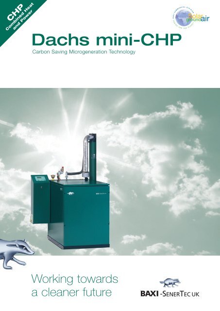
<strong>Dachs</strong> <strong>mini</strong>-<strong>CHP</strong><br />
Carbon Saving Microgeneration Technology<br />
Working towards<br />
a cleaner future
<strong>Dachs</strong> <strong>mini</strong>-<strong>CHP</strong><br />
Carbon Saving Microgeneration Technology<br />
What is micro-<strong>CHP</strong><br />
Our grid electricity is generated by large, remote power<br />
stations which every year waste enough energy to heat<br />
most of our buildings. This huge waste of energy results in<br />
very inefficient and very expensive grid supplied electricity.<br />
HUGE HEAT LOSSES<br />
Micro-Combined Heat and Power is the simultaneous<br />
generation of principally electricity, and also of heat, close<br />
to the point of use. By locating micro-<strong>CHP</strong> equipment in<br />
or close to a building, the electricity generated and the<br />
heat produced can be used in the building with no<br />
energy wastage.<br />
Gas inlet<br />
MSR2<br />
Controller<br />
Water cooled<br />
asynchronous<br />
generator<br />
1070 mm<br />
Exhaust heat<br />
exchanger<br />
Single cylinder<br />
4-stroke engine<br />
720 mm<br />
Carbon saving technology<br />
Micro-<strong>CHP</strong> is a key microgeneration<br />
technology which can deliver carbon<br />
savings of 20%-30%. It is a mature,<br />
reliable technology which delivers very<br />
attractive financial benefits and can<br />
play a big part in gaining compliance<br />
with planning and Building Regulations.<br />
<strong>Dachs</strong> <strong>mini</strong>-<strong>CHP</strong><br />
The <strong>Dachs</strong> is manufactured by SenerTec<br />
GmbH, a BDR Thermea Group company,<br />
and is Europe’s biggest selling <strong>CHP</strong> unit.<br />
Over 25,000 <strong>Dachs</strong> have saved more than<br />
one million tonnes of CO 2 and generated<br />
over 2 GWh of low cost electricity.<br />
The <strong>Dachs</strong> is designed for continuous<br />
running. The reliable internal combustion<br />
engine drives a maintenance-free, 3-phase<br />
electrical generator, and the heat generated<br />
by the engine is captured and transferred<br />
to the building’s heating system.<br />
Selecting a <strong>Dachs</strong><br />
The key to a successful <strong>CHP</strong> installation<br />
is to make sure that the engine runs for<br />
as long as possible to generate valuable,<br />
low cost electricity.<br />
Therefore, it is essential to know that<br />
the heat produced by the engine can be<br />
used in the building at all times. If the<br />
building’s heat or hot water demand falls<br />
below the <strong>mini</strong>mum heat output of the<br />
<strong>CHP</strong>, it will switch off until the heat<br />
demand is re-established. This will<br />
mean loss of electricity generation.<br />
It is important to calculate the<br />
<strong>mini</strong>mum, or base, heat demand of the<br />
building and select the number of <strong>Dachs</strong><br />
modules to meet this requirement. If<br />
there is a fairly constant base demand,<br />
eg. for domestic hot water generation or<br />
for a swimming pool, the <strong>CHP</strong> will<br />
operate for long periods. If sufficient<br />
additional heat demand exists, it might<br />
be considered suitable to increase the<br />
number of <strong>CHP</strong> modules above the base<br />
demand requirements, but make sure<br />
that there is sufficient demand for most<br />
of the electricity generated.<br />
Key design points<br />
• Match the <strong>CHP</strong> output to the building’s<br />
base heat load.<br />
• keep it small – if there’s no demand<br />
for its heat, it won’t run.<br />
• schedule <strong>CHP</strong> as the lead ’boiler’<br />
– this extends running time.<br />
Applications<br />
• Sheltered housing • Apartment blocks<br />
• Leisure centres • Luxury houses<br />
• Fire stations • Hospitals • Prisons<br />
• Schools • Hotels • Nursing Homes<br />
• Student Accomodation
Typical installation<br />
Installing a <strong>Dachs</strong><br />
Installation of a <strong>Dachs</strong> into a new or<br />
existing heating system is very<br />
straightforward, requiring a fuel supply,<br />
flow & return connections to a primary<br />
heating circuit, and an exhaust or flue<br />
gas pipe to outside.<br />
The <strong>Dachs</strong> electrical interface complies<br />
with the G83/1-1 Engineering<br />
Recommendation which permits direct<br />
connection of the generator to the<br />
building’s circuits, and hence parallel<br />
connection with the public grid network.<br />
The grid will make up any power shortfall<br />
from the <strong>CHP</strong>, and any excess power<br />
generated by the <strong>CHP</strong> will be<br />
automatically exported to the grid.<br />
<strong>Dachs</strong> SE Condensing<br />
The SE buffer vessel keeps the <strong>Dachs</strong><br />
running when temporary heat demand<br />
reductions might otherwise switch it<br />
off for short periods. By avoiding<br />
unnecessary stop/start cycling, the<br />
engine stays in peak condition with no<br />
loss of efficiency.<br />
The condenser recovers heat from the<br />
engine exhaust, increasing the overall<br />
efficiency of the <strong>Dachs</strong> to over 90%. The<br />
condenser should always be included<br />
when condensing boilers are installed.<br />
After passing through the condenser,<br />
the low temperature exhaust gas can be<br />
transported outside the building with<br />
plastic pipe.<br />
The <strong>Dachs</strong> SE Condensing package<br />
includes a <strong>Dachs</strong> with a buffer and<br />
condenser and all interconnecting<br />
hydraulic and exhaust gas pipes.<br />
Condenser exhaust flue<br />
The condenser plastic flue can terminate<br />
through the wall of the building (see<br />
example below), through the roof, or can<br />
be installed vertically on the external wall<br />
in accordance with flueing and planning<br />
regulations and the requirements of<br />
the building.<br />
Multi-module <strong>Dachs</strong><br />
For larger buildings, or buildings with<br />
higher heat and electrical demands, the<br />
<strong>Dachs</strong> can be installed in systems of up<br />
to 10 modules. The operational software<br />
sequence controls the multi-modules to<br />
ensure optimum operational efficiency<br />
and to <strong>mini</strong>mise servicing requirements.<br />
This approach avoids the ineffiencies that<br />
can occur when larger units modulate to<br />
meet lower output requirements, and<br />
consequently delivers greater flexibility<br />
to meet changing load patterns.<br />
Up to 3 <strong>Dachs</strong> modules can be<br />
connected to one buffer vessel offering<br />
a totally flexible solution to meet future<br />
expansion needs.<br />
<strong>Dachs</strong>Portal<br />
Every <strong>Dachs</strong> can be fitted with an<br />
analogue, GSM or ethernet modem<br />
allowing remote user communication via<br />
a portal on our website. The <strong>Dachs</strong> can<br />
be monitored to ensure correct operation,<br />
operational data can be viewed and<br />
downloaded, and fault and service<br />
signals will be automatically transmitted.
Technical Data<br />
Electrical output (3-phase)<br />
5.5 kW<br />
Thermal output without condenser<br />
12.5 kW<br />
Thermal output with condenser (maximum)<br />
15.5.kW<br />
Efficiency without condenser – gross (nett) 79% (88%)<br />
Max. efficiency with condenser – gross (nett) 92% (102%)<br />
Height (to top of casing)<br />
1000 mm<br />
Width (excl. MSR2 controller)<br />
720 mm<br />
Depth<br />
1060 mm<br />
Delivered weight<br />
530 kg<br />
Standard safety valve<br />
2.5 bar<br />
Max. working pessure (4.5 bar SV reqd.)<br />
5.0 bar<br />
Gas supply pressure<br />
20 mbar<br />
Natural gas input (22.8 kW) 2.13 m 3 /h<br />
Plant room air inlet 150cm 2<br />
Noise emission (at 1 metre from casing)<br />
52-56 dBA<br />
Service intervals<br />
3,500 hrs<br />
Designed service life<br />
80,000 hrs<br />
Heating F&R connections (flexibles supplied) 1”<br />
Gas connection (flexible supplied) ½”<br />
Non-condensing exhaust (steel pipe not supplied) 1”<br />
Condenser exhaust (plastic flue available)<br />
DN80<br />
Heating flow temperature 80ºC<br />
Max. heating return temperature (to allow <strong>CHP</strong> to operate) 70ºC<br />
Electrical connections:<br />
– 3-phase supply onto 20A type ‘C’ circuit breakers 2.5 mm<br />
– equipotential bonding to main earth 10 mm<br />
BMS control connections:<br />
– Volt free enable<br />
– 230 volt remote fault indication<br />
– 230 volt remote service due indication<br />
Modem connection – optional analogue, GSM or ethernet<br />
SE Buffer Vessel – Key Data<br />
Capacity<br />
750 litres<br />
Height (with insulation)<br />
1920 mm<br />
Diameter (excluding insulation)<br />
750 mm<br />
Diameter (with insulation)<br />
950 mm<br />
Insulation<br />
100 mm<br />
Weight (excluding insulation)<br />
140 kg<br />
Max. hydraulic W.P.<br />
3.0 bar<br />
Heating F&R connections to DACHS 1”<br />
F&R connections to heating system 1½”<br />
Heating flow temperature 80ºC<br />
Max. heating return temp. 70ºC<br />
Condenser – Key Data<br />
Additional heat output:<br />
– at 60ºC return temp. 0.8 kW<br />
– at 50ºC return temp. 0.9 kW<br />
– at 35ºC return temp. 2.3 kW<br />
– at 20ºC return temp. 3.0 kW<br />
Height<br />
1750 mm<br />
Width<br />
400 mm<br />
Depth<br />
300 mm<br />
Top clearance required<br />
1000 mm<br />
Weight<br />
25 kg<br />
Max. hydraulic W.P.<br />
5.0 bar<br />
Heating F&R connections ½”<br />
Exhaust gas outlet (plastic)<br />
DN80<br />
Condensate drain<br />
25 mm.<br />
High limit safety ‘stat (STL) 110ºC<br />
Heating inlet temp. (return) 10ºC – 70ºC<br />
Typical hydraulic arrangement<br />
Space requirements<br />
80 o C<br />
Multi-module <strong>Dachs</strong> c/w condensers<br />
(base heat load)<br />
SE buffer<br />
750 litres<br />
Boilers<br />
(peak load)<br />


