Baseline Spec Template - NEXRAD Radar Operations Center - NOAA
Baseline Spec Template - NEXRAD Radar Operations Center - NOAA
Baseline Spec Template - NEXRAD Radar Operations Center - NOAA

You also want an ePaper? Increase the reach of your titles
YUMPU automatically turns print PDFs into web optimized ePapers that Google loves.
Document Number 2620003P<br />
Code Identification 0WY55<br />
WSR-88D ROC<br />
dd Month 2010<br />
RPG Build 12.0<br />
INTERFACE CONTROL DOCUMENT<br />
FOR THE<br />
PRODUCT SPECIFICATION<br />
Prepared by:<br />
WSR-88D <strong>Radar</strong> <strong>Operations</strong> <strong>Center</strong><br />
1313 Halley Circle<br />
Norman, OK 73069<br />
SUBMITTED BY &<br />
APPROVED FOR<br />
USE AS PRODUCT<br />
BASELINE BY:<br />
DATE:<br />
Cheryl A. Stephenson<br />
Team Leader, Configuration Management<br />
WSR-88D <strong>Radar</strong> <strong>Operations</strong> <strong>Center</strong><br />
DISTRIBUTION STATEMENT A: Approved for public release; distribution unlimited.
Document Number 2620003P<br />
Code Identification 0WY55<br />
WSR-88D ROC<br />
dd Month 2010<br />
RPG Build 12.0<br />
INTERFACE CONTROL DOCUMENT<br />
FOR THE PRODUCT SPECIFICATION<br />
2620003<br />
DOCUMENT REVISION RECORD FORM<br />
REVISION - A B C D E F G H I J K L M<br />
RELEASED BY ROC ROC ROC ROC ROC ROC ROC ROC ROC ROC ROC ROC ROC ROC<br />
RELEASE 03/01/9 06/26/9 09/11/0 01/27/0 06/19/0 12/29/0 06/13/0 01/30/0 07/29/0 4/13/05 2/8/06 5/25/07 3/25/08 3/3/09<br />
DATE<br />
6 8 1 2 2 2 3 4 4<br />
EFFECTIVITY 03/01/9 06/26/9 09/11/0 01/27/0 06/19/0 12/29/0 06/13/0 01/30/0 07/29/0 4/13/05 2/8/06 5/25/07 3/25/08 3/3/09<br />
6 8 1 2 2 2 3 4 4<br />
AUTHORITY F0048 F0095 F0103 F0158 F0164 F0174 F0182 F0185 F0186 F0209 F0126/ F0250 F0286 0349<br />
F0210<br />
FAST TRACK NO NO NO NO ROC ROC ROC ROC ROC ROC ROC ROC ROC ROC<br />
REV HISTORY<br />
BLD BLD<br />
9.0 10.0<br />
- A<br />
BLD<br />
1.0<br />
BLD<br />
1.2<br />
BLD<br />
2.0<br />
BLD<br />
3.0<br />
INTRODUCTIO<br />
N<br />
SCOPE - A<br />
Section 1.0 - A C D L<br />
Section 2.0 - A C D L<br />
Section 3.0 - A D L<br />
Section 4.0 - A D I L<br />
Section 5.0 - A D F<br />
Section 6.0 - A B D<br />
Section 7.0 - A D F<br />
Section 8.0 - A D<br />
Section 9.0 - A D F<br />
Section 10.0 - A D<br />
Section 11.0 - A D G<br />
Section 12.0 - A D E H<br />
Section 13.0 - A D F<br />
Section 14.0 - A D F<br />
Section 15.0 - A D F<br />
Section 16.0 - A D<br />
Section 17.0 - A D<br />
Section 18.0 - A D H I<br />
Section 19.0 - A D<br />
Section 20.0 - A D F G H J L<br />
Section 21.0 - A D G I L<br />
Section 22.0 - A D I<br />
Section 23.0 - A D<br />
Section 24.0 - A D<br />
Section 25.0 - A D<br />
Section 26.0 - A D G H I J<br />
Section 27.0 - A D I<br />
Section 28.0 - A D G L<br />
Section 29.0 - A D E G I K L<br />
Section 30.0 - A D G<br />
Section 31.0 - A D G I<br />
Section 32.0 - A D<br />
Section 33.0 - A D E G L<br />
Section 34.0 - A D I L M<br />
Section 35.0 N/A N/A B D<br />
Section 36.0 D H I<br />
Section 37.0 D H I<br />
Section 38.0<br />
D<br />
Section 39.0 D K<br />
Section 40.0 E G<br />
Section 41.0 F L<br />
Section 42.0<br />
H<br />
Section 43.0<br />
H<br />
Section 44.0<br />
H<br />
Section 45.0<br />
J<br />
Section 46.0 K L<br />
Section 47.0<br />
L<br />
Appendix A - A F G H I L<br />
Appendix B - A F G L<br />
Appendix C D E F G I<br />
Appendix D H Delete<br />
d<br />
BLD<br />
4.0<br />
BLD<br />
5.0<br />
BLD<br />
6.0<br />
BLD<br />
7.0<br />
BLD<br />
8.0<br />
BLD<br />
9.0<br />
BLD<br />
10.0<br />
BLD<br />
11.0<br />
R-1
Document Number 2620003P<br />
Code Identification 0WY55<br />
WSR-88D ROC<br />
dd Month 2010<br />
RPG Build 12.0<br />
REVISION N P<br />
RELEASED BY ROC ROC<br />
RELEASE 11/04/0 //2010<br />
DATE<br />
9<br />
EFFECTIVITY 11/04/0 //2010<br />
9<br />
AUTHORITY 0445<br />
FAST TRACK NO NO<br />
REV HISTORY RPG<br />
BLD<br />
11.2<br />
RPG<br />
BLD<br />
12.0<br />
INTRODUCTIO<br />
N<br />
SCOPE<br />
Section 1.0 N<br />
Section 2.0 N<br />
Section 3.0<br />
Section 4.0<br />
Section 5.0<br />
Section 6.0<br />
Section 7.0<br />
Section 8.0<br />
Section 9.0<br />
Section 10.0<br />
Section 11.0<br />
Section 12.0<br />
Section 13.0<br />
Section 14.0<br />
Section 15.0<br />
Section 16.0<br />
Section 17.0<br />
Section 18.0<br />
Section 19.0<br />
Section 20.0<br />
Section 21.0<br />
Section 22.0<br />
Section 23.0<br />
Section 24.0<br />
Section 25.0<br />
Section 26.0<br />
Section 27.0<br />
Section 28.0<br />
Section 29.0<br />
Section 30.0<br />
Section 31.0<br />
Section 32.0<br />
Section 33.0<br />
Section 34.0<br />
Section 35.0<br />
Section 36.0<br />
Section 37.0<br />
Section 38.0<br />
Section 39.0<br />
Section 40.0<br />
Section 41.0<br />
Section 42.0<br />
Section 43.0<br />
Section 44.0<br />
Section 45.0<br />
Section 46.0<br />
Section 47.0<br />
Section 48.0<br />
P<br />
Section 49.0<br />
P<br />
Section 50.0<br />
P<br />
Section 51.0<br />
P<br />
Section 52.0<br />
P<br />
Section 53.0<br />
P<br />
Section 54.0<br />
P<br />
Section 55.0<br />
P<br />
Section 56.0<br />
P<br />
Section 57.0<br />
P<br />
Section 58.0<br />
P<br />
Section 59.0<br />
P<br />
Section 60.0<br />
P<br />
Appendix A<br />
Appendix B<br />
Appendix C<br />
P<br />
R-2
Document Number 2620003P<br />
Code Identification 0WY55<br />
WSR-88D ROC<br />
dd Month 2010<br />
RPG Build 12.0<br />
Appendix D<br />
R-3
Table of Contents<br />
1 REFLECTIVITY (R, DR, DR7 and SDR).........................................................................................1-1<br />
2 MEAN RADIAL VELOCITY (V, DV, DV7 and SDV) .....................................................................2-1<br />
3 SPECTRUM WIDTH (SW and SDW) .............................................................................................3-1<br />
4 DELETED..........................................................................................................................................4-1<br />
5 DELETED..........................................................................................................................................5-1<br />
6 COMPOSITE REFLECTIVITY and COMPOSITE REFLECTIVITY EDITED FOR<br />
ANOMALOUS PROPAGATION (CR and CRE).....................................................................................6-1<br />
7 DELETED..........................................................................................................................................7-1<br />
8 ECHO TOPS (ET)..............................................................................................................................8-1<br />
9 DELETED..........................................................................................................................................9-1<br />
10 DELETED ....................................................................................................................................10-1<br />
11 DELETED ....................................................................................................................................11-1<br />
12 VELOCITY AZIMUTH DISPLAY (VAD), (VWP)......................................................................12-1<br />
13 DELETED ....................................................................................................................................13-1<br />
14 CROSS SECTION (RCS, VCS) ...................................................................................................14-1<br />
15 DELETED ....................................................................................................................................15-1<br />
16 STORM RELATIVE MEAN RADIAL VELOCITY (SRM, SRR)...............................................16-1<br />
17 VERTICALLY INTEGRATED LIQUID (VIL)...........................................................................17-1<br />
18 STORM TRACKING INFORMATION (STI) .............................................................................18-1<br />
19 HAIL INDEX (HI)........................................................................................................................19-1<br />
20 MESOCYCLONE (M, MRU, MD, DMD)...................................................................................20-1<br />
21 TORNADO VORTEX SIGNATURE (TVS) ................................................................................21-1<br />
22 STORM STRUCTURE (SS).........................................................................................................22-1<br />
23 LAYER COMPOSITE REFLECTIVITY (LRM, LRA, APR) .....................................................23-1<br />
24 DELETED ....................................................................................................................................24-1<br />
25 USER ALERT MESSAGE (UAM) ..............................................................................................25-1<br />
26 RADAR CODED MESSAGE (RCM)...........................................................................................26-1<br />
27 FREE TEXT MESSAGE (PTM, FTM)........................................................................................27-1<br />
28 SURFACE RAINFALL ACCUMULATION (OHP, THP) .........................................................28-1<br />
29 STORM TOTAL RAINFALL ACCUMULATION (STP and DSP)............................................29-1<br />
30 HOURLY DIGITAL PRECIPITATION ARRAY (DPA).............................................................30-1<br />
31 SUPPLEMENTAL PRECIPITATION DATA (SPD) .................................................................31-1<br />
32 USER SELECTABLE RAINFALL ACCUMULATION (USP) .................................................32-1<br />
33 HYBRID SCAN REFLECTIVITY (HSR) and DIGITAL HYBRID SCAN REFLECTIVITY<br />
(DHR)33-1<br />
34 CLUTTER FILTER CONTROL..................................................................................................34-1<br />
35 ITWS Digital Base Velocity (ITWSDBV) ...................................................................................35-1<br />
36 Clutter Likelihood Reflectivity (CLR) ........................................................................................36-1<br />
37 Clutter Likelihood Doppler (CLD) ..............................................................................................37-1<br />
38 SUPEROB ....................................................................................................................................38-1<br />
39 Digital High Resolution Vertically Integrated Liquid (HRVIL)...............................................39-1<br />
40 User Selectable Layer Composite Reflectivity (ULR) ...............................................................40-1<br />
41 Digital High Resolution Enhanced Echo Tops (HREET) ..........................................................41-1<br />
42 One Hour Snow Accumulation (OSW, OSD)..............................................................................42-1<br />
43 Storm Total Snow Accumulation (SSW and SSD).....................................................................43-1<br />
44 User Selectable Snow Accumulation (USW, USD)....................................................................44-1<br />
45 Archive III Status Product (ASP) ...............................................................................................45-1<br />
46 Gust Front MIGFA (GFM) ..........................................................................................................46-1<br />
47 <strong>NEXRAD</strong> TURBULENCE DETECTION ALGORITHM (EDR, EDC).....................................47-1<br />
48 DIFFERENTIAL REFLECTIVITY (ZDR, DZD)........................................................................48-1<br />
49 CORRELATION COEFFICIENT (CC, DCC) ............................................................................49-1<br />
50 SPECIFIC DIFFERENTIAL PHASE (KDP, DKD)...................................................................50-1<br />
i
51 HYDROMETEOR CLASSIFICATION (HC, DHC, HHC).........................................................51-1<br />
52 MELTING LAYER (ML) .............................................................................................................52-1<br />
53 ONE-HOUR ACCUMULATION (OHA).....................................................................................53-1<br />
54 DIGITAL ACCUMULATION ARRAY (DAA) ............................................................................54-1<br />
55 STORM TOTAL ACCUMULATION (STA)................................................................................55-1<br />
56 DIGITAL STORM TOTAL ACCUMULATION (DSA) ..............................................................56-1<br />
57 DIGITAL USER-SELECTABLE ACCUMULATION (DUA)....................................................57-1<br />
58 DIGITAL ONE-HOUR DIFFERENCE (DOD) ..........................................................................58-1<br />
59 DIGITAL STORM TOTAL DIFFERENCE (DSD).....................................................................59-1<br />
60 DIGITAL INSTANTANEOUS PRECIPITATION RATE (DPR) ..............................................60-1<br />
APPENDIX A........................................................................................................................................... A-1<br />
APPENDIX B........................................................................................................................................... B-1<br />
APPENDIX C........................................................................................................................................... C-1<br />
Index of Tables<br />
TABLE I. PARAMETER STANDARD DIMENSIONS FOR DISPLAY.............................................. A-5<br />
TABLE II. PRODUCT PARAMETERS................................................................................................ A-7<br />
TABLE III. STANDARD ABBREVIATIONS .................................................................................... A-11<br />
Index of Figures<br />
Format I. Full Screen ............................................................................................................................. B-1<br />
Format Ia. Full Screen (Status and Annotation Area)......................................................................... B-2<br />
Format Ib. Status and Annotation Area (Parameter Select Mode)..................................................... B-3<br />
Format II. Quarter Screen ...................................................................................................................... B-4<br />
Format IIa: Quarter Screen Layout .................................................................................................. B-5<br />
Format IIb. Quarter Screen Window/Non-Window Products............................................................ B-6<br />
Format III. Attribute Area..................................................................................................................... B-7<br />
Format IVA VWP Grid........................................................................................................................... B-8<br />
Format IVb. VAD Grid ........................................................................................................................... B-9<br />
Format V. Cross-Section Grid.............................................................................................................. B-10<br />
Format I. Storm Tracking .................................................................................................................... C-1<br />
Format I. Storm Tracking .................................................................................................................... C-1<br />
Format II. Hail Index ............................................................................................................................ C-2<br />
Format II Hail Index .............................................................................................................................. C-2<br />
Format III. Mesocyclone....................................................................................................................... C-2<br />
Format III Mesocyclone.......................................................................................................................... C-3<br />
Format IIIb. Mesocyclone Rapid Update (Sheet 1 of 1) ..................................................................... C-3<br />
Format IIIc. Mesocyclone Detection (Sheet 1 of 1)............................................................................. C-3<br />
TORNADO VORTEX SIGNATURE ADAPTATION PARAMETERS.................................................. C-4<br />
Format IV. TVS....................................................................................................................................... C-4<br />
Format IVb. TVS Rapid Update ............................................................................................................. C-4<br />
Format V. Storm Structure.................................................................................................................... C-5<br />
FORMAT VI SPD (Sheet 1 of 2).............................................................................................................. C-5<br />
FORMAT VI. SPD (sheet 2 of 2) ............................................................................................................ C-5<br />
Format VII. DPA...................................................................................................................................... C-7<br />
Format VIII. DHR and DSP.................................................................................................................... C-8<br />
Format IX Precipitation Adaptation Data (sheet 1 of 4)...................................................................... C-9<br />
Format IX Precipitation Adaptation Data (sheet 2 of 4)..................................................................... C-9<br />
Format IX Precipitation Adaptation Data (sheet 3 of 4)..................................................................... C-9<br />
Format IX Precipitation Adaptation Data (sheet 4 of 4)...................................................................... C-9<br />
ii
Format X for VAD Wind Data to VWP Tabular Alphanumeric Block (TAB) (Sheet 1 of 3)............ C-10<br />
Format X Wind Profile Adaptable Parameters (Sheet 2 of 3) ........................................................ C-10<br />
Format X Wind Profile Adaptable Parameters (Sheet 3 of 3) .......................................................... C-10<br />
Format XI <strong>Radar</strong> Echo Classifier Adaptable Parameters (Sheet 1 of 1) ....................................... C-11<br />
FORMAT XII One-hour and Storm Total Snow Accumulation (sheet 1 of 2).................................. C-12<br />
FORMAT XII One-hour and Storm Total Snow Accumulation (sheet 2 of 2).................................. C-12<br />
FORMAT XIII User Selectable Snow Accumulation (sheet 1 of 2) .................................................. C-13<br />
FORMAT XIII User Selectable Snow Accumulation (sheet 2 of 2) .................................................. C-13<br />
Format XIV. Digital Storm Total Accumulation (DSA) ...................................................................... C-15<br />
Format XV: Storm Total Accumulation TAB (Sheet 1 of 3)................................................................ C-15<br />
Format XV: Storm Total Accumulation TAB (Sheet 2 of 3)................................................................ C-16<br />
Format XV: Storm Total Accumulation TAB (Sheet 3 of 3)................................................................ C-16<br />
iii
INTRODUCTION<br />
The Product <strong>Spec</strong>ification Interface Control Document is an internal engineering document for detail<br />
design criteria for the SS meteorological products.<br />
SCOPE<br />
The product descriptions and the product range/resolution of the 31 October 2001 issue of 2810000D,<br />
WSR-88D System <strong>Spec</strong>ification, form the basis for the product specification. The specifications<br />
define special symbols and characters.<br />
Appendix A contains standard and product specific units and dimensions, symbols, abbreviations,<br />
parameters and display features. These are also defined in each product specification.<br />
Appendix B contains product display formats. Alphanumeric tabular formats are contained in C.<br />
0-1
1 REFLECTIVITY (R, DR, DR7 AND SDR)<br />
1.1 SS Product Description<br />
"This product shall provide the reflectivity data displayable as an image 1 and formatted as a data<br />
array. For the image version, variations of the product shall be organized to provide various areas of<br />
coverage and display resolutions, while the data array version will provide the highest resolution<br />
available for the entire coverage area. 2 On Super-Resolution azimuth scans, variations of the data<br />
array version of the product shall be organized to provide super-resolution and legacy-resolution<br />
coverage and resolution requirements. Both versions will be limited to the lowest 70,000 feet AGL of<br />
the atmosphere. The product shall be generated for any azimuth scan at a single elevation angle<br />
based on user requirements. Each scan shall be updated once per volume scan time. 3 For the image<br />
version, each product shall be available for both 8 and 16 reflectivity data levels, while 256<br />
reflectivity data levels will be provided in the data array version. Each product shall include<br />
annotations for the product name, radar ID, time and date of scan, data level code, elevation angle,<br />
maximum data value (dBZ), radar position, radar elevation above MSL, and radar operational<br />
mode."<br />
Super-Resolution refers to the following three spatial resolution and coverage enhancements: 0.5deg<br />
azimuth sampling, 0.13nmi range sampling of Reflectivity, 162nmi coverage area for Mean Radial<br />
Velocity and <strong>Spec</strong>trum Width. The relevant distinction for Reflectivity is the reduced azimuth<br />
sample interval and range sample interval. “Super-Resolution” was introduced in 2008 (Build 10)<br />
and was optionally generated during “Split Cuts” processing (the lowest 2 or 3 elevation angles) as<br />
specified in the Volume Coverage Pattern definition.<br />
1.2 Display Format<br />
The product is displayable in full- or quarter-screen format (see Appendix B).<br />
1.2.1 Data Levels<br />
For the image version, the range of data level values (dBZ) varies with operational mode, area<br />
climatology and season, and with <strong>NEXRAD</strong> system (or agency) adaptation data. The range of<br />
reflectivity supported by the RDA is -32 to +95 dBZe.<br />
1.2.2 Color Level Code Tables<br />
The color level code used for display of the image version of reflectivity is <strong>NEXRAD</strong> (or agency)<br />
system adaptation data. Some examples of color tables for both Modes A and B are listed. With the<br />
exception of the end points, the lower value of the range is assigned to the individual colors<br />
displayed. The range of values for each is also indicated.<br />
- - - - - - -<br />
" 1 Defines the form of presentation on a graphic display; not necessarily the form of transmission."<br />
" 2 The exception is the Base Reflectivity Data Array (DoD Version - DR7) which limits the coverage<br />
area to 124 nmi."<br />
" 3 Defined in Appendix B"<br />
1-1
16-Level<br />
Code<br />
Display<br />
dBZ<br />
Color Level Codes<br />
Precipitation Mode<br />
Range<br />
dBZ<br />
Color Levels<br />
Code Color<br />
0 ND SNR
8-Level<br />
Code<br />
Precipitation Mode and Clear Air Mode<br />
Display Range<br />
dBZ<br />
dBZ<br />
Color Levels<br />
Code Color<br />
0 ND SNR
2 MEAN RADIAL VELOCITY (V, DV, DV7 AND SDV)<br />
2.1 SS Product Description<br />
"This product shall provide the mean radial velocity data both displayable as an image and<br />
formatted as a data array. For the image version, variations of the product shall be organized to<br />
provide various areas of coverage and display resolution, while the data array version will provide<br />
the highest resolution available for the entire radar coverage area. 1 On Super-Resolution azimuth<br />
scans, variations of the data array version of the product shall be organized to provide superresolution<br />
and legacy-resolution coverage and resolution requirements. Both versions will be limited<br />
to lowest 70,000 feet AGL of the atmosphere. The product shall be generated for any azimuth scan<br />
at a single elevation angle based on user requirements. Each scan shall be updated once per volume<br />
scan time. For the image version, each product shall include both 8 and 16 mean radial velocity data<br />
levels, while 256 velocity data levels will be provided in the data array version. Each product shall<br />
include annotations for the product name, radar ID, time and date of scan, data level code, elevation<br />
angle, maximum data value detected (knots, positive and negative), radar position, radar elevation<br />
above MSL, and radar operational mode."<br />
Super-Resolution refers to the following three spatial resolution and coverage enhancements: 0.5deg<br />
azimuth sampling, 0.13nmi range sampling of Reflectivity, 162nmi coverage area for Mean Radial<br />
Velocity and <strong>Spec</strong>trum Width. The relevant distinction for Mean Radial Velocity is the increased<br />
coverage area and reduced azimuth sample interval.<br />
2.2 Display Format<br />
The product is displayable in full- or quarter-screen format (see Appendix B).<br />
2.2.1 Data Levels<br />
For the image version, the range of mean radial velocity values will vary with operational mode and<br />
with <strong>NEXRAD</strong> system (or agency) adaptation data. The data thresholds are site adaptable.<br />
The range of values used is a function of meteorological mode and/or operator option.<br />
2.2.2 Color Level Code Tables<br />
The color level code used for display of the image version of mean radial velocity is <strong>NEXRAD</strong> system<br />
(or agency) adaptation data. Examples for currently defined color tables are shown. With the<br />
exception of end point values the lower value of the velocity range is assigned to the individual colors<br />
displayed. The range of values for each is also indicated.<br />
" 1 The range resolution for the Base Velocity Data Array (DoD Version - DV7) is 0.27 nmi."<br />
2-1
Color Level Codes<br />
16-Level Display<br />
Code knots<br />
Range<br />
knots<br />
Color Levels<br />
Code Color<br />
0 ND SNRknots (00 E0 FF) light blue<br />
2 -50 -50>knots>-64 (00 80 FF) medium blue<br />
3 -36 -36>knots>-50 (32 00 96) dark blue<br />
4 -26 -26>knots>-36 (00 FB 90) light green<br />
5 -20 -20>knots>-26 (00 BB 99) medium green<br />
6 -10 -10>knots>-20 (00 8F 00) dark green<br />
7 -1 0>knots>-10 (CD C9 9F) light gray<br />
8 0 0
" 1 The range resolution for the Base Velocity Data Array (DoD Version) - DV7 is 0.27 nmi."<br />
2.3 Annotations<br />
2.3.1 Alphanumeric<br />
Standard Annotations (Appendix A, I(A))<br />
Elevation Angle<br />
Data Level Code<br />
Maximum Data Value Detected (both positive and negative)<br />
2.3.2 <strong>Spec</strong>ial Symbols<br />
None defined<br />
2.4 Product Interaction<br />
All overlay products are displayable on this product:<br />
Hail Index<br />
Mesocyclone<br />
Storm Tracking Information<br />
Tornado Vortex Signature.<br />
2-3
3 SPECTRUM WIDTH (SW AND SDW)<br />
3.1 SS Product Description<br />
"This product shall provide the radial velocity spectrum width data both displayable as an image and<br />
formatted as a data array. For the image version, variations of the product shall be organized to<br />
provide various areas of coverage and display resolutions, while the data array version shall provide<br />
the highest resolution available for the entire radar coverage area. Both versions will be limited to<br />
lowest 70,000 feet AGL of the atmosphere. The image version of the product shall be generated for<br />
any azimuth scan at a single elevation angle based on user requirements. The data array version of<br />
the product shall be generated for any super-resolution azimuth scan at a single elevation angle<br />
based on user requirements. Each scan shall be updated once per volume scan time. For the image<br />
version, each product shall be available for 8 spectrum width data levels, while 256 spectrum width<br />
data levels shall be provided in the data array version. Each product shall include annotations for<br />
the product name, radar ID, time and date of scan, data level code, elevation angle, maximum data<br />
value detected (knots), radar position, radar elevation above MSL, and radar operational mode."<br />
Super-Resolution refers to the following three spatial resolution and coverage enhancements: 0.5deg<br />
azimuth sampling, 0.13nmi range sampling of Reflectivity, 162nmi coverage area for Mean Radial<br />
Velocity and <strong>Spec</strong>trum Width. The relevant distinction for <strong>Spec</strong>trum Width is the increased<br />
coverage area and reduced azimuth sample interval.<br />
3.2 Display Format<br />
The product is displayable in full- or quarter-screen format (see Appendix B).<br />
3.2.1 Data Levels<br />
For the image version, the range of spectrum width data values displayed is from 0 to 20 kts (Any<br />
levels exceeding 20 kts will be truncated to 20 kts). For the data array version, the range of<br />
spectrum width data values displayed is from 0 to 40 kts (the RDA clips spectrum width at Nyquist<br />
Velocity/√3).<br />
3.2.2 Color Level Code Tables<br />
The color level code used for display of the image version spectrum width is <strong>NEXRAD</strong> system (or<br />
agency) adaptation data. The currently defined color table for spectrum width is listed.<br />
8-Level<br />
Code<br />
Display<br />
knots<br />
Range<br />
knots<br />
Color Levels<br />
Code Color<br />
0 ND SNR
Coverage Area Resolution Product <strong>Center</strong><br />
(nmi Radius) (nmi x deg)<br />
0 to 32 0.13 x 1 <strong>Radar</strong> location<br />
0 to 62 0.27 x 1 <strong>Radar</strong> location<br />
0 to 124 0.54 x 1 <strong>Radar</strong> location<br />
The data array product will be available for the range/resolution as indicated.<br />
Coverage Area (nmi) Resolution (nmi x deg) Product <strong>Center</strong><br />
0 to 162 0.13 x 0.5 <strong>Radar</strong> location<br />
3.3 Annotations<br />
3.3.1 Alphanumeric<br />
Standard Annotations (Appendix A, I(A))<br />
Elevation Angle<br />
Data Level Code<br />
Maximum Data Value Detected<br />
3.3.2 <strong>Spec</strong>ial Symbols<br />
None defined<br />
3.4 Product Interaction<br />
All overlay products are displayable on this product:<br />
Hail Index<br />
Mesocyclone<br />
Storm Tracking Information<br />
Tornado Vortex Signature.<br />
3-2
4 DELETED<br />
4-1
5 DELETED<br />
5-1
6 COMPOSITE REFLECTIVITY AND COMPOSITE REFLECTIVITY EDITED FOR<br />
ANOMALOUS PROPAGATION (CR AND CRE)<br />
6.1 SS Product Description<br />
"This product shall provide composite reflectivity data displayable as an image. For each<br />
geographical resolution element, this product shall provide the highest reflectivity value above the<br />
resolution element available from any elevation angle scan of a volume scan. This product shall be<br />
updated once per volume scan. The product shall be available for both 8 and 16 reflectivity data<br />
levels. The product shall include annotations for the product name, radar ID, time and date of scan,<br />
data level code, maximum data value (dBZ), radar position, radar elevation above MSL and radar<br />
operational mode. In addition, storm information generated by the various meteorological<br />
algorithms, e.g. the Storm Cell Identification & Tracking (SCIT) algorithm and Tornado Detection<br />
Algorithm (TDA) shall be included as annotations or graphic overlays, or both, as the user selects.<br />
When selected, the algorithm generated information shall be provided for all identified storms.<br />
When these additional annotations or overlays are selected by the user, they shall be provided<br />
routinely until deselected. The information in these optional overlays and annotations shall be<br />
updated once per volume scan time.<br />
For the second version of this product (CRE), a clutter editor is applied to the reflectivity image data<br />
(using both velocity and spectrum width data as inputs) to remove clutter contaminated data."<br />
6.2 Display Format<br />
6.2.1 Graphic Display<br />
The product is displayable in full-screen or quarter-screen format (see Appendix B).<br />
6.2.1.1 Data Display<br />
6.2.1.1.1 Data-Levels<br />
The range of data level values vary with operational mode, area climatology and season, and is<br />
<strong>NEXRAD</strong> system (or agency) adaptation data.<br />
6.2.1.1.2 Color Level Code Tables<br />
The color level code used for display of reflectivity is <strong>NEXRAD</strong> system (or agency) adaptation data.<br />
Currently defined color tables for both 8 and 16 levels are listed in the product specification 1.2.2. A<br />
gray scale color table is available for use at PUP operator option. (The composite reflectivity gray<br />
scale will allow the overlay colors to be easily distinguishable from the composite reflectivity image.)<br />
6.2.1.2 Range/Data Resolution<br />
Coverage Area<br />
(nmi radius)<br />
Resolution<br />
(nmi x nmi) Product <strong>Center</strong><br />
124 0.54 x 0.54 <strong>Radar</strong> Location<br />
248 2.2 x 2.2 <strong>Radar</strong> Location<br />
6.2.1.3 Graphic Overlay<br />
Not Applicable<br />
6.2.2 Alphanumeric Display<br />
Not Applicable<br />
6-1
6.3 Annotations<br />
Combined Attribute Table (Configuration 5, Format III, Appendix B)<br />
6.3.1 Alphanumeric<br />
Standard Annotations (Appendix A, I(A))<br />
Data Level Code<br />
Maximum (CR or CRE) Data Value Detected<br />
6.3.2 <strong>Spec</strong>ial Symbols<br />
None defined<br />
6.4 Product Interaction<br />
The following overlay prod Color Levels products are displayable on this product:<br />
Attribute Tables<br />
Hail<br />
Mesocyclone<br />
Storm Track Information<br />
Tornado Vortex Signature.<br />
6-2
7 DELETED<br />
7-1
8 ECHO TOPS (ET)<br />
8.1 SS Product Description<br />
"This product shall provide the echo tops information displayed as an image. This product shall be<br />
produced from the output of the Echo Tops Algorithm. The product shall be updated once per<br />
volume scan time. The product shall be available for 16 altitude range data levels referenced to<br />
mean sea level. The product shall include annotations for product name, radar ID, time and date of<br />
scan, maximum data value detected (Height in feet, MSL), radar position, radar elevation above<br />
MSL, and radar operational mode."<br />
8.2 Display Format<br />
This product is displayable in full- or quarter-screen format (see Appendix B).<br />
8.2.1 Data Levels<br />
The product will be available for 16 altitude range levels. The range of altitude values are 5,000 feet<br />
to 70,000 feet in increments of 5,000 feet. The component with the highest altitude of each echo<br />
which meets the minimum reflectivity value specified in adaptation data (default value of 18.5 dBZ)<br />
will be used as the echo top.<br />
8.2.2 Color Level Code Tables<br />
16-Level<br />
Code<br />
Display<br />
kft<br />
Range<br />
kft MSL<br />
Color Levels<br />
Code Color<br />
0 ND No Data (00 00 00) black<br />
1 0 kft
Data Level Code<br />
8.3.2 <strong>Spec</strong>ial Symbols<br />
None defined<br />
8.4 Product Interaction<br />
The following overlay products are displayable on this product:<br />
Hail Index<br />
Mesocyclone<br />
Storm Tracking Information<br />
Tornado Vortex Signature.<br />
8-2
9 DELETED<br />
9-1
10 DELETED<br />
10-1
11 DELETED<br />
11-1
12 VELOCITY AZIMUTH DISPLAY (VAD), (VWP)<br />
12.1 SS Product Description<br />
"This product shall provide the Velocity Azimuth Display Algorithm derived wind speed and<br />
direction. Two versions of the product shall be produced. For the first version, the wind speed and<br />
direction at up to 30 altitudes shall be computed and displayed as wind barbs on a height scale.<br />
The specific altitude levels at which VAD winds are computed and reported shall be site adaptable in<br />
one thousand feet increments. The specific altitudes at which winds are requested shall be used to<br />
derive the specific slant range and elevation angle for the VAD algorithm analysis. The use of look<br />
up tables relating a specific slant range and elevation angle to a specific wind reporting altitude for<br />
computational efficiency is permitted. To facilitate this, off-line processing may be used to generate<br />
new look-up tables whenever adaptation parameters are changed or new scanning sequences are<br />
invoked. The specific methods of computing slant range and elevation angle are subject to<br />
Government approval.<br />
Wind speed and direction will be reported to the highest altitude level at which sufficient signal is<br />
available for processing by the VAD algorithm. This product will be produced in a tabular format of<br />
alphanumeric values and as a stand-alone graphic product. The graphic product will contain the<br />
current and up to 10 previous height plots (user selectable) displayed simultaneously on a time<br />
versus height scale. This version of the product will include annotations for the product name, radar<br />
ID, radar position, radar elevation above MSL, time and date of volume scan, and maximum wind<br />
speed and associated direction of most current plot. Altitude levels will be shown referenced to mean<br />
sea level. The alphanumeric format will contain all wind data derived by the VAD algorithm for the<br />
current volume scan. Upon user request, all site adaptable parameters identified as input to the<br />
algorithm used to generate data for this product will be available at the alphanumeric display.<br />
A second version of the VAD winds product shall be produced upon user request. This version shall<br />
present the VAD wind analysis for a specific altitude. The data displayed shall consist of the<br />
Doppler velocity data used to compute the VAD wind and the best fit function used to determine the<br />
horizontal wind speed and direction. The data shall be presented to the user as a graphical plot of<br />
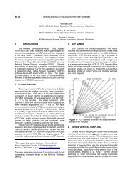
the actual Doppler velocity and the best fit function on an orthogonal axis of speed versus azimuth.<br />
The vertical axis presented shall be speed, scaled as necessary, to allow all data to be displayed. The<br />
Nyquist velocity for the specific scan shall be graphically annotated on the display if the range of the<br />
scaled vertical axis is sufficient. The horizontal axis shall be azimuth, scaled from 0-360 degrees<br />
with true North as 0/360 degrees. This product shall be available for any wind value included in the<br />
most recent time-height cross-section of the VAD Winds Product. This version of the product shall<br />
include annotations for the product name, radar ID, radar position, radar elevation above MSL, time<br />
and date of volume scan, slant range, elevation angle, wind speed and direction, computed altitude of<br />
winds, RMS error, and best fit function in the form A1 + V sin (θ+δ). (See Algorithm Report.)"<br />
12.2 Display Format<br />
The VWP is displayable in grid Format IVA, Appendix B. The grid is considered to be part of the<br />
image and will always be displayed simultaneously with the image.<br />
The grid for the VWP will consist of a vertical scale for altitude in thousands of feet above MSL and a<br />
horizontal time scale. The specific altitude levels are site adaptable. The vertical grid scale for the<br />
heights will be divided to equally space the number of heights that are selected. It will not be<br />
necessarily scaled since the screen is not large enough to accommodate the total interval that is<br />
possible to select. The adaptation data may have intervals of varying increments of 1,000. The<br />
horizontal time scale will accommodate up to 10 previous user selectable height plots (e.g., the last<br />
10 volume scans in addition to the current volume scan).<br />
12-1
The altitude levels will be indicated in thousands of feet along the right and left ordinates and the<br />
time (hour and minutes) along the abscissa. Full screen display will be used for this product. Wind<br />
barb units will be in knots. Direction in both cases will be the direction from which the wind is<br />
blowing in degrees.<br />
The VAD product is displayable in grid Format IVB, Appendix B. The grid is considered to be part of<br />
the image and will be displayed simultaneously with the image. In addition, the Nyquist Velocity for<br />
the specified scan will be graphically annotated on the display if it falls within the range of the<br />
scaled vertical axis.<br />
The grid for the VAD product consists of a vertical scale for velocity and a horizontal scale for<br />
azimuth. The equation for the FIT function in the form of A1 + V sin (Aε +δ) will also be displayed.<br />
The vertical scale is labeled with velocity values scaled such that all the data fits on the display. The<br />
unit for the velocity grid is knots. The horizontal scale is labeled with azimuth in 0 to 360 degrees.<br />
True North is 0/360 degrees. The FIT function is defined as above, where A1, V and δ corresponds to<br />
CF1, SPW and -DW-90 as defined in the <strong>NEXRAD</strong> Algorithm Report.<br />
The velocity values will be plotted as individual points on the orthogonal axis and overlaid with the<br />
best fit sine wave function.<br />
12.2.1 Data Levels<br />
For the VWP product, the wind vector flag shaft origin will be plotted to the appropriate elevation<br />
(ordinate) and time (abscissa) intersection.<br />
The wind vector will be plotted at the height at which it was observed. If the wind is calm, i.e.,<br />
sufficient echoes are present but velocities are
The color level table for the VAD product:<br />
The velocity points will be color coded to the reflectivity value at the same position. The eight-level<br />
color table is defined as follows:<br />
8-Level<br />
Code<br />
Display<br />
dBZ<br />
Range<br />
dBZ<br />
Color Levels<br />
Code<br />
Color<br />
(00 00 00) black<br />
0 Not Used<br />
1 dBZ (77 77 90) medium gray<br />
2 5 5
12.3 Annotations<br />
12.3.1 Alphanumeric<br />
For the VWP Product:<br />
Standard Annotations (Appendix A, I(A))<br />
Data Level Code<br />
Maximum Wind Speed (current plot)<br />
Direction of Wind Speed (current plot)<br />
Site Adaptable Parameters<br />
For the VAD Product:<br />
Standard Annotations (Appendix A, I(A))<br />
Slant Range<br />
Elevation Angle<br />
Wind Speed and Direction<br />
Root Mean Square (RMS) Error<br />
Computed Altitude of Wind<br />
12.3.2 <strong>Spec</strong>ial Symbols<br />
For the VWP Product:<br />
The wind speed and direction will be plotted with the standard meteorological wind barb<br />
presentation. The direction will be plotted as a straight line of 20 pixels in length from the direction<br />
of the wind. The vector will terminate at the intersection of the appropriate altitude and time.<br />
Wind direction is plotted to the nearest 5 degrees and speed to the nearest 5 knots. The special<br />
symbol for the wind barbs is a flag consisting of lines which are perpendicular and to the left of the<br />
wind shaft using the scale as indicated.<br />
2 barb (5 pixels in length) = 5 knots, example: 270° 65 kts<br />
1 barb (10 pixels in length) = 10 knots<br />
Full triangle (10 pixels in length and 4 pixel base) = 50 knots<br />
Shaft length = 20 pixels<br />
For the VAD Product:<br />
The velocity data will be plotted as single points on the grid of velocity vs. azimuth. The best fit<br />
function will be plotted over the field of velocity points as a linked vector in a contrasting color.<br />
The span of velocity data displayed on the grid is as follows:<br />
Velocity Span of Velocity data (grid)<br />
12.5 Comment<br />
All site adaptable parameters identified as input used to generate data for this product will be<br />
available at the alphanumeric display upon user request. This data will be formatted in tabular<br />
layout showing the parameter name in one column, and value in an adjacent column.<br />
12-5
13 DELETED<br />
13-1
14 CROSS SECTION (RCS, VCS)<br />
14.1 SS Product Description<br />
"This product shall provide a vertical cross section of reflectivity or mean radial velocity data<br />
displayable as an image for a user selected vector. This vector shall be defined by the operator using<br />
two end-points, up to 230 km apart, and at any orientation and location within 230 km of the radar.<br />
This product shall be produced by mapping the nearest value in range along a radial, to a point in<br />
the plane of the vertical cross section defined by the intersection of the plane and the radial. The<br />
displayable version of the product shall be produced by linearly interpolating between the mapped<br />
values, both horizontally and vertically as necessary. The product shall be generated only on<br />
request. The product shall be available for both 8 and 16 data levels defining the intensity range<br />
and velocity range data levels. The product shall include annotations for the product name, radar<br />
ID, time and date of volume scan, maximum data value and location(s), radar position, radar<br />
elevation above MSL, and the radar operational mode. The location of the vector center and the end<br />
points (az/ran) shall also be indicated."<br />
14.2 Display Format<br />
The product is displayable on a unique grid (Format V, Appendix B) with height as ordinate and the<br />
distance along the cross section as the abscissa. The distance grid scale of the abscissa will be one of<br />
three with the range of the data determining which grid scale is used. The three scales are 0 to 50<br />
nmi, 0 to 80 nmi, and 0 to 120 nmi. Range marks are labeled every 5 nmi for the 0 to 50 nmi range<br />
and every 10 nmi for the remainder.<br />
The origin of the grid represents the Western nearest or Northern end point of the vector, depending<br />
upon its orientation, and the data that is contained in the label of the grid is the range from the<br />
radar of this point. Vectors will be plotted to outline the cross section area. These vectors will show<br />
the extent of the data domain that is limited because of the length of the user supplied vector, and<br />
these outline vectors will also show the difference between the area of no data versus no radar<br />
sampled data.<br />
The grid is considered an integral part of the product and will always be available simultaneously<br />
with the image.<br />
14.2.1 Data Levels<br />
The data level values that may be selected for reflectivity and mean radial velocity are the same as<br />
those specified in 1.2.1 and 2.2.1, respectively.<br />
14.2.2 Color Level Code Tables<br />
The color level code table for the Reflectivity will be the 16-level table defined in 1.2.2. The Velocity<br />
table will be the 16-level velocity table defined in 2.2.2. The grid color will be light gray.<br />
14.2.3 Range/Data Resolution<br />
Coverage Area<br />
(R-Z plane)<br />
Resolution<br />
(nmi x nmi)<br />
Product <strong>Center</strong><br />
124 nmi x 70 kft Altitude 0.54 nmi Horizontal x 0.27 nmi Vertical N/A<br />
14.3 Annotations<br />
14.3.1 Alphanumeric<br />
Standard Annotations (Appendix A, I(A))<br />
14-1
Maximum Data Value Detected<br />
Location of Maximum Data Values<br />
Location of Vector <strong>Center</strong> (AZRAN)<br />
Location of Vector End Points (AZRAN)<br />
Data Level Codes<br />
Base Data Type<br />
14.3.2 <strong>Spec</strong>ial Symbols<br />
None defined<br />
14.4 Product Interaction<br />
None<br />
14-2
15 DELETED<br />
15-1
16 STORM RELATIVE MEAN RADIAL VELOCITY (SRM, SRR)<br />
16.1 SS Product Description<br />
"This product shall provide mean radial velocity for: (a) a small geographic area centered upon or<br />
near an identified storm of interest with the storm motion removed, or (b) the entire area of radar<br />
coverage (to 230 km) with the average storm motion removed. This product shall be produced upon<br />
request for any azimuth scan at any elevation angle. The product shall be generated as a<br />
displayable image by removing the radial (velocity component away from the radar antenna)<br />
component of storm motion from the mean radial velocity values.<br />
The radial component of storm motion shall be computed using the storm motion value computed for<br />
the identified storm by the Storm Cell Tracking Algorithm, the vector average of all currently<br />
identified storms or a value input by the user. The value of storm motion used to adjust the mean<br />
radial velocity values shall be user selectable at the time of product request, or default to the vector<br />
average of all currently identified storms if not selected. Each product shall contain 16 data levels<br />
for storm-adjusted mean radial velocity. Each product shall include annotations for the product<br />
name, radar ID, time and date of scan, elevation angle, storm motion, coordinates of product center,<br />
radar position, radar elevation above MSL, and radar operational mode."<br />
16.2 Display Format<br />
Each product version is displayable in full- or quarter-screen format (see Appendix B).<br />
16.2.1 Data Levels<br />
Both product versions use 16 data levels. The data level code may vary with operational mode and<br />
with <strong>NEXRAD</strong> (or agency) system adaptation data. One currently identified velocity table is shown.<br />
16.2.2 Color Level Code Tables<br />
Color Levels<br />
16-Level<br />
Code<br />
Display<br />
knots<br />
Range<br />
knots Code Color<br />
0 ND SNRknots (00 E0 FF) light blue<br />
2 -40 -40>knots>-50 (00 80 FF) medium blue<br />
3 -30 -30>knots>-40 (32 00 96) dark blue<br />
4 -22 -22>knots>-30 (00 FB 90) light green<br />
5 -10 -10>knots>-22 (00 BB 00) medium green<br />
6 -5 -5>knots>-10 (00 8F 00) dark green<br />
7 -1 0>knots>-5 (CD C0 9F) light gray<br />
8 0 0
Version (a) 27 x 27 (Region) 0.27x1 Location of storm center<br />
Version (b) 0 to 124 (Map) 0.54x1 <strong>Radar</strong> location<br />
16.3 Annotations<br />
16.3.1 Alphanumeric<br />
Standard Annotations (Appendix A, I(A))<br />
Elevation Angle<br />
Coordinates of Product <strong>Center</strong> (AZRAN or Lat/Long)<br />
Data Level Code<br />
Maximum Data Values Detected (after storm motion removal)<br />
Motion Vector*<br />
Height Above Ground level of the Window Containing the Meteorological Phenomena**<br />
16.3.2 <strong>Spec</strong>ial Symbols<br />
None defined<br />
16.4 Product Interaction<br />
All overlay products are displayable on this product:<br />
Hail Index<br />
Mesocyclone<br />
Storm Tracking Information<br />
Tornado Vortex Signature.<br />
- - - - - - -<br />
*Either a mean for all storms (map), or for one particular storm (region) derived from storm series<br />
algorithms or as operator input.<br />
16-2
17 VERTICALLY INTEGRATED LIQUID (VIL)<br />
17.1 SS Product Description<br />
"This product shall provide vertically integrated liquid values displayed as an image. The output of<br />
the VIL Algorithm shall be used to produce this product. The product shall be updated once per<br />
volume scan time. The product shall be available for 16 data levels. Each product shall include<br />
annotations for product name, radar ID, time and date of volume scan, maximum data value (VIL<br />
value,), radar position, radar elevation above MSL, and the radar operational mode.'<br />
17.2 Display Format<br />
The product is displayable in full- or quarter-screen format (see Appendix B).<br />
17.2.1 Data Levels<br />
The VIL values displayed range upwards to a maximum adaptable value (default = 80 Kg/m 2 ).<br />
Values greater than that value are truncated to that value.<br />
17.2.2 Color Level Code Tables<br />
The color level code used for display of VIL is a <strong>NEXRAD</strong> (or agency) system adaptation data. The<br />
currently defined color table for VIL is listed.<br />
Color Levels<br />
16-Level<br />
Code<br />
Display<br />
kg m -2<br />
Range<br />
kg m -2 Code Color<br />
0 ND kg m -2
17.3 Annotations<br />
17.3.1 Alphanumeric<br />
The automated annotations for this product are:<br />
Standard Annotations (Appendix A, I(A))<br />
Data Level Code<br />
Maximum Data Value Detected<br />
17.3.2 <strong>Spec</strong>ial Symbols<br />
None defined<br />
17.4 Product Interaction<br />
All overlay products are displayable on this product:<br />
Hail Index<br />
Mesocyclone<br />
Storm Tracking Information<br />
Tornado Vortex Signature.<br />
17-2
18 STORM TRACKING INFORMATION (STI)<br />
18.1 SS Product Description<br />
"This product shall provide information concerning the past, present and future positions of each<br />
identified storm cell. This product shall be generated from the output of the Storm Cell Tracking<br />
and Storm Position Forecast algorithms. It shall be produced in a tabular format of alphanumeric<br />
values, as a stand alone graphic product, and in a format for generating graphic overlays to other<br />
products. This product shall be updated once per volume scan time. Each product shall include a<br />
standard set of total annotations and number of identified storm cells for which tracking is available.<br />
Upon user request, all site adaptable parameters identified as inputs to the algorithm(s) used to<br />
generate data for this product shall be available at the alphanumeric display."<br />
18.2 Display Format<br />
Each storm cell identified will be given a unique ID of two characters. The first character will be a<br />
capital letter, A through Z, and the second will be a number, 0 through 9. The sequence will be A0,<br />
B0, C0,...Z0, A1,...Z9. The sequence is recycled following Z9. When there have not been any storm<br />
cells identified in a user specified "number of past volume scans", then the sequence of IDs will be<br />
reset so that the next storm cell identified will have the ID A0. See also Appendix A, I(B)(21) for<br />
more details on the Storm Cell ID.<br />
18.2.1 Graphic Display<br />
The product is displayable in full- and quarter-screen formats (see Appendix B, Formats I and II).<br />
18.2.1.1 Data Display<br />
The ID will be placed 5 pixels to the right and 5 pixels down from the current centroid positions. The<br />
ID will be white (code FF FF FF) and the background in black (code 00 00 00). See also Appendix A,<br />
I(B)(2).<br />
When sufficient data is available, the past positions for each volume scan (up to the number of past<br />
volume scan minus the current volume scan) will be shown along with the current position and up to<br />
four future positions (e.g., +15, +30, +45, +60 min).<br />
The forecast position interval and number of past volumes (or positions) are Unit <strong>Radar</strong> Committee<br />
(URC) level adaptation data and will vary over a range of 5 to 60 minutes (in 5-minute increments)<br />
and 5 to 13 volume scans, respectively. The default interval is 15 minutes, and the default number<br />
of past volumes (or positions) is 10. The past positions displayed will be the actual centroid positions<br />
where each storm cell was identified for up to the specified number of past volume scans (including<br />
the current volume scan). Storm cell tracks will consist of past, current and forecast storm cell<br />
centroid positions connected by one pixel wide linear segments. The PUP operator will have the<br />
ability through a menu at the Alphanumeric Terminal to select whether to display the past and/or<br />
forecast tracks and positions.<br />
In the event an identified storm cell's forecast speed is less than a user-specified minimum speed, the<br />
storm cell's motion is considered stationary. For stationary storm cells, no past or forecast storm cell<br />
positions will be displayed. The minimum storm cell speed is URC level adaptation data and will<br />
vary over the range of 0.0 m/s to 10.0 m/s. The default is 2.5 m/s.<br />
Note: See "<strong>Spec</strong>ial Symbols and Characters" of Appendix A, 1(B(2)) for more details on the Storm<br />
Cell Track<br />
The PUP operator will have the ability through a one level password protected menu at the<br />
Alphanumeric Terminal to select a maximum number of storm cells for display within the current<br />
18-1
display area (or window). The default is 20 storm cells. When the number of identified storm cells in<br />
the current window exceeds the maximum number of cells for display, the storm cells with the<br />
largest Cell-based VIL will be selected for display and a message will be displayed in the lower left<br />
corner of the screen indicating the number of identified storm cells in the current window which are<br />
not displayed. The message will have the same format as in the following example: "4 CELLS IN<br />
WINDOW NOT DISPLAYED". If the number of storm cells not displayed in the current window<br />
changes, the message will change as well.<br />
18.2.1.2 Range/Data Resolution<br />
Coverage Area<br />
(nmi radius)<br />
Resolution<br />
(nmi x nmi) Product <strong>Center</strong><br />
0 to 248 N/A <strong>Radar</strong> location<br />
18.2.1.3 Graphic Overlay<br />
As a graphic overlay to other products, only the overlay portion of the graphic display product is<br />
displayed; that is, the screen right annotations are not displayed. Symbols and characters are<br />
described in the data display above.<br />
18.2.2 Alphanumeric Display<br />
18.2.2.1 Alphanumeric Screen<br />
A tabular format (Appendix C) of up to an adaptable number of identified storms cells will be<br />
displayable on the alphanumeric display screens. The tabular format will include:<br />
(a) Storm Cell ID<br />
(b) Current storm Position in (AZRAN) degrees and nmi to the nearest integer from the RDA<br />
(c) The Forecast Direction in degrees (to the nearest integer) from which the storm cell is moving<br />
(d) The Forecast Speed of the storm cell in kts to the nearest integer<br />
(e) The azimuth and range forecast position of the storm cell to the nearest integer in degrees and<br />
nmi for each forecast interval up to four forecast positions<br />
(f) The forecast error and mean forecast error in nmi to the nearest 0.1 nmi<br />
(g) On the first page, Average Storm Cell Speed in kts to the nearest integer<br />
(h) On the first page, Average Storm Cell Direction in degrees to the nearest integer<br />
(i) Storm Cell Tracking/Forecast Position Adaptable Parameters<br />
By default, all storm cells (entries), up to a maximum of 100, can be displayed in this format.<br />
However, the MSCF has the capability to limit the number of storm cells included in this format<br />
from 7 to 100.<br />
Note: Storm cells which are new (i.e., lack history) shall indicate "NEW" in the Movement field.<br />
Note: If a forecast position(s) for a storm cell can not be determined, then "NO DATA" shall be<br />
displayed for that interval in the Forecast Positions field of the alphanumeric display.<br />
18-2
18.2.2.2 Graphic Screen<br />
A tabular format (appendix B, Format III, configuration 1) of all identified storm cells will be<br />
displayable on the graphic display screens. The tabular format will include:<br />
(a) Storm Cell ID<br />
(b) Current Storm Position in (AZRAN) degrees and nmi to the nearest integer form the RDA<br />
(c) The Forecast Direction in degrees to the nearest integer form which the storm cell is moving<br />
(d) The Forecast Speed of the storm cell in kts to the nearest integer<br />
(e) The forecast error and mean forecast error in nmi to the nearest 0.1 nmi<br />
(f) Maximum reflectivity in dBZ to the nearest integer<br />
(g) Height of the Maximum Reflectivity in kft to the nearest integer<br />
Note: Storm cells which are new (i.e., lack history) shall indicate "NEW" in the Forecast Movement<br />
field.<br />
18.3 Annotations<br />
18.3.1 Alphanumeric<br />
Standard Annotations<br />
Total Number of Identified Storms<br />
18.3.2 <strong>Spec</strong>ial Symbols<br />
Past positions of the storm will be shown as small (5-pixel diameter) white, filled circles and forecast<br />
positions as white plus (+) marks of similar size. The current position is a circle (7-pixel diameter)<br />
within which is an "X".<br />
The past, current, and forecast position symbols are connected with white line segments.<br />
18.4 Product Interaction<br />
The graphic portion of the product including the tabular format is displayable as an overlay on all<br />
geographically based products.<br />
18.5 Comments<br />
All site Storm Cell Tracking/Forecast adaptable parameters identified as inputs to generate data for<br />
this product will be available at the alphanumeric display upon user request. This data will be<br />
formatted in a tabular layout showing the parameter name in one column and the value in an<br />
adjacent column.<br />
18-3
19 HAIL INDEX (HI)<br />
19.1 SS Description<br />
"This product shall provide, for each storm cell identified by the Storm Cell Identification and<br />
Tracking algorithm, the Probability of Hail, the Probability of Severe Hail, and the Maximum<br />
Expected Hail Size. The hail probabilities and size shown for each storm cell shall be generated by<br />
the Hail Algorithm. This product shall be produced in a tabular format of alphanumeric values, as a<br />
stand alone graphic product, and in a format for generating graphic overlays to other products. This<br />
product shall include a standard set of annotations. Upon user request, all site adaptable<br />
parameters identified as inputs to the algorithm(s) used to generate data for this product shall be<br />
available at the alphanumeric display."<br />
19.2 Display Format<br />
The Probabilities of Hail and Severe Hail are computed in 10% increments. The Maximum Expected<br />
Hail Size is calculated to the nearest 0.25 inch.<br />
19.2.1 Graphic Display<br />
The product is displayable in full- or quarter-screen formats (See Appendix B, Formats I and II).<br />
19.2.1.1 Data Display<br />
If the Probability of Hail and/or the Probability of Severe Hail for a storm cell meet minimum display<br />
adaptable parameters, then a Hail Symbol (see Appendix A, I(A)(6) is placed immediately to the<br />
right of the storm cell ID. That position will be 19 pixels to the right and 2 pixels down form the<br />
storm cell centroid location. As a graphic overlay to other products, the hail symbol flashes and only<br />
the overlay portion of this product are displayed. The operator has the option to stop the flashing of<br />
the hail symbol. No hail symbol is displayed if the Probability of Severe Hail and the Probability of<br />
Hail are 0%.<br />
The Maximum Expected Hail Size is also displayed in the middle of the Hail Symbol in white to the<br />
nearest inch. In this display, if the Maximum Expected Hail Size is less than 0.75 inches, an<br />
asterisk will be displayed, and if the size is greater than 4 inches, "4" inches will be displayed.<br />
19.2.1.2 Range/Data Resolution<br />
Coverage Area<br />
(nmi radius)<br />
Resolution<br />
(nmi x deg) Product <strong>Center</strong><br />
0 to 124 N/A N/A<br />
19.2.1.3 Graphic Overlay<br />
As a graphic overlay to other products, only the overlay portion of the graphic display product and<br />
the attribute table is displayed.<br />
19.2.2 Alphanumeric<br />
19.2.2.1 Alphanumeric Display<br />
In the alphanumeric product (tabular format for the alphanumeric screen), the Hail Attribute Table<br />
(see Appendix B, format III, configuration 4), and the combined Attribute Table (see Appendix B,<br />
Format III, configuration 5), the following apply: if the Probability of Severe Hail and the Probability<br />
of Hail are 0%, then "0.00" inches is displayed; if the Probability of Severe Hail and the Probability of<br />
Hail ore greater than 0% and the Maximum Expected Hail Size is less than 0.50 inches, then "
">4.00" inches is displayed; if the hail characteristics can not be determined (e.g. storm cell is beyond<br />
124 nmi range) the hail characteristics are labeled 'UNKNOWN'.<br />
By default, all storm cells (entries), up to a maximum of 100, can be displayed in this format.<br />
However, the MSCF has the capability to limit the number of storm cells included in this format<br />
from 10 to 100.<br />
19.2.2.2 Alphanumeric Screen<br />
The tabular format, displayed on the alphanumeric screen (i.e. the Hail alphanumeric product),<br />
includes up to an adaptable number of storm cells identified by the Storm Cell Centroids Algorithm.<br />
The format used is specified in Appendix C.<br />
(a) Storm Cell ID<br />
(b) Probability of Severe Hail in percentage<br />
(c) Probability of Hail in percentage<br />
(d) Maximum Expected Hail Size in inches<br />
(e) Adaptable Hail Parameters<br />
19.2.2.3 Graphic Screen<br />
The tabular format, displayed on the graphic screen (i.e. the Hail Attribute Table) includes all storm<br />
cells identified by the Storm Cell Centroids Algorithm. The format used is specified in Appendix B,<br />
Format III, Configuration 4.<br />
(a) Storm Cell ID<br />
(b) Current Storm Position in (AZRAN) degrees and nmi to the nearest integer from the RDA<br />
(c) Probability of Severe Hail in percentage<br />
(d) Probability of hail in percentage<br />
(e) Maximum Expected hail Size in inches<br />
(f) Altitude of 0°C and -20°C environmental temperatures in kft (from adaptation data)<br />
(g) Time and Date of the last change to the Hail Temperature Altitudes<br />
19.3 Annotations<br />
19.3.1 Alphanumeric<br />
Standard Annotations (Appendix A, I(A))<br />
19.3.2 <strong>Spec</strong>ial Symbols<br />
The hail symbol is a green isosceles triangle. The triangle can be small (a base of 8 pixels and a<br />
height of 12 pixels) or large ( a base of 16 pixels and a height of 20 pixels). The size of the triangle<br />
and whether the triangle is filled depends upon the Probability of Severe Hail and the Probability of<br />
Hail. The following are the rules of display and default settings.<br />
Triangle Prob. Of Svr. Hail Prob. Of Hail<br />
Large/Filled >50% N/A<br />
Large/Open >30% N/A<br />
Small/Filled 0% >50%<br />
Small/Open 0% >30%<br />
However, the probabilities are adaptable parameters at the PUP alphanumeric terminal, and the<br />
user has the ability to disable the display of one or both of the small and/or large triangles. The<br />
Maximum Expected Hail Size will be displayed in the middle of the triangle.<br />
19-2
19.4 Product Interaction<br />
The graphic portion of the product including the tabular format is displayable as an overlay to all<br />
geographically based products.<br />
19.5 Comments<br />
All site adaptable parameters identified as inputs to generate data for this product will be available<br />
at the alphanumeric display upon user request. This data will be formatted in a tabular layout<br />
showing the parameter name in one column and the value in an adjacent column.<br />
When ranking of storm cells by hail characteristics, storm cells labeled 'UNKNOWN' are considered<br />
of lower rank than those with a Probability of Severe Hail of 0% and a Probability of Hail of 0%.<br />
19-3
20 MESOCYCLONE (M, MRU, MD, DMD)<br />
20.1 SS Product Description<br />
"The Mesocyclone (M) product shall provide information about identified shear and mesocyclone<br />
features. This product shall be generated from the output of the Legacy Mesocyclone Detection<br />
Algorithm. This product shall be generated in a format that can be used to generate an<br />
alphanumeric tabular display for an identified feature or all simultaneously, a graphic display or a<br />
graphic overlay to other products. This product shall be updated once per volume scan time. If on a<br />
particular volume scan there is no output from the Legacy Mesocyclone Detection Algorithm (i.e., no<br />
features of any type are identified), a version of the product shall be produced that exhibits the<br />
negative condition. This product shall include annotations for the product name, radar ID, date and<br />
time of volume scan, radar position, radar elevation above MSL, and radar operational mode. Upon<br />
user request, all site adaptable parameters identified as input to the algorithm(s) used to generate<br />
data for this product shall be available at the alphanumeric display."<br />
“A Mesocyclone Rapid Update (MRU) version of this product shall be generated once per elevation<br />
scan time to provide updated Legacy Mesocyclone Detection Algorithm information. Current Legacy<br />
Mesocyclone Algorithm data at an elevation scan shall be based on the elevations that have been<br />
completed thus far in the current volume scan. This information shall be combined with<br />
Mesocyclone and Storm Track Algorithm information from the previous volume scan to form the<br />
MRU product.<br />
The average motion of all SCIT storm cells from the previous volume scan shall be used to derive a<br />
forecast position of each previous feature at the current volume scan time. In feature type order, the<br />
forecast position of each feature from the previous volume scan shall be matched to the closest<br />
feature from the current volume scan, within a search radius defined by SCIT algorithm adaptation<br />
data. Current 3D features which are not matched to a feature from the previous volume scan, shall<br />
be assigned the status of New. If previous volume scan data are unavailable, all features shall be<br />
reported as new. Current features shall inherit the attributes of the matched previous feature<br />
(associated storm ID, feature type, maximum tangential shear, height of maximum tangential shear,<br />
top height, base azimuth, base range, base height, azimuth diameter, range diameter).<br />
The position attributes (base azimuth, range, and height) of a previous feature matched to a current<br />
feature shall be updated to the current detection. If the top height of the matched feature is higher,<br />
the feature top height shall be updated. The position attributes of a previous feature not matched to<br />
a current feature, shall be set to the extrapolated forecast position. The status of unmatched<br />
previous features shall be assigned to Extrapolated. Strength attributes shall be updated if they<br />
increase in magnitude.<br />
The strength attributes are feature type and maximum tangential shear. If the maximum tangential<br />
shear is updated, the radial and azimuthal diameters and the height of the maximum tangential<br />
shear shall also be updated. Features with increasing strength attributes shall be assigned the<br />
status of Increasing. All other matched features shall be assigned the status of Persistent. Attribute<br />
data updated with current volume data shall be identified. At the end of the volume scan<br />
extrapolated features shall be removed.<br />
This product shall be generated in a format that can be used to generate an alphanumeric tabular<br />
display, a graphic display or a graphic overlay to other products. On alphanumeric displays, the<br />
status (Persistent, Increasing, New, or Extrapolated) of each feature status shall be reported. In the<br />
graphic symbol display, features status shall be reported as either extrapolated or current. Current<br />
features include all features with a status of Increasing, Persistent, or New. If on a particular<br />
elevation scan there is no output (i.e., no features of any type are identified), a version of the product<br />
20-1
shall be produced that exhibits the negative condition. This product shall include annotations for<br />
the product name, radar ID, date and time of volume scan, elevation angle, radar position, radar<br />
elevation above MSL, and radar operational mode.”<br />
"The MD version of this product shall provide information about circulation features generated from<br />
the output of the new Mesocyclone Detection Algorithm. This product shall provide information<br />
concerning the past and future positions of each tracked circulation feature. This product shall be<br />
generated in a format that can be used to generate an alphanumeric tabular display for an identified<br />
feature or all simultaneously, a graphic display or a graphic overlay to other products. This product<br />
shall be updated once per volume scan time. If on a particular volume scan there is no output from<br />
the Mesocyclone Detection Algorithm (i.e., no features of any type are identified), a version of the<br />
product shall be produced that exhibits the negative condition. This product shall include<br />
annotations for the product name, radar ID, date and time of volume scan, radar position, radar<br />
elevation above MSL, and radar operational mode."<br />
The DMD version of this product shall be generated to support generation of interactive user<br />
displays at an external system (e.g., AWIPS). This product shall be updated once per elevation scan<br />
time. The end-of-volume edition shall contain complete algorithm data for the volume scan. The<br />
elevation editions shall contain the algorithm data which has been updated since the previous<br />
volume edition product. A detection status shall be reported for circulation features that are topped<br />
or extrapolated. If on a particular elevation scan there is no output from the Mesocyclone Detection<br />
Algorithm (i.e., no features of any type are identified), a version of the product shall be produced that<br />
exhibits the negative condition. This product shall include annotations for the product name, radar<br />
ID, date and time of volume scan, elevation angle, radar position, radar elevation above MSL, and<br />
radar operational mode.<br />
20.2 Display Format<br />
20.2.1 Graphic Display<br />
The products are displayable in full- or quarter-screen format (see Appendix C).<br />
20.2.1.1 Data Display<br />
The mesocyclone or 3D correlated shear symbol will be placed directly over the position of the<br />
mesocyclone or shear at the lowest elevation scan in which it was detected. For the MRU product:<br />
extrapolated mesocyclone and 3D correlated shear features will be displayed centered on the<br />
forecasted position at the lowest elevation scan it was previously detected; mesocyclone and 3D<br />
correlated shear features detected in the current volume scan will be displayed centered on the<br />
position of the matched current feature at the lowest angle in which it is detected. See also<br />
Appendix A, I(B)(4).<br />
For the MD version, the graphic display will contain up to 100 MDA detected features, sorted first by<br />
strength rank, then by Mesocyclone Strength Index (MSI). The number of features in the product<br />
can be reduced by raising the minimum display filter rank and/or the overlap filter, both MDA<br />
adaptable parameters.<br />
When sufficient data are available, the past positions of each feature for each volume scan (up to 10<br />
past volume scans) will be shown along with the current position and up to six future positions (at 5<br />
minute intervals). The past positions will be displayed at the lowest elevation each MDA feature<br />
was detected. MDA tracks will consist of past, current and forecast positions connected by linear<br />
segments with a width of one pixel. The operator at the external display system (e.g., AWIPS) will<br />
have the ability to select whether to display the past and/or forecast tracks and positions and feature<br />
IDs.<br />
20-2
In the event an identified MDA feature forecast speed is less than 2.5 m/s the feature motion is<br />
considered stationary. For stationary MDA features, a single past position will be reported at the<br />
current feature center.<br />
20.2.1.2 Range/Data Resolution<br />
Coverage Area Resolution (nmi Product <strong>Center</strong><br />
(nmi radius)<br />
x nmi)<br />
0 to 124 N/A <strong>Radar</strong> location<br />
20.2.1.3 Graphic Overlay<br />
As a graphic overlay to other products, it will be possible to display only the image portion of this<br />
product; that is, the screen right area annotations will not be displayed when the product is used as<br />
an overlay. Each mesocyclone will be identified with the associated storm ID in white. In overlay<br />
form, the mesocyclone and 3D shear symbol have pixel priority over all but the TVS symbol. The<br />
mesocyclone and 3D shear symbols, which are displayed in yellow, flash when displayed as overlays.<br />
The operator will have the option to stop the flashing of the mesocyclone symbol.<br />
For the MRU version, the AWIPS operator will have the option to turn off display of extrapolated<br />
features.<br />
For the MD version, circulations strong enough to be classified as mesocyclones will be identified<br />
with the Circulation ID (0 to 999) displayed next to the mesocyclone symbol.<br />
20.2.2 Alphanumeric Display<br />
An alphanumeric tabular product version is generated for display on the alphanumeric display. The<br />
format to be used is defined in Appendix C.<br />
With the following exceptions, the format of the MRU graphic attribute and alphanumeric tabular<br />
portions of the product will follow the non-rapid update Mesocyclone product: feature status will be<br />
reported as EXT, PER, INC, and, NEW to denote extrapolated, persistent, increasing, and new<br />
features, respectively; and the character ^ (hexadecimal value 5E) will be placed next to data which<br />
was computed from current volume scan detections. The format to be used is defined in Appendix B<br />
and C.<br />
For the MD version, up to 100 features will be listed from highest to lowest strength rank with<br />
Mesocyclone Strength Index (MSI) as a secondary order (highest MSI to lowest MSI).<br />
Except for those parameters indicated with an asterisk above, the elevation edition will contain only<br />
parameters updated since the previous volume. A complete time history of MDA information for a<br />
feature is available from a collection of DMD volume editions along with the latest DMD elevation<br />
edition. All data for an on-going feature can be linked by its Meso ID parameter that remains<br />
constant through out the life time of a feature.<br />
If the base is detected on the lowest elevation scan of the volume scan, then the BASE (height) is<br />
qualified with ‘’.<br />
20.2.3 DMD Format for External Systems<br />
The DMD product is a rapid update implementation of the MDA, meaning that after each elevation<br />
cut of the current volume scan, algorithm output is available to update any MDA results from the<br />
previous volume scan. Therefore, it is important to distinguish between products with the Last<br />
20-3
Elevation Flag set (i.e. a volume edition) and those without the Last Elevation Flag set (i.e. an<br />
elevation edition). A volume edition, will contain complete MDA information for the volume scan.<br />
For the volume edition, the parameters listed below are included for all detected MDA features<br />
meeting a minimum strength rank of 1 (up to a maximum of 100 features):<br />
As specified in Figure 3-15b, Note 1, of the RPG To Class 1 User ICD, the DMD product is encoded<br />
using an API available from the <strong>Radar</strong> <strong>Operations</strong> <strong>Center</strong>. This API also provides functions for<br />
those wishing to decode a DMD product, as well as extract product parameters and feature<br />
parameters. The DMD product contains up to 100 MDA detected circulation features. All DMD<br />
products contain the following three DMD Product Parameters:<br />
DMD Format for External Systems<br />
DMD Product<br />
Units ; Precision or<br />
Parameters<br />
Values<br />
(One parameter per DMD<br />
product)<br />
Average Direction of deg ; 0.1<br />
Tracked Features<br />
Average Speed of Tracked m/s ; 0.1<br />
Features<br />
Last Elevation Flag<br />
Elevation Angle (array) deg ; 0.1<br />
Elevation Time (array) s ; 1<br />
MDA Feature<br />
Parameters<br />
(One parameter per MDA<br />
detected circulation)<br />
Values = 0 or 1 if last<br />
elevation<br />
Units ; Precision or<br />
Values<br />
Meso ID (1) na ; 1<br />
Detection Status (1) Values = "TOP", "EXT", “<br />
“<br />
Base Azimuth (1) deg ; 0.1<br />
Base Range (1) km ; 0.1<br />
Age s ; 1<br />
Strength Rank na ; 1<br />
Strength Rank Type Values = ' ', 'L' or 'S' (2)<br />
MSI na ; 1<br />
Base Diameter km ; 0.1<br />
Base Height km ; 0.1<br />
Depth km ; 0.1<br />
Storm Relative Depth percent ; 1<br />
Base Gate-to-Gate Velocity m/s ; 0.1<br />
Difference<br />
Base Shear m/s/km ; 0.1<br />
Base Rotational Velocity m/s ; 0,1<br />
Max Rotational Velocity m/s ; 0.1<br />
Height of Max Rotational km ; 0.1<br />
Velocity<br />
Max Shear m/s/km ; 0.1<br />
Height of Max Shear km ; 0.1<br />
0-2 km ARL Convergence m/s ; 0.1<br />
20-4
2-4 km ARL Convergence m/s ; 0.1<br />
Associated TVS<br />
Values = 'Y', 'N' or 'U'<br />
Associated Storm ID Values = "A0" through "Z9"<br />
Overlaps Lower Feature Values = "Y" or "N"<br />
Base on Lowest Elevation Values = "Y" or "N"<br />
Direction deg ; 0.1<br />
Speed m/s ; 0.1<br />
# Past Positions na ; 1<br />
Past Latitude Position deg; 0.0001<br />
(array)<br />
Past Longitude Position deg; 0.0001<br />
(array)<br />
# Forecast Positions na ; 1<br />
Forecast Latitude Position deg; 0.0001<br />
(array)<br />
Forecast Longitude deg; 0.0001<br />
Position (array)<br />
Number of 2D Features in na ; 1<br />
this 3D Feature<br />
Tilt Number (array) na ; 1<br />
2D Height (array) km ; 0.1<br />
2D Diameter (array) km ; 1<br />
2D Gate-to-Gate Velocity m/s ; 1<br />
Difference (array)<br />
2D Shear (array) m/s/km ; 1<br />
2D Rotational Velocity m/s ; 1<br />
(array)<br />
2D Strength Rank (array) na ; 1<br />
(1) Always included for all features<br />
(2) L = Low core. This means the "core depth" must be LESS THAN 3 km AND the core depth must<br />
be GREATER THAN 25% of the mean SCIT cell depth AND the core base must be LESS THAN<br />
3km. S = Shallow. This means the "core depth" must be GREATER THAN 1 km AND the core top<br />
must be LESS THAN 3km AND the strength rank is GREATER THAN OR EQUAL TO 5.<br />
20.3 Annotations<br />
20.3.1 Alphanumeric<br />
Standard annotations<br />
Site Adaptable Parameters for the legacy version<br />
Elevation angle for the MRU version<br />
All annotations (except for <strong>Radar</strong> position) with the alphanumeric product format will be included in<br />
the message.<br />
20.3.2 <strong>Spec</strong>ial Symbols<br />
The mesocyclone will be displayed (centered on the location of the mesocyclone at the lowest<br />
elevation angle in which it is detected) as a yellow open circle, whose perimeter is 4 pixels thick. The<br />
size of the symbol will be proportional to the average of the mesocyclone radial and azimuthal<br />
diameters. The minimum size symbol will be a circle having a diameter of 14 pixels.<br />
The 3D correlated shear will be displayed as a yellow open circle, 1 pixel thick and is centered<br />
(similarly to the mesocyclone) on the 3D shear center at the lowest elevation angle at which it was<br />
20-5
detected. The size will be proportional to the average diameter. The minimum size symbol will be a<br />
circle having a diameter of 14 pixels.<br />
For the MRU version, AWIPS will distinguish between the Mesocyclone and 3D correlated shear<br />
features will by the thickness of the perimeter of a circle (i.e., thick perimeter is a Mesocyclone and<br />
thin for 3D Correlated Shear). In addition, AWIPS will distinguish between current (new,<br />
persistent, and increasing) and extrapolated (unmatched) 3D features by the line style of the circle<br />
perimeter (i.e., traditional AWIPS mesocyclone and 3D Correlated shear symbols are used for<br />
current features, but symbols with a dashed perimeter are used for extrapolated features).<br />
For the MD version, features having a strength rank 5 or higher will be displayed similar to the<br />
legacy Mesocyclone symbol. In addition, if the feature’s base was detected on the lowest elevation<br />
angle, or its base height was at or below 1 kilometer, the Mesocyclone symbol will contain outward<br />
spikes. For MDA features having a strength rank less than 5, the symbol will be similar to the<br />
legacy 3D correlated shear symbol. The size of the symbol will be drawn to scale with the base level<br />
feature diameter.<br />
The MDA track consists of past, current, and forecast feature positions connected by linear segments<br />
one pixel wide. Past positions will be displayed as yellow filled diamond. Forecast positions will be<br />
displayed as yellow x cross signs, of similar size.<br />
20.4 Product Interaction<br />
This product is displayable as an overlay on all geographically based products. For the MRU<br />
version, the AWIPS operator will be provided the option to choose between displaying the latest<br />
elevation (i.e., highest elevation) and displaying a specific elevation; when the latest elevation is<br />
selected, the display will automatically update when higher elevation products are received.<br />
20.5 Comments<br />
All site adaptable parameters identified as inputs to the algorithm used to generate data for this<br />
product will be available for display at the applications terminal upon user request. See 12.8 for the<br />
format description.<br />
The current value of the three MDA adaptable parameters will be placed in a corner of the graphic<br />
overlay display. If there are no features, the text “No Circulations” will be placed on the graphic<br />
display<br />
20-6
21 TORNADO VORTEX SIGNATURE (TVS)<br />
21.1 SS Product Description<br />
"This product shall provide information regarding the existence and location of an identified Tornado<br />
Vortex Signature (TVS). This product shall be produced from the output of the Tornado Detection<br />
Algorithm. The product shall produce an alphanumeric tabular display and a graphic overlay of the<br />
algorithm output data for each identified TVS (and Elevated TVS (ETVS)) signature information<br />
when such is identified. This product shall be updated once per volume scan time. This product<br />
shall include annotations for the product name, radar ID, time and date of volume scan, radar<br />
position, radar elevation above MSL, and radar operational mode. Upon user request, all site<br />
adaptable parameters identified as inputs to the algorithm(s) used to generate data for this product<br />
shall be available at the alphanumeric display."<br />
“A Tornado Vortex Signature Rapid Update (TRU) version of this product shall be generated once<br />
per elevation scan time to provide updated Tornado Detection Algorithm (TDA) information. Current<br />
Tornado Detection Algorithm data at an elevation scan shall be based on the elevations that have<br />
been completed thus far in the current volume scan. This information shall be combined with TDA,<br />
MDA, and Storm Track Algorithm information from the previous volume scan to form the TRU<br />
product.<br />
The average motion of all tracked MDA features from the previous volume scan shall be used to<br />
derive a forecast position of each TDA feature from the previous volume scan at the current volume<br />
scan time. If the average motion from MDA is unavailable, the average motion of all SCIT storm<br />
cells from the previous volume scan shall be used. In priority rank order, the forecast position of each<br />
feature from the previous volume scan shall be matched to the closest feature from the current<br />
volume scan, within a search radius defined by SCIT algorithm adaptation data.<br />
Priority rank order places TVS types before ETVSs, and within each type features are ordered by<br />
Low-level Delta Velocity, from greatest to least. Current TVS/ETVS features which are not matched<br />
to a feature from the previous volume scan, shall be assigned the status of New. If previous volume<br />
scan data are unavailable, all features shall be reported as New. Current features shall inherit the<br />
attributes of the matched previous feature (associated storm ID, feature type, low-level delta<br />
velocity, maximum delta velocity and its height, average delta velocity, maximum shear and its<br />
height, base and top heights, depth, and base azimuth and range).<br />
The position attributes (base azimuth, range, and height) of a previous feature matched to a current<br />
feature shall be updated to the current detection. The position attributes of a previous feature not<br />
matched to a current feature, shall be set to the extrapolated forecast position (base azimuth and<br />
range only). The status of unmatched previous features shall be assigned to Extrapolated.<br />
Strength attributes of a previous feature matched to a current feature shall be updated if they<br />
increase in magnitude. The strength attributes are feature type, low-level delta velocity, and depth.<br />
The attributes maximum delta velocity, maximum shear, and average delta velocity are also updated<br />
to the current value if they increase in magnitude, but their increase will not trigger a status change<br />
to Increasing. If the maximum delta velocity and maximum shear are updated, their heights shall<br />
also be updated. Features with increasing strength attributes shall be assigned the status of<br />
Increasing. All other matched features shall be assigned the status of Persistent.<br />
Attribute data updated from current volume data shall be identified. At the end of the volume scan,<br />
the extrapolated features shall be removed. This product shall be generated in a format that can be<br />
used to generate an alphanumeric tabular display, a graphic display or a graphic overlay to other<br />
products. In each type of display, features shall appear in priority rank order. On alphanumeric<br />
21-1
displays, the status (Persistent, Increasing, New, or Extrapolated) of each feature status shall be<br />
reported.<br />
In the graphic symbol display, features status shall be reported as either extrapolated or current.<br />
Current features include all features with a status of Increasing, Persistent, or New. If on a<br />
particular elevation scan there is no output (i.e., no features of any type are identified), a version of<br />
the product shall be produced that exhibits the negative condition. This product shall include<br />
annotations for the product name, radar ID, date and time of volume scan, elevation angle, radar<br />
position, radar elevation above MSL, and radar operational mode.”<br />
21.2 Display Format<br />
The product has three parts. Geographic and alphanumeric table parts are displayable on the<br />
graphic screen. And the alphanumeric table is displayable on the alphanumeric screen. For all<br />
three parts, data (described below) will be provided for all detected TVSs and Elevated TVS (ETVS).<br />
By default, a maximum of 15 TVSs and 20 ETVSs are detectable; however, these numbers are<br />
adaptable at the MSCF up to values of 25 TVSs and 25 ETVSs.<br />
Each TVS (and ETVS) is associated with the nearest storm cell within an MSCF adaptable distance.<br />
If the TVS (or ETVS) is not associated with a storm cell, "??" will be displayed as the Storm Cell ID.<br />
With the following exceptions, the format of the TRU graphic attribute and alphanumeric tabular<br />
portions of the product will follow the non-rapid update TVS product: feature status will be reported<br />
as EXT, PER, INC, and, NEW to denote extrapolated, persistent, increasing, and new features,<br />
respectively; and the character ^ (hexadecimal value 5E) will be placed next to data which was<br />
computed from current volume scan detections. The format to be used is defined in Appendix B and<br />
C.<br />
21.2.1 Graphic Screen<br />
These parts of the product are displayable concurrently as an overlay on all geographically based<br />
products. As a graphic overlay to other products, it will be possible to display only the image portion<br />
of this product; that is, the screen right area annotations will not be displayed when the product is<br />
used as an overlay.<br />
21.2.1.1 Geographic<br />
The graphic display consists of the TVS and ETVS symbols (see Section 21.3.2) The symbols are<br />
placed such that the apex of the triangle is centered on the geographic position of the TVS (or ETVS)<br />
at the lowest elevation angle where it is found. For the TRU product: extrapolated TVS and ETVS<br />
features will be displayed centered on the forecasted position at the lowest elevation scan it was<br />
previously detected; TVS and ETVS features detected in the current volume scan will be displayed<br />
centered on the position of the matched current feature at the lowest angle in which it is detected.<br />
The symbols flash when displayed as an overlay. The operator will have the option to stop the<br />
flashing. Along with each TVS (and ETVS), the Storm Cell ID (see Section 18.2) is displayed in<br />
white (Code: FF FF FF) 5 pixels to the right and 5 pixels down from the location of the storm cell<br />
centroid. This part of the product is displayable in full- and quarter-screen formats (see Appendix<br />
B).<br />
The PUP operator will have the ability through a one level password protected menu at the<br />
Alphanumeric Terminal to select whether to display the symbols for only TVSs or both TVSs and<br />
ETVSs. The default will be to only display TVS symbols. For the TRU version on the AWIPS the<br />
following applies: the operator will have the option to turn off display of extrapolated features; the<br />
operator will be provided the option to choose between displaying the latest elevation (i.e., highest<br />
elevation) or displaying a specific elevation; when the latest elevation is selected, the display will<br />
automatically update when higher elevation products are received.<br />
21-2
21.2.1.1.1 Range/Data Resolution<br />
Coverage Area<br />
(nmi radius)<br />
Resolution<br />
(nmi x nmi)<br />
Product<br />
<strong>Center</strong><br />
0 to 124 N/A <strong>Radar</strong> Location<br />
21.2.1.2 Alphanumeric Table<br />
A tabular format is displayable on the graphic screen (i.e. the TVS Attribute Table). The format<br />
used is specified in Appendix B, Format III, Configuration 3 and includes the following information<br />
about all TVSs and ETVSs.<br />
(a) TYPE - TVS or ETVS<br />
(b) STORM ID - ID of the closest associated Storm Cell<br />
(c) AZ/RAN - Azimuth and range in degrees and nmi to the nearest integer.<br />
(d) AVGDV - Average Delta Velocity in knots to the nearest integer<br />
(e) LLDV - Low-level (base) Delta Velocity in knots to the nearest integer<br />
(f) MDV - Maximum Delta Velocity in knots to the nearest integer<br />
(g) BASE - Base height (of the signature) in kft to the nearest tenths<br />
(h) DPTH - Depth (of the signature) in kft to the nearest integer<br />
TVSs are listed before ETVSs, and both types are ranked by their Low-level Delta Velocity (from<br />
greatest to least). (NOTE: If the base is detected on the lowest elevation scan of the volume scan,<br />
then the BASE (height) is qualified with ''.) A brief description of this format can also be found in Appendix A, II(4).<br />
21.2.2 Alphanumeric Screen<br />
A tabular format is displayable on the alphanumeric screen (i.e. the TVS alphanumeric product).<br />
The format used is specified in Appendix C and includes the following information about all TVSs<br />
and ETVSs (up to an adaptable number):<br />
(a) Feat Type - Feature Type, TVS or ETVS<br />
(b) Feat ID - Feature ID (or number)<br />
(c) Storm ID - Storm Cell ID<br />
(d) AZ/RAN - Azimuth and range in degrees and nmi to the nearest integer<br />
(e) AVGDV - Average Delta Velocity in knots to the nearest integer<br />
(f) LLDV - Low-level (base) Delta Velocity in knots to the nearest integer<br />
(g) MXDV/Hgt - Maximum Delta Velocity in knots to the nearest integer and the Height in kft to the<br />
nearest tenths<br />
(h) Depth - Depth (of the signature) in kft to the nearest tenths<br />
(i) Base/Top - Base and Top (of the signature) in kft to the nearest tenths<br />
(j) MXSHR/Hgt - Maximum Shear in m/s/km to the nearest integer and Height in kft to the nearest<br />
tenths<br />
TVSs are listed before ETVSs, and both types are ranked by their Low-level Delta Velocity (from<br />
greatest to least). (NOTE: If the base or top are detected on the lowest or highest elevation scan of<br />
the volume scan, respectively, then the Base/Top (height(s)) is qualified with '', respectively.<br />
And, if either the base or top are detected on the lowest or highest elevation scan of the volume scan,<br />
respectivley, then the Depth is also qualified with a '>'.) In addition, this part of the product includes<br />
all TDA adaptable parameters. The adaptable parameters are formatted in a tabular layout showing<br />
the parameter name in one column and the value and units in an adjacent column.<br />
21-3
21.3 Annotations<br />
If the TDA found more than the (adaptable) maximum number of TVSs or ETVSs, then the number<br />
of TVSs or ETVSs (as appropriate) in the Annotations will be preceded by a '>'.<br />
21.3.1 Graphic Screen<br />
Standard Annotations (Appendix A,I(A))<br />
Number of TVSs and ETVSs<br />
Elevation angle for the TRU version<br />
21.3.2 Alphanumeric Screen<br />
Product <strong>Spec</strong>ification<br />
Standard Units and Abbreviations,<br />
Product Name<br />
Date/time of volume scan<br />
RDA ID<br />
Elevation angle for the TRU version<br />
Number of TVSs and ETVSs<br />
21.4 <strong>Spec</strong>ial Symbols<br />
The symbol for a TVS is a red (code: FF 00 00) filled inverted isosceles triangle, and the symbol for<br />
an ETVS is the same except it is unfilled (i.e. only a red triangle outline). The triangle has a base of<br />
10 pixels and a height of 14 pixels. For the TRU version on the AWIPS, extrapolated (unmatched)<br />
TVS and ETVS features will be distinguished (less prominent symbols) from current (new,<br />
persistent, and increasing) features (normal TVS and ETVS symbols).<br />
21-4
22 STORM STRUCTURE (SS)<br />
22.1 SS Product Description<br />
"This product shall provide, for each identified storm cell, information regarding the structure of the<br />
storm cell. This product shall be produced from and contain the values that are output by the Storm<br />
Cell Centroids Algorithm. This product shall be updated once per volume scan time. This product<br />
shall be produced in a tabular alphanumeric format and shall include annotations for the product<br />
name, radar ID, time and date of volume scan, and the total number of identified storm cells. Upon<br />
user request, all site adaptable parameters identified as inputs to the algorithm(s) used to generate<br />
data for this product shall be available at the alphanumeric display."<br />
22.2 Display Format<br />
22.2.1 Graphic Display<br />
This product does not have a graphic component. However, Trend data is available with this<br />
product. The contents and format of the Trend Data are delineated in packet codes 21 and 22 of the<br />
Interface Control Document for RPG/Associated PUP (2620001).<br />
22.2.2 Alphanumeric Display<br />
This product is displayable only on the applications terminal in tabular alphanumeric format (see<br />
Appendix C). The alphanumeric tabular format, displayed on the alphanumeric screen includes the<br />
following information for up to an adaptable number of storm cells identified by the Storm Cell<br />
Centroids Algorithm.<br />
(a) Storm Cell ID<br />
(b) Current Storm Position in (AZRAN) degrees and nmi to the nearest integer from the RDA<br />
(c) Storm base in kft<br />
(d) Storm top in kft<br />
(e) Cell Based VIL in kg/m 2<br />
(f) Maximum Reflectivity in dBZ<br />
(g) Height of Maximum Reflectivity in kft<br />
(h) Number of Storm Cells<br />
(i) Adaptable Parameters for all SCIT algorithms<br />
By default, all storm cells (entries), up to a maximum of 100, can be displayed in this format.<br />
However, the MSCF has the capability to limit the number of storm cells included in this format<br />
from 10 to 100.<br />
22.2.2.1 Range/Data Resolution<br />
Coverage Area<br />
(nmi radius)<br />
Resolution<br />
(nmi x nmi)<br />
Product<br />
<strong>Center</strong><br />
0 to 248 N/A <strong>Radar</strong> location<br />
22.3 Annotations<br />
22.3.1 Alphanumeric<br />
Standard annotations (Appendix A, I(A))<br />
Number of Storms detected<br />
22-1
22.3.2 <strong>Spec</strong>ial Symbols<br />
None defined<br />
22.4 Product Interaction<br />
None<br />
22.5 Comments<br />
All site adaptable parameters identified as inputs to generate data for this product will be available<br />
at the alphanumeric display upon user request. This data will be formatted in a tabular layout<br />
showing the parameter name in one column and the value in an adjacent column.<br />
22-2
23 LAYER COMPOSITE REFLECTIVITY (LRM, LRA, APR)<br />
23.1 SS Product Description<br />
"Each product shall contain annotations for product name, radar ID, date and time of volume scan,<br />
maximum data value detected, radar position, radar elevation above MSL, and radar operational<br />
mode. All layer products shall be on a geographically based Cartesian grid, centered on the radar.<br />
Up to three layers shall be available for layer products at each site; the depth of each layer shall be<br />
controlled via adaptation data. The exception to this is the Layer Composite Reflectivity -<br />
Anomalous Propagation Removed (APR) product which consists of one layer, and that layer has the<br />
same layer boundaries as the lowest layer of the Layer Composite Reflectivity product. The default<br />
values are listed in SS, Table E-1. No layer will be less than 6,000 ft thick. Each layer product shall<br />
be updated on a volume scan basis.<br />
Eight data levels shall be available for each product, including one for data below minimum<br />
threshold and one for no data. The default values for the reflectivity shall be standard NWS DVIP<br />
levels, as defined in FMH 7. The data level thresholds shall be controlled via adaptation data.<br />
Before layering, the reflectivity data shall be thresholded with respect to mean noise level and shall<br />
also be filtered to remove spurious isolated data caused by point targets. It shall be possible to select<br />
either a maximum value or the average reflectivity for the grid box, but not both simultaneously.<br />
The range of coverage for each product shall be controlled via adaptation data; the default is a 460-<br />
km x 460-km square centered on the radar.<br />
For the APR product, a clutter editor is applied to the reflectivity data (using both velocity and<br />
spectrum width data as inputs) to remove clutter contaminated data. This product displays the<br />
maximum value for each grid box. The range of coverage for this product is fixed as a 460-km x 460-<br />
km squared centered on the radar.<br />
A three-dimension (3-D) grid box shall be defined as the vertical projection of the geographically<br />
based Cartesian grid square through the appropriate layer. All radar resolution volumes whose<br />
centers are contained in a given 3-D grid box shall be included in the computation for the 3-D grid<br />
box. All 3-D boxes whose centers fall in a radar resolution volume shall include the radar resolution<br />
volume in the computation for that 3-D grid box. A center that falls on a boundary shall be<br />
considered to fall on both/all sides of the boundary. The product resolution shall be 4 km by 4 km.<br />
The use of look-up tables for computational efficiency is permitted. To facilitate this, off-line<br />
processing may be used to generate new look-up tables whenever adaptation parameters are<br />
changed or new scanning sequences are added to the system."<br />
23.2 Display Format<br />
The product is displayable in full- or quarter-screen format (see Appendix B).<br />
23.2.1 Data Levels<br />
The reflectivity data levels will vary as specified in adaptation data.<br />
23.2.2 Color Level Code Tables<br />
The color level code used for display will default to the NWS DVIP values specified in FMH 7.<br />
However, other levels may be substituted via adaptation data. The currently defined color code is<br />
listed.<br />
8-Level Display Range<br />
Color Levels<br />
23-1
Code dBZ dBZ Code Color<br />
0 ND SNR
24 DELETED<br />
24-1
25 USER ALERT MESSAGE (UAM)<br />
25.1 SS Product Description<br />
"This product shall provide a brief message defining an area of indicated severe weather. The<br />
message shall contain the location, type and severity of the weather event, and storm speed and<br />
direction of movement. The product shall be updated once per volume scan. The product shall<br />
include annotations for the product name, radar ID, time and date of scan, radar position, radar<br />
elevation above MSL, and severe weather information as appropriate."<br />
25.2 Display Format<br />
UAM<br />
NNN<br />
(RDA ID)<br />
(MONTH/DAY/YEAR)<br />
HH:MM<br />
(HOUR:MINUTES)<br />
MM/DD/YY<br />
Alert Area(1 or 2)<br />
Position (see note 1) Azimuth XXX.X DEG<br />
Range XXX.X NM<br />
Alert Category XXXXXXXXXXXXXXXXX (see Table IV of 2620001)<br />
Threshold (Operator Selected Value and units)<br />
Exceeding (Alert Triggering Value and units)<br />
Storm Cell ID XX STORM MOTION XXX/XXX DEG/KTS.<br />
25.3 Annotations<br />
25.3.1 Alphanumeric<br />
Standard Annotations<br />
Location of Alerting Phenomena<br />
Severe Weather Information as appropriate<br />
25.3.2 <strong>Spec</strong>ial Symbols<br />
None defined.<br />
Note 1:Position is the alert grid box center for grid base alerts, features base center for mesocyclone<br />
and TVS alerts, not applicable for VAD and One Hour rainfall alerts, and Storm cells centroid for all<br />
other alerts.<br />
25-1
26 RADAR CODED MESSAGE (RCM)<br />
26.1 SS Product Description<br />
"The <strong>Radar</strong> Coded Message (RCM) shall be produced in accordance with, SS, 2810000A, Appendix K<br />
and made available from the RPG.<br />
The RCM product shall be produced automatically up to 2 times per hour based on time of day<br />
specified at the MSCF in minutes after the hour. This product shall also be produced upon one-time<br />
request from the designated RPGOP/PUP using data from the last completed volume scan. For a<br />
continually scanning radar, the product shall be produced from the last completed volume scan prior<br />
to the scheduled time.<br />
26.2 Display Format<br />
26.2.1 A/N Message Format<br />
The A/N message format for Parts A, B and C are outlined in Appendix B, <strong>Radar</strong> Coded Message, in<br />
2620001 RPG/Class 1 User ICD.<br />
26-1
27 FREE TEXT MESSAGE (PTM, FTM)<br />
27.1 SS Product Description<br />
"This product shall provide a capability for defining an alphanumeric message for one-time<br />
transmission to specific <strong>NEXRAD</strong> Unit interface(s). The product shall be generated by an operator<br />
through the MSCF or RPGOP for transmission to the RPG's users or by the PUP operator for<br />
transmission to the PUP's users. Messages may be designated to be transmitted to a specific or<br />
several <strong>NEXRAD</strong> Unit interfaces. Product shall include radar ID, date, and time that the message<br />
was completed."<br />
27.2 Display Format<br />
A prose style paragraphed statement or message<br />
27.3 Annotations<br />
Standard annotations as applicable<br />
27.4 Product Interaction<br />
None<br />
27-1
28 SURFACE RAINFALL ACCUMULATION (OHP, THP)<br />
28.1 SS Product Description<br />
"These products shall provide 1-hour and 3-hour rainfall accumulation maps displayed as an image.<br />
The 1-hour map shall be updated every volume scan time and the 3-hour map shall be updated once<br />
per hour. These products shall be available for 16 accumulated precipitation data levels. Each<br />
product shall include annotations for the product name, radar ID, date and ending time (TSavgcur*<br />
or clock hour as appropriate) of the rainfall rate integration, maximum data value, radar position,<br />
radar elevation above MSL, radar operational mode, mean-field bias in the radar estimate of the<br />
precipitation rate (Bcur*), and the effective (Gage-<strong>Radar</strong> Pair) sample size associated with the bias<br />
estimate (GRPcur*)."<br />
28.2 Display Format<br />
These products are displayable in full-screen format or quarter-screen format (see Appendix B).<br />
28.2.1 Data Levels<br />
The product will contain 16 data levels. The data level code may vary with operational mode and<br />
with <strong>NEXRAD</strong> (or agency) system adaptation data. The data thresholds are also site adaptable.<br />
28.2.2 Color Level Code Table<br />
Color Levels<br />
16-Level<br />
Code<br />
Display<br />
Inches<br />
Range<br />
Inches Code Color<br />
0 ND in=0.0 (00 00 00) black<br />
1 >0.00 0.0
Date and End Time of Rainfall Integration<br />
Maximum Data Value<br />
<strong>Radar</strong> Bias Estimate (mean bias for 3-hour product)<br />
Effective G-R Pair Sample Size (mean for 3-hour product)<br />
Missing Periods<br />
Gage Adjustment Bias Flag<br />
28.3.1.1 Paired Alphanumeric<br />
See Section 29.3.1.1 for complete list of adaptation data. See Format IX for OHP. [Note: THP paired<br />
alphanumeric product contains no adaptation data list.]<br />
28.3.2 <strong>Spec</strong>ial Symbols<br />
None<br />
28.4 Product Interaction<br />
The following overlay products are displayable on this product:<br />
Hail Index<br />
Mesocyclone<br />
Storm Tracking Information<br />
Tornado Vortex Signature.<br />
28.5 Comment<br />
All site adaptable parameters identified as inputs to generate data for this product will be available<br />
at the alphanumeric display upon user request. This data will be formatted in a tabular layout<br />
showing the parameter name in one column and the value in an adjacent column.<br />
28-2
29 STORM TOTAL RAINFALL ACCUMULATION (STP AND DSP)<br />
29.1 SS Product Description<br />
"This product shall provide rainfall accumulation data, both displayed as an image and formatted as<br />
non-displayable, digital data. The product format and content of the image version (STP) shall be<br />
the same as the surface Rainfall Accumulation Product except the time period shall be a variable<br />
and shall equal the period of continuous rainfall in the radar area of coverage. This product shall<br />
include annotations for product name, radar ID, maximum data value detected, radar position, times<br />
and dates of the beginning and end (TSavgcur* or clock hour as appropriate) of the rainfall rate<br />
integration, radar position, radar elevation above MSL, radar operational mode, the mean-field bias<br />
in the radar estimate of the precipitation rate (Bcur*), and the effective (Gage-<strong>Radar</strong> Pair) sample<br />
size associated with the bias estimate (GRPcur*)."<br />
"The digital version of this product (DSP) shall be available for 256 data levels at each sample bin<br />
location of a 1 degree by 2 kilometer polar grid, extending to a range of 230 kilometers (124 nautical<br />
miles). The digital version is provided to support processing external to the <strong>NEXRAD</strong> system. It<br />
shall be updated every volume scan and will include the same annotations as the graphical version<br />
of the product (listed above)."<br />
29.2 Display Format<br />
The image version of this product is displayed in full-screen format or quarter-screen format (see<br />
Appendix B). It will be formatted as an image radial product. The digital version is non-displayable.<br />
29.2.1 Data Levels<br />
In the image version of the product, the storm total precipitation is displayed in 16 data levels. The<br />
data level code may vary with operational mode and with <strong>NEXRAD</strong> (or agency) system adaptation<br />
data. The data thresholds are site adaptable.<br />
The digital version of the product will contain 256 data levels on an automatically- adjustable, linear<br />
scale based on the maximum storm accumulation. Level code 0 will correspond to no accumulation<br />
and level codes 1 through 255 will indicate accumulations, with a minimal step of .01 inches. For<br />
every multiple of 2.55 inches exceeded, the scale will increment by a corresponding integer multiple.<br />
That is, if the maximum accumulation exceeds 2.55 inches, the scale will become .02 inches; if the<br />
maximum exceeds 5.10 inches, the scale will become .03 inches, etc. The scale (as integer multiple of<br />
.01 inches) will be included in the product header.<br />
The digital data will be compacted on a radial basis.<br />
*See <strong>NEXRAD</strong> Algorithm Report<br />
29-1
29.2.2 Color Level Code Tables (for the image version of the product):<br />
Color Levels<br />
16-Level Display Inches Range<br />
Code<br />
Inches Code Color<br />
0 ND in=0.0 (00 00 00) black<br />
1 >0.00 0.0
Adaptation Data, including:<br />
(Enhanced Preprocessing Algorithm)<br />
Width of the <strong>Radar</strong> Beam<br />
Blockage Threshold<br />
Clutter Threshold<br />
Weight Threshold<br />
Full Hybrid Scan Threshold<br />
Low Refl. Threshold<br />
Rain Detection Refl. Threshold<br />
Rain Detection Area Threshold<br />
Rain Detection Time Threshold<br />
Z-R Multiplicative Coefficient<br />
Z-R Power Coefficient<br />
Minimum Reflectivity to Convert to Rate<br />
Maximum Reflectivity to Convert to Rate<br />
Number Exclusion Zones<br />
(Rate Algorithm)<br />
Range Cut-Off<br />
Range Effect Coefficient #1<br />
Range Effect Coefficient #2<br />
Range Effect Coefficient #3<br />
Minimum Precip. Rate<br />
Maximum Precip. Rate<br />
(Accumulation Algorithm)<br />
Threshold Elapsed Time to Restart<br />
Maximum Time for Interpolation<br />
Minimum Time in Hourly Period<br />
Threshold Hourly Outlier<br />
Ending time Gage Accumulation<br />
Maximum Period Accumulation Value<br />
Maximum Hourly Accumulation Value<br />
(Adjustment Algorithm)<br />
Time bias Estimation<br />
Threshold Number of Gage-<strong>Radar</strong> Pairs<br />
Reset Bias Value<br />
Longest Allowable Lag (Hours)<br />
The following alphanumeric data only applies to the STP product.<br />
AWIPS Site ID of Most Recent Bias Source<br />
The following alphanumeric data only applies to the DSP product.<br />
29-3
Selected Supplemental Data, including:<br />
Average Scan Date<br />
Average Scan Time<br />
Flag Zero Hybrid<br />
Flag Rain Detected<br />
Flag Reset Storm Total<br />
Flag Precip. Begin<br />
Last Date Rain<br />
Last Time Rain<br />
Total No. of Blockage Bins Rejected<br />
Total No. of Clutter Bins Rejected<br />
Total Bins Smoothed<br />
Percent of Hybrid Scan Filled<br />
Highest Elevation Angle (degree)<br />
Rain Area<br />
Spot Blanking Status<br />
Bias-Related Fields, including:<br />
Time (secs) Bias Value Last Updated Locally<br />
Date (modified Julian) Bias Value Last Updated Locally<br />
Time (secs) of Last Update of Local Bias Table<br />
Date (modified Julian) of Last Update of Local Bias Table<br />
Observation Time (secs) of Latest Bias Table<br />
Observation Date (modified Julian) of Latest Bias Table<br />
Generation Time (secs) of Latest Bias Table<br />
Generation Date (modified Julian) of Latest Bias Table<br />
Mean- Field Bias Estimate<br />
Effective G-R Pair Sample Size<br />
Memory Span (Hours) used in Bias Estimate<br />
29.3.2 <strong>Spec</strong>ial Symbols<br />
None<br />
29.4 Product Interaction<br />
The following overlay products are displayable on the graphic version of this product:<br />
Hail Index<br />
Mesocyclone<br />
Storm Tracking Information<br />
Tornado Vortex Signatures.<br />
29.5 Comment<br />
All site adaptable parameters identified as inputs to generate data for this product will be available<br />
at the alphanumeric display upon user request. This data will be formatted in a tabular layout<br />
showing the parameter name in one column and the value in an adjacent column.<br />
29-4
30 HOURLY DIGITAL PRECIPITATION ARRAY (DPA)<br />
30.1 SS Product Description<br />
"The product shall provide hourly running total digital radar-rainfall estimates in an array format<br />
(not display oriented) to support processing performed external to the <strong>NEXRAD</strong> System. This<br />
product shall be available for 256 data levels for each array element. Each product shall include<br />
annotations for product name, radar ID, date and ending time (TSavcur* or clock hour as<br />
appropriate) of the rainfall rate integration, radar position, the radar operational mode, the<br />
maximum data value, the mean-field bias in the radar estimate of the precipitation rate (Bcur*), and<br />
the effective (Gage-<strong>Radar</strong> Pair) sample size associated with the bias estimate (GRPcur*)."<br />
30.2 Display Format<br />
This is not a displayable product.<br />
30.2.1 Data Levels<br />
The accumulation data will be compacted-in the 1/40-LFM grid in a maximum of 256 levels, while<br />
the rate data will be compacted in the 1/4 LFM grid with a maximum of 8 levels. These levels are<br />
defined as follows:<br />
8-Level<br />
Code Display Range (in/hr)<br />
0 0.0 0.0
30.3 Annotations<br />
30.3.1 Alphanumeric<br />
Standard Annotations<br />
Maximum Data Value<br />
Supplemental Data, including:<br />
End Date and End Time Hourly Accumulation<br />
Total No. of Blockage Bins Rejected<br />
Total No. of Clutter Bins Rejected<br />
Number of Bins Smoothed<br />
Percent of Hybrid Scan Bins Filled<br />
Highest Elevation Angle used in Hybrid Scan<br />
Total Hybrid Scan Rain Area<br />
Number of Bad Scans in Current Hour<br />
<strong>Radar</strong> Bias Estimate<br />
Effective G-R Pair Sample Size<br />
Current Volume Coverage Pattern Number<br />
Current Operational (Weather) Mode<br />
Missing Periods (Begin Date; Begin Time; End Date; End Time)<br />
Adaptation Data, including:<br />
(Enhanced Preprocessing Algorithm)<br />
Width of the <strong>Radar</strong> Beam<br />
Blockage Threshold<br />
Clutter Threshold<br />
Weight Threshold<br />
Full Hybrid Scan Threshold<br />
Low Refl. Threshold<br />
Rain Detection Refl. Threshold<br />
Rain Detection Area Threshold<br />
Rain Detection Time Threshold<br />
Z-R Multiplicative Coefficient<br />
Z-R Power Coefficient<br />
Minimum Reflectivity to convert to Rate<br />
Maximum Reflectivity to convert to Rate<br />
Number Exclusion Zones<br />
(Rate Algorithm)<br />
Range Cut-Off<br />
Range Effect Coefficient #1<br />
Range Effect Coefficient #2<br />
Range Effect Coefficient #3<br />
Minimum Precip. Rate<br />
Maximum Precip. Rate<br />
(Accumulation Algorithm)<br />
Threshold Elapsed Time to Restart<br />
Maximum Time for Interpolation<br />
Minimum Time in Hourly Period<br />
Threshold Hourly Outlier<br />
Ending Time Gage Accumulation<br />
Maximum Period Accumulation Value<br />
Maximum Hourly Accumulation Value<br />
(Adjustment Algorithm)<br />
Time Bias Estimation<br />
30-2
Threshold Number of Gage-<strong>Radar</strong> Pairs<br />
Reset Bias Value<br />
Longest Allowable Lag (Hours)<br />
Bias Applied Flag<br />
30.3.2 <strong>Spec</strong>ial Symbols<br />
None<br />
30.4 Product Interaction<br />
None<br />
30-3
31 SUPPLEMENTAL PRECIPITATION DATA (SPD)<br />
31.1 SS Product Description<br />
"This product shall provide selected supplemental data generated or collected during the operation of<br />
the precipitation processing subsystem algorithm. This product shall also provide the complete table<br />
of mean-field, gage-radar Bias values evaluated at different memory timespans (hours), received<br />
from AWIPS. This product shall be updated once per volume scan time.<br />
This product shall be produced in a tabular alphanumeric format. This product shall include<br />
annotations for product name, radar ID, radar position, date and time of volume scan, maximum<br />
data value, radar elevation above MSL, and radar operational mode."<br />
31.2 Display Format<br />
31.2.1 Graphic Display<br />
This product does not have a graphic component.<br />
31.2.2 Alphanumeric Display<br />
This product is displayable only on the alphanumeric screen in tabular alphanumeric format (see<br />
Appendix C).<br />
31.3 Annotations<br />
31.3.1 Alphanumeric<br />
Standard Annotations<br />
(Part I----Supplemental Precipitation Data):<br />
Site Adaptation-RPG ID Number<br />
Volume Scan Date and Time<br />
Volume Coverage Pattern<br />
Operational (Weather) Mode<br />
Bias Applied Flag<br />
Bias Estimate<br />
Effective # Gage-<strong>Radar</strong> Pairs<br />
Memory Span (Hours) used in Bias Estimate<br />
Average Scan Date (Last Bias Update)<br />
Average Scan Time (Last Bias Update)<br />
Total No. of Blockage Bins Rejected<br />
Total No. of Clutter Bins Rejected<br />
Total No. of Final Bins Smoothed<br />
Hybrid Scan Percent Bins Filled<br />
Hybrid Scan Highest Elevation used<br />
Hybrid Scan Total Rain Area<br />
Begin Missing Period Date<br />
Begin Missing Period Time<br />
End Missing Period Date<br />
End Missing Period Time<br />
(Part II----Gage-<strong>Radar</strong> Mean Field Bias Table):<br />
Average Scan Date (Last Bias Update)<br />
Average Scan Time (Last Bias Update)<br />
Bias Applied Flag (Yes/No)<br />
Memory Span (Hours) (per evaluation timespan)<br />
31-1
Effective # Gage-<strong>Radar</strong> Pairs (per evaluation timespan)<br />
Average Gage Value (per evaluation timespan)<br />
Average <strong>Radar</strong> Value (per evaluation timespan)<br />
Mean-Field Bias Value (per evaluation timespan)<br />
31.3.2 <strong>Spec</strong>ial Symbols<br />
None<br />
31.4 Product Interaction<br />
None<br />
31-2
32 USER SELECTABLE RAINFALL ACCUMULATION (USP)<br />
32.1 SS Product Description<br />
"This product shall provide a rainfall accumulation map displayed as an image, for a user selected<br />
accumulation period. The product format and content shall be the same as the Surface Rainfall<br />
Accumulation (SS 28) and Storm Total Rainfall Accumulation (SS 29) products, except the<br />
accumulation period shall be of variable duration (in whole clock hours), ranging from a beginning to<br />
an ending time specified by the user. The product will usually be generated by request, but may also<br />
be generated routinely for limited, designated periods. One of these periods shall be the Default<br />
Period, which will span a 24 hour period from 1200z of the previous day to 1200z of the present day.<br />
The default version of the product may be generated any time following the completion of the first<br />
volume scan to start after 1200z each day, up to 6 hours later. The period of accumulation shall be<br />
defined by the operator via two parameters: the Ending Hour (ranging from 0 to 23z), and the Time<br />
Span (ranging form 1 to 24 whole clock hours prior to the Ending Hour.) No more than 30 hours of<br />
rainfall data prior to the most recent clock-hour will be required to generate this product.<br />
If a requested product cannot be generated due to an error condition, a message will be displayed<br />
explaining why, and the available hours of precipitation accumulation in the precipitation data base<br />
will be listed.<br />
"This product shall include annotations for product name, radar ID, maximum data value detected,<br />
radar position, times and dates of the beginning and end (clock hour) of the rainfall rate integration,<br />
radar position, radar elevation above MSL, radar operational mode, the mean-field bias in the radar<br />
estimate of the precipitation rate (Bcur*), and the effective (Gage-<strong>Radar</strong> Pair) sample size associated<br />
with the bias estimate (GRPcur*)."<br />
32.2 Display Format<br />
The product is displayed in full-screen or quarter-screen format (see Appendix B).<br />
32.2.1 Data Levels<br />
The User Selectable Rainfall Accumulation is displayed in 16 data levels on one of two possible<br />
scales, based on the maximum data value detected: one scale corresponding to that presently in use<br />
for the Surface Rainfall Accumulation products (OHP & THP); the other scale corresponding to that<br />
presently in use for the Storm Total Rainfall Accumulation product (STP). The scale used for the<br />
User Selectable product will switch automatically between the two, with the OHP & THP scale in<br />
effect unless the product maximum data value exceeds the lower limit of the maximum data level<br />
(e.g. 8 inches), in which case the STP scale will be invoked. Each data level code may vary with<br />
operational mode and with <strong>NEXRAD</strong> (or agency) system adaptation data.<br />
*See Algorithm Report<br />
32.2.2 Color Level Code Tables<br />
See sections 28.2.2 and 29.2.2.<br />
32.2.3 Range/Data Resolution<br />
The resolution of this graphic product is 1.1 nmi (range) by 1 deg (azimuth) out to a range of 124<br />
nmi.<br />
32-1
32.2.4 Alphanumeric Display<br />
32.2.4.1 Graphic Screen<br />
A tabular format (Appendix B, Format III, Configuration 6) will be displayable on the graphic<br />
display screens. The tabular format will include:<br />
(a) Gage Bias Flag<br />
(b) Number of Hours in product<br />
(c) End Times<br />
(d) Bias<br />
(e) Hours Included Flag<br />
32.3 Annotations<br />
32.3.1 Standard Annotations<br />
Beginning/ending Date and Time of Rainfall Rate Integration<br />
Maximum Data Value<br />
<strong>Radar</strong> Bias Estimate<br />
Effective G-R Pair Sample Size<br />
Gage Adjustment Bias Flag<br />
32.3.2 <strong>Spec</strong>ial Symbols<br />
None<br />
32.4 Product Interaction<br />
The following overlay products are displayable on this product:<br />
Hail Index<br />
Mesocyclone<br />
Storm Tracking Information<br />
Tornado Vortex Signatures.<br />
32-2
33 HYBRID SCAN REFLECTIVITY (HSR) AND DIGITAL HYBRID SCAN REFLECTIVITY<br />
(DHR)<br />
33.1 SS Product Description<br />
"This product shall provide radar-reflectivity values for the composite Hybrid Scan*, both displayed<br />
as an image and formatted as non-displayable digital data. This product shall be assembled from<br />
the lowest four elevation angles and yielding a representative reflectivity value at every sample bin<br />
location of a 1 degree by 1 kilometer polar grid, out to a range of 230 kilometers (124 nautical miles).<br />
This digital data is provided to support processing performed external to the <strong>NEXRAD</strong> System, and<br />
is not display oriented. This product shall be updated once every volume scan time.<br />
The digital version of this product shall be available for 256 data levels at each sample bin location.<br />
Each digital product shall include annotations for the product name, radar ID, date and time of the<br />
scan (TSavcur*), radar position, radar elevation above MSL, radar operational mode, and the<br />
maximum data value (dBZ).<br />
The image version of this product shall represent the Reflectivity data. Each product shall include<br />
annotations for the product name, radar ID, time and date of scan, data level code, maximum data<br />
value (dBZ), radar position, radar elevation above MSL, and radar operational mode."<br />
33.2 Display Format<br />
The image version of this product is displayed in full-screen format or quarter-screen format (see<br />
Appendix B). It will be formatted as an image radial product. The digital version is not a<br />
displayable product.<br />
33.2.1 Data Levels<br />
The 256 data levels of the digital product cover a range of reflectivity from -32.0 to 94.5 dBZ, in .5<br />
dBZ increments. Level codes 0 and 1 correspond to "Below Threshold" and "Range Folded",<br />
respectively, while level codes 2 through 255 correspond to the reflectivity data itself.<br />
The image version of this product shall contain 16 data levels. The range of data level values (dBZ)<br />
varies with operational mode, area climatology and season, and with <strong>NEXRAD</strong> system (or agency)<br />
adaptation data. The range of Reflectivity supported by the RDA is -32 to +95 dBZe.<br />
33.2.2 Color Level Code Tables<br />
For the digital version of this product, the color table is not applicable. The graphic version of this<br />
product color level codes shall be identical to that used by the 16 data level base Reflectivity defined<br />
in product specification 1.2.2.<br />
33.2.3 Range/Data Resolution<br />
The Hybrid Scan extends to a range of 124 nmi, on a 230 x 360 (.54 nmi x 1 degree-resolution) polar<br />
grid.<br />
33.3 Annotations<br />
33-1
33.3.1 Digital Alphanumeric<br />
Standard Annotations<br />
Time and Date of the Scan (Tsavcur*)<br />
Spot Blanking Status<br />
Maximum Data Value<br />
Precipitation Status Message, including:<br />
Current Date Precip Function Ran<br />
Current Time Precip Function Ran<br />
Last Date Precip Detected<br />
Last Time Precip Detected<br />
Current Precip Category<br />
Last Precip Category<br />
Adaptation Data, including:<br />
(Enhanced Preprocessing Algorithm)<br />
Width of the <strong>Radar</strong> Beam<br />
Blockage Threshold<br />
Clutter Threshold<br />
Weight Threshold<br />
Full Hybrid Scan Threshold<br />
Low Refl. Threshold<br />
Rain Detection Refl. Threshold<br />
Rain Detection Area Threshold<br />
Rain Detection Time Threshold<br />
Z-R Multiplicative Coefficient<br />
Z-R Power Coefficient<br />
Minimum Reflectivity to convert to Rate<br />
Maximum Reflectivity to convert to Rate<br />
Number Exclusion Zones<br />
(Rate Algorithm)<br />
Range Cut-Off<br />
Range Effect Coefficient #1<br />
Range Effect Coefficient #2<br />
Range Effect Coefficient #3<br />
Minimum Precip. Rate<br />
Maximum Precip. Rate<br />
(Accumulation Algorithm)<br />
Threshold Elapsed Time to Restart<br />
Maximum Time for Interpolation<br />
Minimum Time in Hourly Period<br />
Threshold Hourly Outlier<br />
Ending Time Gage Accumulation<br />
Maximum Period Accumulation Value<br />
Maximum Hourly Accumulation Value<br />
(Adjustment Algorithm)<br />
Time Bias Estimation<br />
Threshold Number of Gage-<strong>Radar</strong> Pairs<br />
Reset Bias Value<br />
Longest Allowable Lag (Hours)<br />
Bias Applied Flag<br />
Selected Supplemental Data, including:<br />
Average Scan Date<br />
Average Scan Time<br />
33-2
Flag Zero Hybrid<br />
Flag Rain Detected<br />
Flag Reset Storm Total<br />
Flag Precip. Begin<br />
Last Date Rain<br />
Last Time Rain<br />
Total No. of Blockage Bins Rejected<br />
Total No. of Clutter Bins Rejected<br />
Total Bins Smoothed<br />
Percent of Hybrid Scan Filled<br />
Highest Elevation Angle (degree)<br />
Rain Area<br />
Spot Blanking Status<br />
Bias-Related Fields, including:<br />
Time (secs) Bias Value Last Updated Locally<br />
Date (modified Julian) Bias Value Last Updated Locally<br />
Time (secs) of Last Update of Local Bias Table<br />
Date (modified Julian) of Last Update of Local Bias Table<br />
Observation Time (secs) of Latest Bias Table<br />
Observation Date (modified Julian) of Latest Bias Table<br />
Generation Time (secs) of Latest Bias Table<br />
Generation Date (modified Julian) of Latest Bias Table<br />
Mean-Field Bias Estimate<br />
Effective G-R Pair Sample Size<br />
Memory Span (Hours) used in Bias Estimate<br />
33.3.2 Graphic Alphanumeric<br />
Standard Annotations (Appendix A, I(A))<br />
33.4 Product Interaction<br />
Product interaction for the image version of this product is identical to the base Reflectivity defined<br />
in product specification 1.4.<br />
- - - - -<br />
*See <strong>NEXRAD</strong> Algorithm Report<br />
33-3
34 CLUTTER FILTER CONTROL<br />
34.1 SS Product Description<br />
"This product will provide for display of Clutter Filter and Bypass Maps as a radial image, for the<br />
user selected elevation segment. The product, while considered a volume product, may not be<br />
generated every volume scan. The product will be generated upon detection of updated Clutter<br />
Filter Map and/or Bypass Map data received from the RDASC or in response to user request(s) when<br />
product is not in the RPG Product Database. Up to five elevation segments are available for<br />
selection." If Clutter Mitigation Decision (CMD) is active, all five segments will be generated every<br />
volume scan in response to the RPG receipt of the CMG generated Bypass Map."<br />
Version 1 of the CFC product is different than Version 0 in four distinct ways: (1) the "Notchwidth<br />
Map" is now called the "Clutter Filter Map", (2) there can be up to five elevation segments instead of<br />
two, (3) there is no "channel" information, and (4) the azimuthal resolution has changed from 1.4 deg<br />
to 1.0 deg.<br />
Version 0 of the CFC product shall include annotations for elevation segment number (1 or 2),<br />
channel (Surveillance or Doppler), bypass map generation date/time, Notchwidth Map generation<br />
date/time, all other standard annotations.<br />
Version 1 of the CFC product shall include annotations for elevation segment number (up to 5),<br />
Bypass Map generation date/time, CMD flag, Clutter Filter Map generation date/time, and all other<br />
standard annotations.<br />
34.2 Display format<br />
The product is displayed in full-screen or quarter screen format (see Appendix B).<br />
34.2.1 Data Levels<br />
The Clutter Filter Control product is displayable in 8 and 4 data levels for Version 0 and 1,<br />
respectively. These data levels designate the filtering enabled over each area.<br />
34-1
34.2.2 Color Level Code Tables<br />
CFC Product Version 0<br />
8-Level<br />
Code<br />
Op Select<br />
Code Filter Level Description<br />
0 0 Filter Off Disable Filter<br />
1 1 No Clutter Bypass Map in CTRL<br />
2 1 Low (1) Bypass Map in CTRL<br />
3 1 Medium (2) Bypass Map in CTRL<br />
4 1 High (3) Bypass Map in CTRL<br />
5 2 Low (1) Force Filter<br />
6 2 Medium (2) Force Filter<br />
7 2 High (3) Force Filter<br />
CFC Product Version 1<br />
4-Level<br />
Code<br />
Op Select<br />
Code Filter Level Description<br />
0 0 Filter Off Disable Filter<br />
1 1 No Clutter Bypass Map in CTRL<br />
4 1 Clutter Bypass Map in CTRL<br />
7 2 Force Filter<br />
34.2.3 Range/Data Resolution<br />
The resolution of Version 0 of the Clutter Filter Control product is 1 km (range) by 1.4 deg (azimuth)<br />
out to a range of 124 nmi. (230 km). The resolution of Version 1 of the Clutter Filter Control product<br />
is 1 km (range) by 1.0 deg (azimuth) out to a range of 124 nmi. (230 km).<br />
34.3 Annotations<br />
34.3.1 Alphanumeric<br />
CFC Product Version 0<br />
Standard Annotations<br />
Elevation Segment Number<br />
Channel (Surveillance or Doppler)<br />
Bypass Map generation date/time<br />
Notchwidth Map generation date/time<br />
CFC Product Version 1<br />
Standard Annotations<br />
Elevation Segment Number<br />
Bypass Map generation date/time<br />
Clutter Filter Map generation date/time<br />
CMD flag<br />
34.3.2 <strong>Spec</strong>ial Symbols<br />
None defined<br />
34.4 Product Interaction<br />
None<br />
34-2
35 ITWS DIGITAL BASE VELOCITY (ITWSDBV)<br />
35.1 SS Product Description<br />
"This product shall provide mean radial velocity in a digital array format to support processing<br />
external to the <strong>NEXRAD</strong> system. This product shall be generated for each azimuth scan (elevation)<br />
based upon user requirements. This product shall consist of a one degree by 1 kilometer polar grid<br />
out to a range of 115 kilometers (62 nautical miles). This product shall provide 256 data levels<br />
(including 254 mean radial velocity data levels and indications for data "below the Signal-to-Noise<br />
threshold" and "Range Folding") for each array element. The product shall be formatted as a<br />
Graphic Product as specified in the ICD for the RPG/Associated PUP, Document Number 2620001,<br />
using Digital Radial Data Array Packets, Figure 3-11c. In addition to the standard contents of the<br />
Graphic Product, this product shall include the minimum data value (in meters per second), the<br />
increment (in meters per second), the number of data levels, the elevation (in degrees), the maximum<br />
negative velocity detected (in knots) and the maximum positive velocity detected (in knots).<br />
35.2 Display Format<br />
This is not a displayable product.<br />
35.2.1 Data Levels<br />
The product will have 256 data levels with codes "0" and "1" corresponding to "Below Signal-to-Noise<br />
(S/N) Threshold" and "Range Folding", respectively. Data level codes 2 through 255 correspond to<br />
mean radial velocity -63.5 to +63 meters per second respectively in 0.5 meters per second increments.<br />
This data coding will be adhered to regardless of the Doppler Velocity Resolution of the data<br />
provided by the RDA. With a velocity precision code of 2 (see Product <strong>Spec</strong>ific Data), the range of<br />
velocities produced by RDA is -127 to +126 meters per second. Any velocity data exceeding the<br />
maximum (-63.5/+63) will be represented by the maximum velocity.<br />
35.2.2 Color Level Code Tables<br />
Color level code tables are not provided. The encoding velocities into the 256 level value is according<br />
to Table III-E, Base Data Scaling, in the RDA/RPG ICD, Document Number 2620002, with LSB=0.5.<br />
35.2.3 Range/Data Resolution<br />
This product will be a polar data array with a sample bin for each 0.54 NM slant range and each 1<br />
degree (nominal) of angular rotation. The array will normally have up to 366 radials based upon the<br />
variation in width of the <strong>NEXRAD</strong> radials from 0.95 to 1.1 degrees. However, in certain conditions,<br />
radial width could vary from 0.1 to 2.0 degree with a maximum of 400 radials in a product. Angular<br />
rotation will be in degrees clockwise relative to True North. This product will extend to a range of 62<br />
NM (115 km) with a data value for each .54 NM (1 km). This resolution is obtained by sampling<br />
every fourth data bin of the base velocity data. To reduce the product size to a useful detection<br />
volume, the range coverage at higher elevations will not include data over 18,000 feet AGL above the<br />
radar (as measured above a flat plane at the radar).<br />
35.2.4 Product <strong>Spec</strong>ific Data<br />
The following data, specific to this product, is included in the Graphic Product message according to<br />
standard procedures as follows. This information is also provided in the ICD for the RPG/Associated<br />
PUP, Figure 3-6 and Table V.<br />
Precision/<br />
Halfword Field Name Contents Units Range Accuracy<br />
30 Product Dependent elevation angle degrees -1.0 to 0.1, Note<br />
35-1
(P3) +45.0 1<br />
31 Data Level 1 minimum data value m/s*10 -63.5 Note 1<br />
Threshold<br />
33 Data Level 2 increment m/s*10 0.5 Note 1<br />
Threshold<br />
47 Data Level 3 number of levels N/A 0 - 255 1<br />
Threshold<br />
48 Product Dependent maximum negative velocity knots -123 to 0 1<br />
(P4)<br />
detected<br />
49 Product Dependent maximum positive velocity knots 0 to +123 1<br />
(P5)<br />
detected<br />
50 Product Dependent velocity precision code N/A 1 or 2 1, Note 2<br />
(P7)<br />
Note 1.Scaled integer, precision determines scaling.<br />
Note 2. Velocity precision code indicates the quantization of the base velocity data used to create<br />
this product. A value of 1 denotes 0.5 m/s and 2 denotes 1.0 m/s. Regardless of this code, product 93<br />
is formatted as if the precision is always 0.5 m/s.<br />
35.3 Annotations<br />
35.4 Product Interaction<br />
35-2
36 CLUTTER LIKELIHOOD REFLECTIVITY (CLR)<br />
36.1 SS Product Description<br />
The Clutter Likelihood Reflectivity product shall provide a displayable image of the percentage<br />
probability that the radar is detecting ground clutter in the reflectivity radial samples. The<br />
processing shall be based on the output of the <strong>Radar</strong> Echo Classifier (REC) algorithm using the<br />
Anomalous Propagation /Clutter target logic. The product shall be generated for any azimuth scan<br />
at a single elevation angle based on user requirements. Each product shall be available in an 11-<br />
level display. A separate data level code shall be used to represent sampled bins below SNR<br />
threshold. The product shall display the percentage likelihood of clutter for each reflectivity bin,<br />
from the radar to 124 nautical miles range. The product shall be a radial format display with a<br />
range resolution of 0.54 nautical miles. Each product shall include annotations for the product<br />
name, radar ID, time and date of scan, data level code, elevation angle, radar position, radar<br />
elevation above MSL and radar operational mode. Upon user request, all site adaptable parameters<br />
identified as inputs to the algorithm used to generate data for this product shall be available to the<br />
user.<br />
36.2 Display Format<br />
The product is displayable as a radial format, graphic image as described in the Interface Control<br />
Document for the RPG to Class 1 User.<br />
36.2.1 Data Levels<br />
The 11 color level codes used for display of REC AP/Clutter Likelihood Reflectivity are <strong>NEXRAD</strong> (or<br />
agency) system adaptation data. An example of color table for both Precipitation and Clear Air<br />
Modes is listed. With the exception of the end points, the lower value of the range is assigned to the<br />
individual colors displayed. The range of values for each is also indicated.<br />
36.2.2 Color Level Code Tables<br />
11-Level Clear Air and Precipitation Modes<br />
11-Level Code Display Percent Range Percent Color Levels<br />
Code Color<br />
0 ND SNR
36.2.4 Range/Data Resolution<br />
The products are available for the following:<br />
Coverage Area Resolution<br />
(nmi Radius)(nmi x deg) Product <strong>Center</strong><br />
0 to 1240.54 x 1 <strong>Radar</strong> Location<br />
36.3 Annotations<br />
36.3.1 Alphanumeric<br />
Standard Annotations (Appendix A, I(A))<br />
Elevation Angle<br />
Data Level Code<br />
Site Adaptable Parameters<br />
36.3.2 <strong>Spec</strong>ial Symbols<br />
None defined.<br />
36.4 Product Interaction<br />
All overlay products are displayable on this product:<br />
Hail Index<br />
Mesocyclone<br />
Storm Tracking Information<br />
Tornado Vortex Signature<br />
36-2
37 CLUTTER LIKELIHOOD DOPPLER (CLD)<br />
37.1 SS Product Description<br />
The Clutter Likelihood Doppler product shall provide a displayable image of the percentage<br />
probability that the radar is detecting ground clutter in the Doppler radial samples. The processing<br />
shall be based on the output of the <strong>Radar</strong> Echo Classifier (REC) algorithm using the Anomalous<br />
Propagation /Clutter target logic. The product shall be generated for any azimuth scan at a single<br />
elevation angle based on user requirements. Each product shall be available in an 12-level display.<br />
A separate data level code shall be used to represent sampled bins below SNR threshold. A separate<br />
data level code shall be used to represent bins where the Doppler data is undermined due to range<br />
folded data. The product shall display the percentage likelihood of AP/clutter for each Doppler bin,<br />
from the radar to 124 nautical miles range. The product shall be a radial format display with a<br />
range resolution of 0.54 nautical miles. The value displayed for a given 0.54 nautical mile bin shall<br />
be the maximum of the four corresponding Doppler bins. Each product shall include annotations for<br />
the product name, radar ID, time and date of scan, data level code, elevation angle, radar position,<br />
radar elevation above MSL and radar operational mode. Upon user request, all site adaptable<br />
parameters identified as inputs to the algorithm used to generate data for this product shall be<br />
available to the user.<br />
37.2 Display Format<br />
The product is displayable as a radial format, graphic image as described in the Interface Control<br />
Document for the RPG To Class 1 User.<br />
37.2.1 Data Levels<br />
The 12 color level codes used for display of REC Clutter Likelihood Doppler are <strong>NEXRAD</strong> (or agency)<br />
system adaptation data. An example of color table for both Precipitation and Clear Air Modes is<br />
listed. With the exception of the end points, the lower value of the range is assigned to the<br />
individual colors displayed. The range of values for each is also indicated.<br />
37.2.2 Color Level Code Tables<br />
12-Level Clear Air and Precipitation Modes<br />
12-Level Code Display Percent Range Percent Color Levels<br />
Code Color<br />
0 ND SNR
0 to 1240.54 x 1 <strong>Radar</strong> Location<br />
37.3 Annotations<br />
37.3.1 Alphanumeric<br />
Standard Annotations (Appendix A, I(A))<br />
Elevation Angle<br />
Data Level Code<br />
Site Adaptable Parameters<br />
37.3.2 <strong>Spec</strong>ial Symbols<br />
None defined<br />
37.4 Product Interaction<br />
All overlay products are displayable on this product:<br />
Hail Index<br />
Mesocyclone<br />
Storm Tracking Information<br />
Tornado Vortex Signature<br />
37-2
38 SUPEROB<br />
38.1 SS Product Description<br />
This product will contain 8 bit precision radial velocity data as an average of all base velocity bins<br />
within discrete sampling areas for a predetermined time span. The product, while considered a<br />
volume product, will not be generated every volume scan. The time span over which the velocity<br />
data is averaged will be adaptable between 10 minutes and 3 hours with the default value being 1<br />
hour. The product will be generated at the end of the time span.<br />
Each elevation scan will be divided into multiple sampling areas, or SuperOb cells. The SuperOb<br />
cells are defined by an adaptation data supplied range size and azimuth size. A maximum range will<br />
also be defined to limit the range extent of the averaging.<br />
Velocity data will be averaged within these SuperOb cells for each elevation of the volume coverage<br />
pattern. If the volume coverage pattern changes during the time span, thereby causing a change in<br />
elevation angles, a tolerance will be established so that elevation differences beyond the tolerance<br />
will cause velocity data for the new elevation(s) to be averaged separately. Elevation differences<br />
within the tolerance value will cause velocity data from the new elevation(s) to be included in the<br />
averages for the nearest elevation.<br />
A minimum number of samples for a usable average will be defined in adaptation data. If a SuperOb<br />
cell does not meet this minimum number of samples within the time span, an average will not be<br />
computed for that cell.<br />
At the end of a time span, the resulting product will supply the following information for each<br />
SuperOb cell in each elevation: average radial velocity, root mean square of the average radial<br />
velocities, azimuth, latitude, longitude, height, and time deviation. The time deviation is the mean<br />
number of seconds deviation from the base time of all the sample times included in the SuperOb cell.<br />
The base time is defined as the center of the time span of data collection base. The latitude,<br />
longitude, height and azimuth values are also determined from the mean of all samples in the<br />
SuperOb cell.<br />
38.2 Display Format<br />
38.2.1 Data Levels<br />
The product will contain averaged velocity data in 8 bit (256 data level) precision.<br />
38.2.2 Color Level Code Tables<br />
Color level code tables are not provided. Information for the SuperOb cells in each elevation is<br />
formatted according to the RPG To Class I User Interface Control Document, Document Number<br />
2620001, packet code 27.<br />
38.2.3 Range/Data Resolution<br />
The resolution and range extent of the SuperOb cells are determined from RPG adaptation data.<br />
Adaptation data defines a range size (default 5 kilometers) and an azimuth size (default 6 degrees).<br />
Adaptation data also defines a maximum range for processing (default 100 kilometers).<br />
38.2.4 Product <strong>Spec</strong>ific Data<br />
The following data, specific to this product, is included in the Graphic Product message according to<br />
standard procedures as follows. This information is also provided in the ICD for the RPG To Class I<br />
User, Figure 3-6 and Table V.<br />
38-1
Halfword Field Name Contents Units Range Precision/<br />
Accuracy<br />
27 Product Dependent (P1) Base Time minutes 0 to 1<br />
1439<br />
28 Product Dependent (P2) Time Radius minutes 5 to 90 1<br />
47 Product Dependent (P4) SuperOb Cell Range Size km 1 to 10 1<br />
48 Product Dependent (P5) SuperOb Cell Azimuth degrees 2 to 12 1<br />
Size<br />
49 Product Dependent (P6) Maximum Range km 60 to 1<br />
230<br />
50 Product Dependent (P7) Minimum Number of<br />
Samples<br />
N/A 20 to<br />
200<br />
1<br />
38.3 Annotations<br />
38.4 Product Interaction<br />
38-2
39 DIGITAL HIGH RESOLUTION VERTICALLY INTEGRATED LIQUID (HRVIL)<br />
39.1 SS Product Description<br />
“This product shall provide digital values of vertically integrated liquid (VIL) in a polar radial<br />
format. These digital, high-resolution VIL data are provided to support processing performed<br />
external to the <strong>NEXRAD</strong> System. A polar VIL algorithm similar to the original <strong>NEXRAD</strong> VIL<br />
Algorithm shall be used. Input to HRVIL is provided on an elevation basis by the Data Quality<br />
Assurance (DQA) algorithm. The DQA analyzes the reflectivity factor data to detect and remove<br />
both constant power signature artifacts and anomalous propagation. The HRVIL product shall<br />
produce a representative VIL value at every sample bin location of a 1 kilometer (0.54 nautical mile)<br />
by 1 degree polar grid, out to a range of 460 kilometers (248 nautical miles). The distance to center<br />
of the first range bin is the same as that for the input data. The product shall be updated once per<br />
completion of a full volume scan. This product shall provide for 256 data levels including three<br />
values reserved for flagging. The product shall be formatted as a Graphic Product as specified in the<br />
ICD for Class 1 Users (Document Number 2620001) using Digital Radial Data Array Packets as<br />
described in Figure 3-11c.<br />
Each digital product shall include annotations for product name, radar ID, time and date of volume<br />
scan, maximum data value (digital VIL value), radar position, radar elevation above MSL, and the<br />
radar operational mode.”<br />
39.2 Display Format<br />
This is not a displayable product.<br />
39.2.1 Data Levels<br />
The product will have 256 data levels with codes "0" and "1" corresponding to "Below threshold data"<br />
and "flagged data", respectively. Digital value 255 also is reserved for future use as a flag, if needed.<br />
Data level codes 2 through 254 correspond to VIL values ranging from 0.05 kg m -2 to a maximum of<br />
80 kg m -2 . Any VIL value above 80 kg m -2 is assigned a digital data value of 254. The following table<br />
lists the equations used to convert VIL to a digital value through the Build 8 version of this product:<br />
Digital VIL (DVL) Range VIL Range (kg m -2 ) Equation<br />
0 =0.189 DVL = 38.8763*LN(VIL) + 83.9028<br />
39.2.2 Color Level Code Tables<br />
For this digital product, the color table is not applicable.<br />
39-1
39.2.3 Range/Data Resolution<br />
The resolution of this polar product is 0.54 nmi (1 km) in range by 1 degree in azimuth out to a<br />
radial range of 248 nmi (460 km). The distance to center of the first range bin is the same as that for<br />
the input data. The radar location is at the product center.<br />
39.3 Annotations<br />
39.3.1 Alphanumeric<br />
The automated annotations for this product are:<br />
Standard Annotations (Appendix A, I(A))<br />
Digital Data Level to VIL Conversion Information<br />
Maximum Digital Data Value Detected<br />
Number of artifact edited radials volume<br />
39.3.2 <strong>Spec</strong>ial Symbols<br />
None defined.<br />
39.4 Product Interaction<br />
None.<br />
39-2
40 USER SELECTABLE LAYER COMPOSITE REFLECTIVITY (ULR)<br />
40.1 SSS Product Description<br />
"This product shall be provided on a 1 degrees by 1 kilometer polar grid, out to a range of 230<br />
kilometers (124 nautical miles). For each resolution element, this product shall provide the<br />
maximum reflectivity value above the resolution element of sample bins intersecting the layer from<br />
any elevation angle scan of a volume scan. At most ten layers shall be available per volume. The<br />
altitude limits of each layer shall be specified by user product request. No layer shall be less than<br />
1,000 ft thick. Each layer product shall be updated on a volume scan basis. Sixteen data levels shall<br />
be available for each product, including one for data below minimum Signal-to-Noise threshold and<br />
one for unavailable data. Data is unavailable at a given range resolution element to gaps between<br />
elevation scans or if the given resolution element lies above the layer or below the layer. Each<br />
product shall contain annotations for product name, radar ID, date and time of volume scan,<br />
maximum data value detected, radar position, radar elevation above MSL, and radar operational<br />
mode."<br />
40.2 Display Format<br />
40.2.1 Data Level<br />
This product shall contain 16 displayable levels (4 bits) as follows: the first data level shall depict<br />
data below the signal - to- noise ratio threshold; the second data level shall depict data which is<br />
unavailable due to gaps in the Volume coverage Pattern; the third data level shall contain all data<br />
greater than signal-to-noise threshold and less than -5 dBZ; the last data level shall contain all data<br />
greater or equal to 55 dBZ; the remaining twelve data levels shall depict reflectivity values greater<br />
or equal to -5 dBZ to less than 55 dBZ, at increments to 5 dBZ.<br />
40.2.2 Color Level Code Tables<br />
16-Level Code Display dBZ Range dBZ Code Color<br />
0 >TH SNR
40.3 Annotations<br />
40.3.1 Alphanumeric<br />
Standard Annotation (Appendix A).<br />
Data Level Codes<br />
Maximum Data Value Detected<br />
Requested Altitudes of the Layer Bottom and (to correct request errors as described below)<br />
To permit product generation, invalid product request parameters (i.e., ICD non-compliance such as<br />
layer altitude outside of 0 or 70k ft, or minimum thickness less than 1k ft) shall be modified<br />
according to the following rules: (A) If the layer bottom altitude is less than 0k ft, generate a product<br />
based on a layer bottom altitude of 0k ft; (B) If the layer top altitude is greater than 70k ft, generate<br />
a product based on a layer top altitude of 70k ft; (C) If the layer thickness is zero, generate a product<br />
based on the top altitude being 1k ft higher than the layer bottom altitude; (D) If the layer top<br />
(bottom) altitude are both above (below) the valid altitude limits, generate a product with the layer<br />
top (bottom) altitude set to 70k ft (0k ft) and with the other altitude set to 1k ft lower (higher); (E) If<br />
the layer top altitude is less than the layer bottom altitude, switch the limits so that the layer depth<br />
is greater than zero.<br />
40.3.2 <strong>Spec</strong>ial Symbols<br />
None defined.<br />
40-2
41 DIGITAL HIGH RESOLUTION ENHANCED ECHO TOPS (HREET)<br />
41.1 SS Product Description<br />
“This product shall provide the echo tops information to support processing performed by external<br />
systems. Reflectivity data used to generate this product shall be edited for artifacts and anomalous<br />
propagation by the Data Quality Assurance algorithm. The HREET algorithm also removes<br />
meteorologically implausible spurious tops at or above 45,000 feet. The HREET product shall be<br />
updated once per volume scan time. This product shall report echo tops at a vertical resolution of<br />
1000 feet referenced to mean sea level on a 1 degree by 1 kilometer polar grid to a range of 345<br />
kilometers (186 nautical miles). Echo top data shall be flagged to indicate the “topped” condition,<br />
meaning echo tops may be higher than indicated. A Topped condition results when either the<br />
reflectivity is greater than the threshold of 18 dBZ at the top elevation scan, or when the value<br />
immediately above an 18+ dBZ value is bad and no other values at higher elevations are above<br />
threshold. Additionally, two values shall be reserved for “no data” and “bad data”. A sample bin is<br />
flagged “bad data” if the reflectivity was edited by the DQA algorithm. The value “no data” means<br />
there are no reflectivity data above threshold at the location of the sample bin. The flagged<br />
conditions can not be “topped”.<br />
"Each product shall include annotations for product name, radar ID, time and date of volume scan,<br />
maximum data value (echo top), echo top reflectivity threshold value, the number of radials in<br />
volume determined to be artifacts, the number of spurious points removed, radar position, radar<br />
elevation above MSL, and the radar operational mode.”<br />
41.2 Display Format<br />
41.2.1 Data Levels<br />
The product will have 71 data levels with codes "0" and "1" corresponding to "missing data" and "bad<br />
data", respectively. Data level codes 2 through 71 correspond to EET values ranging from 0.0 kft to<br />
a maximum of 69.9 kft. Any EET value at or above 70 kft is assigned a value of 1 (bad data). The<br />
following table lists the data levels used and their corresponding EET values.<br />
Digital EET Range EET Range (kft)<br />
0 Missing data<br />
1 Bad data<br />
2-71 0
41.3.1 Alphanumeric<br />
The automated annotations for this product are:<br />
Standard Annotations (Appendix A, I(A))<br />
Digital Data Level to EET Conversion Information<br />
Maximum Digital Data Value Detected<br />
Number of artifact edited radials in volume<br />
Echo Top threshold value (in dBZ)<br />
Number of spurious points removed<br />
41.3.2 <strong>Spec</strong>ial Symbols<br />
None defined.<br />
41.4 Product Interaction<br />
None.<br />
41-2
42 ONE HOUR SNOW ACCUMULATION (OSW, OSD)<br />
42.1 SS Product Description<br />
"These products shall provide radar algorithm estimated 1-hour snow water equivalent and snow<br />
depth accumulation images. The products shall be updated every volume scan. The products shall<br />
be available for 16 data levels. Each product shall include annotations for the product name, radar<br />
ID, date and ending time of the accumulation, the type of range/height correction (such as algorithm<br />
derived or static) has been applied to the accumulation, maximum data value, azimuth and range of<br />
the maximum value, radar position, radar elevation above MSL, and radar operational mode."<br />
42.2 Display Format<br />
42.2.1 Graphical Display<br />
The products are displayable in full-screen format or quarter-screen format (see Appendix B) as a<br />
radial product. The product will contain 16 data levels. The table below defines the default color<br />
and data levels. Color and data levels may vary with display systems and with <strong>NEXRAD</strong> (or agency)<br />
preferences.<br />
42.2.1.1 Color Level Code Table<br />
OSW OSD Color Levels<br />
16-Level<br />
Code<br />
Display<br />
100ths<br />
Range<br />
Inches<br />
Display<br />
Inches<br />
Range<br />
Inches Code Color<br />
Inches<br />
0 ND in=0.0 ND in=0.0 (00 00 00) black<br />
1 >0 0.0
42.3 Annotations<br />
42.3.1 Alphanumeric<br />
Standard annotations<br />
Starting date [of snow accumulation]<br />
Starting time [of snow accumulation]<br />
Ending date [of snow accumulation]<br />
Ending time [of snow accumulation]<br />
Maximum Value<br />
Azimuth of Maximum Value<br />
Range to Maximum Value<br />
Range/height Correction Applied: RCA or static<br />
Missing Time - cumulative length in time of the missing periods<br />
42.3.2 <strong>Spec</strong>ial Symbols<br />
None<br />
42.4 Product Interaction<br />
None<br />
42-2
43 STORM TOTAL SNOW ACCUMULATION (SSW AND SSD)<br />
43.1 SS Product Description<br />
"These products shall provide radar algorithm estimated storm total snow water equivalent and<br />
snow depth accumulation images. The products shall be updated every volume scan. The products<br />
shall be available for 16 data levels. Each product shall include annotations for the product name,<br />
radar ID, starting and ending date and time of the accumulation, the type of range/height correction<br />
(such as algorithm derived or static) has been applied to the accumulation, maximum data value,<br />
azimuth and range of the maximum value, radar position, radar elevation above MSL, and radar<br />
operational mode."<br />
43.2 Display Format<br />
43.2.1 Graphical Display<br />
The products are displayable in full-screen format or quarter-screen format (see Appendix B) as a<br />
radial product. The product will contain 16 data levels. The table below defines the default color<br />
and data levels. Color and data levels may vary with display systems and with <strong>NEXRAD</strong> (or agency)<br />
preferences<br />
43.2.1.1 Color Level Code Table:<br />
SSW SSD Color Levels<br />
16-Level<br />
Code<br />
Display<br />
Inches<br />
Range<br />
Inches<br />
Display<br />
Inches<br />
Range<br />
Inches Code Color<br />
0 ND in=0.0 ND in=0.0 (00 00 00) black<br />
1 >0.00 0.0
43.3 Annotations<br />
43.3.1 Alphanumeric<br />
Standard annotations<br />
Starting date [of snow accumulation]<br />
Starting time [of snow accumulation]<br />
Ending date [of snow accumulation]<br />
Ending time [of snow accumulation]<br />
Maximum Value<br />
Azimuth of Maximum Value<br />
Range to Maximum Value<br />
Range/height Correction Applied: RCA or static<br />
Missing Time - cumulative length in time of the missing periods<br />
43.3.2 <strong>Spec</strong>ial Symbols<br />
None<br />
43.4 Product Interaction<br />
None<br />
43-2
44 USER SELECTABLE SNOW ACCUMULATION (USW, USD)<br />
44.1 SS Product Description<br />
"These products shall provide radar algorithm estimated storm total snow water equivalent and<br />
snow depth accumulation images for a user selected accumulation period. The product format and<br />
content shall be the same as the storm total snow accumulation products, except the accumulation<br />
period shall be of variable duration and in whole top-of-the-hour clock hours. The products shall be<br />
updated at the top of the every hour (as requested). The accumulation period shall be definable by<br />
the requester via two parameters: the Ending Hour (ranging from 0 to 23Z) and the Time Span<br />
(ranging from 1 to 30 whole clock hours prior to the Ending Hour.) The product will usually be<br />
generated by request, but may also be generated routinely for designated periods. The default<br />
accumulation period shall span a 24 hour period from 1200Z of the previous day to 1200Z of the<br />
present day.<br />
The products shall be available for 16 data levels. Each product shall include annotations for the<br />
product name, radar ID, dates and times of the starting and end (clock hour) of the snow<br />
accumulation, the type of range correction (such as algorithm or static derived) has been applied to<br />
the accumulation, maximum data value, azimuth and range of the maximum value, radar position,<br />
radar elevation above MSL, and radar operational mode.”<br />
44.2 Display Format<br />
44.2.1 Graphical Display<br />
The product is displayed in full-screen or quarter-screen format (see Appendix B).<br />
44.2.1.1 Color Level Code Tables<br />
The User Selectable Snow Accumulation is displayed in 16 data levels on one of two sets of scales<br />
based on the maximum data value detected: a) one scale corresponding to that presently in use for<br />
the One Hour Snow Accumulation products (OSW for snow water equivalent or OSD for snow depth),<br />
or b) a scale corresponding to that used for the Storm Total Snow Accumulation products (SSW for<br />
snow water equivalent or SSD for snow depth). The scale used for the user selectable snow<br />
accumulation product (USW or USD) will switch automatically between the two, with the OSW or<br />
OSD scales in effect unless the product maximum data value exceeds the lower limit of the<br />
maximum data level in which case the SSW or SSD scale will be invoked. Color and data levels will<br />
vary with display systems and with <strong>NEXRAD</strong> (or agency) preferences. Data levels will vary as<br />
changes are made to the OSW, OSD, SSW, and SSD color and data levels.<br />
44.2.1.2 Range/Data Resolution<br />
The resolution of this graphic product is 0.54 nmi (range) by 1 deg (azimuth) out to a range of 124<br />
nmi.<br />
44.2.2 Alphanumeric Display<br />
Upon request, all site adaptable parameters for this product will be available as an alphanumeric<br />
display. This data will be formatted in a tabular layout showing in sequential columns the<br />
parameter names, values, and units.<br />
44.3 Annotations<br />
44.3.1 Alphanumeric<br />
Standard annotations<br />
44-1
Starting date [of snow accumulation]<br />
Starting time [of snow accumulation]<br />
Ending date [of snow accumulation]<br />
Ending time [of snow accumulation]<br />
Maximum Value<br />
Azimuth of Maximum Value<br />
Range to Maximum Value<br />
Range/height Correction Applied: RCA or static<br />
End Hour<br />
Time Span<br />
Available hours<br />
44.3.2 <strong>Spec</strong>ial Symbols<br />
None<br />
44.4 Product Interaction<br />
None<br />
44-2
45 ARCHIVE III STATUS PRODUCT (ASP)<br />
45.1 SS Product Description<br />
Section 3.7.1.6.3 states "The capability shall (1) be provided to detect, record, and display all status<br />
and error messages."<br />
The ASP product contains an adaptable number of hours of RPG status log messages. The product<br />
(by default) is generated every eight hours at 00:00, 08:00, and 16:00 GMT. The product contains all<br />
RPG status log messages since the last product was generated.<br />
This product shall include annotations for the product name, radar ID, date and time of volume scan,<br />
elevation angle, radar position, radar elevation above MSL, and radar operational mode.<br />
45.2 ASP Format for External Systems<br />
The product is formatted according to the Generic Product Format (GPF) packet description and<br />
encoded using External Data Representation (XDR). See the RPG to Class 1 User ICD for more<br />
information about GPF and XDR.<br />
45.3 Annotations<br />
45.3.1 Alphanumeric<br />
Standard annotations<br />
45-1
46 GUST FRONT MIGFA (GFM)<br />
46.1 SS Product Description<br />
“This product shall provide convergence boundary detections (such as gust fronts) with 10 and 20<br />
minute forecast positions. The product extends to 70 kilometers (38 nautical miles) range from the<br />
radar. This product is provided to support processing performed by external systems and is not<br />
display oriented. Input to MIGFA is a merger of the 0.5 and 1.5 degree elevation cuts for all VCPs<br />
but VCP 12 and VCP 212. For VCP 12 and VCP 212, the merger is for the 0.5 and 1.3 degree<br />
elevation cuts. This product will be updated once every volume scan time. Each product will include<br />
a standard set of annotations and a count of the number of detections in the volume. The product<br />
shall be formatted as a Generic Data Product as specified in the ICD for Class 1 Users (Document<br />
Number 2620001) using Packet 28 as described in Appendix E.”<br />
Each product shall include annotations for product name, radar ID, time and date of volume scan,<br />
number of detections in the volume, radar position, radar elevation above MSL, and the radar<br />
operational mode.”<br />
46.2 Display Format<br />
46.2.1 Data Levels<br />
The product does not have data levels. Detections and their 10 and 20 minute forecast positions<br />
consist of a series of location points.<br />
46.2.2 Color Level Code Tables<br />
For this product the color table is not applicable.<br />
46.2.3 GFM Format for External Systems<br />
MIGFA output is encoded using Generic Data Packet 28. This packet is described in Note 1 for<br />
Figure 3-15b of the RPG To Class 1 User ICD (Document 2620001I). Packet 28 provides for a selfdescribing<br />
<strong>NEXRAD</strong> output product. The <strong>Radar</strong> <strong>Operations</strong> <strong>Center</strong> (ROC) supports API to encode<br />
(serialize) and decode (deserialize) Packet 28 formatted products. It is available upon request from<br />
the ROC.<br />
46-1
MIGFA uses the Area Component Data Structure to describe both detections and predictions.<br />
Appendix E describes the many data structures available in Packet 28. Figure E-6 (Area Component<br />
Data Structure (Sheet 2)) is pertinent to MIGFA. A set of three structures is provided IF MIGFA<br />
detects a convergence boundary. The set includes a detection with two predictions. For each, a set of<br />
component parameters and X,Y radar-centric geographic location points is provided in units of<br />
kilometers. The specific component parameters are listed:<br />
DETECTION COMPONENT PARAMETERS<br />
Parameter Name<br />
Units;Default Values<br />
Detection ID Number<br />
n.a<br />
Forecast Time Offset Minutes; 0<br />
Convergence Boundary Propagation U<br />
m/s<br />
Convergence Boundary Propagation V<br />
m/s<br />
Average Speed of Wind Behind Front<br />
m/s<br />
Average Direction of Wind Behind Front Degrees<br />
Wind Behind Front U Component<br />
m/s<br />
Wind Behind Front V Component<br />
m/s<br />
Wind Behind Analysis Point X Coordinate km<br />
Wind Behind Analysis Point Y Coordinate km<br />
Wind Shear Hazard<br />
m/s<br />
PREDICTION COMPONENT PARAMETERS<br />
Parameter Name<br />
Units; Default Values<br />
Detection ID Number<br />
n/a<br />
Forecast Time Offset Minutes; 10 or 20<br />
46.3 Annotations<br />
NOTE: The detection ID number component parameter for the prediction is set to match the parent<br />
detection’s ID component parameter value. This method links the two predictions and one detection<br />
as a set. The detection ID number for each detection or prediction is volume specific. MIGFA does<br />
not apply ID number consistency between volumes. Any ID numbering similarity between volumes<br />
is coincidental.<br />
46.3.1 Alphanumeric<br />
The automated annotations for this product are:<br />
Standard Annotations (Appendix A, I(A))<br />
Number of detections in volume<br />
46.3.2 <strong>Spec</strong>ial Symbols<br />
None defined.<br />
46.4 Product Interaction<br />
None.<br />
46-2
47 <strong>NEXRAD</strong> TURBULENCE DETECTION ALGORITHM (EDR, EDC)<br />
47.1 SS Product Description<br />
This product shall provide digital values of in-cloud atmospheric turbulence (eddy dissipation rate,<br />
EDR, denoted 1/3 and having units m 2/3 s -1 ) and of an associated data quality control index, or<br />
“confidence,” EDC, for each elevation tilt in a polar radial format. These digital EDR and EDC data<br />
are provided to support the detection of conditions hazardous to aviation. In particular, it is<br />
anticipated that they will be used by a turbulence product developed under the FAA’s Aviation<br />
Weather Research Program and disseminated via the <strong>NOAA</strong> Aviation Weather <strong>Center</strong>’s Aviation<br />
Digital Data Service. Input to the NTDA is provided on an elevation basis by the Level II data<br />
products and the <strong>Radar</strong> Echo Classifier (REC) algorithm, which identifies the likelihood that data<br />
are contaminated by clutter. The NTDA shall use the REC data, along with internal quality control<br />
procedures, to avoid or mitigate the use of Doppler data contaminated by poor signal quality,<br />
overlaid echoes or non-atmospheric returns. The NTDA product shall produce a representative EDR<br />
value and associated confidence value at every sample bin location on a 2 kilometer (1.08 nautical<br />
mile) by 1 degree polar grid, from 2 km out to a maximum range of 230 kilometers (124 nautical<br />
miles), but limited to the lowest 70,000 feet AGL of the atmosphere. The product shall be generated<br />
for each elevation at its completion. This product shall provide for 64 data levels for EDR including<br />
one value reserved for flagging, and 8 data levels for EDC. Each digital product shall include<br />
annotations for product name, radar ID, time and date of scan, elevation angle, radar position, radar<br />
elevation above MSL, and the radar operational mode.<br />
47.2 Display Format<br />
This product is not currently intended for display.<br />
47.2.1 Data Levels<br />
The NTDA EDR product, EDR, shall have 64 data levels with code “0” corresponding to “missing<br />
data”. Data level codes 1 through 62 correspond to EDR values ranging from 0.0 m 2/3 s -1 to 1.525 m 2/3<br />
s -1 . Any EDR value greater than or equal to 1.55 m 2/3 s -1 is assigned a digital data value of 63. The<br />
following table lists the equations used to convert EDR to a digital value. DEDR is “digital EDR”.<br />
DEDR Range EDR Range (m 2/3 s -1 ) Equation<br />
0 Bad or Missing -<br />
1-62 0.0 EDR < 1.55 DEDR = 40.0*EDR + 1<br />
63 1.55 DEDR = 63<br />
The NTDA confidence product, EDC, shall have 8 data levels. Data level codes 0 through 7<br />
correspond to EDC values ranging from 0 to 1, where 0 designates that the associated EDR estimate<br />
is of low quality and 1 represents high quality. The following table lists the equations used to convert<br />
confidence to a digital value. DEDC is “digital EDC”.<br />
DEDC Range EDC Range Equation<br />
0-6 0.0 EDC < 0.875 DEDC = 8*EDC<br />
7 0.875 DEDC = 7<br />
47.2.2 Color Level Code Tables<br />
Since this product is not currently intended for display, the color table is not applicable.<br />
47-1
47.2.3 Range/Data Resolution<br />
The resolution of this polar product is 1.08 nmi (2 km) in range by 1 degree in azimuth out to a<br />
maximum radial range of 124 nmi (230 km). The distance to center of the first range bin is 2 km.<br />
The radar location is at the product center.<br />
47.3 Annotations<br />
47.3.1 Alphanumeric<br />
The automated annotations for this product are:<br />
Standard Annotations (Appendix A, I(A))<br />
47.3.2 <strong>Spec</strong>ial Symbols<br />
None defined.<br />
47.4 Product Interaction<br />
None.<br />
47-2
48 DIFFERENTIAL REFLECTIVITY (ZDR, DZD)<br />
48.1 SS Product Description<br />
"This product will provide the polarimetric differential reflectivity data displayable as an image 1 and<br />
formatted as a data array. Both versions will be limited to the lowest 70,000 feet Above <strong>Radar</strong> Level<br />
(ARL) of the atmosphere. The product shall be generated for any azimuth scan at a single elevation<br />
angle based on user requirements. Each scan shall be updated once per volume scan time. 2 For the<br />
image version, the product shall be available for 16 data levels, while 256 data levels will be provided<br />
in the data array version. Each product shall include annotations for the product name, radar ID,<br />
time and date of scan, data level code, elevation angle, maximum and minimum data value (dB),<br />
radar position, radar elevation above MSL, and radar operational mode."<br />
48.2 Display Format<br />
The product is displayable in full- or quarter-screen format (see Appendix B).<br />
48.2.1 Data Levels<br />
For the image version, the range of data level values (dB) varies with <strong>NEXRAD</strong> system adaptation<br />
data. The range of differential reflectivity supported by the RDA and reported in the DZD (full<br />
resolution) base product is -7.9 to +7.9 dB, at a precision of 0.0625 dB.<br />
48.2.2 Color Level Code Tables<br />
The color level code used for display of the image version of differential reflectivity is <strong>NEXRAD</strong> (or<br />
agency) system adaptation data. A recommended color table is listed. The range of displayed data<br />
levels shall be the same for all Operational Modes. With the exception of the end points, the lower<br />
value of the range is assigned to the individual colors displayed. The range of values for each is also<br />
indicated.<br />
Color Level Codes<br />
Precipitation or Clear Air Mode<br />
16-Level<br />
Code<br />
Display<br />
dB<br />
Range<br />
dB<br />
Color Levels<br />
Code Color<br />
0 ND SNR
48.2.3 Range/Data Resolution<br />
The image products will be available for the range/resolution as indicated. Displayed values for the<br />
lower resolution product are chosen by selecting every fourth bin value.<br />
Coverage Area Resolution<br />
Product <strong>Center</strong><br />
(nmi Radius) (nmi x deg)<br />
0 to 124 0.54 x 1 <strong>Radar</strong> location<br />
The data array product will be available for the range/resolution as indicated.<br />
Coverage Area Resolution<br />
Product <strong>Center</strong><br />
(nmi Radius) (nmi x deg)<br />
0 to 162 0.13 x 1 <strong>Radar</strong> location<br />
48.3 Annotations<br />
48.3.1 Alphanumeric<br />
Standard Annotations (Appendix A, I(A))<br />
Elevation Angle<br />
Data Level Code<br />
Maximum and Minimum Data Value Detected<br />
48.3.2 <strong>Spec</strong>ial Symbols<br />
None defined<br />
48.4 Product Interaction<br />
All overlay products are displayable on this product:<br />
Hail Index<br />
Mesocyclone<br />
Storm Tracking Information<br />
Tornado Vortex Signature<br />
48-2
49 CORRELATION COEFFICIENT (CC, DCC)<br />
49.1 SS Product Description<br />
"This product shall provide the polarimetric correlation coefficient data displayable as an image 1 and<br />
formatted as a data array. Both versions will be limited to the lowest 70,000 feet ARL of the<br />
atmosphere. The product shall be generated for any azimuth scan at a single elevation angle based<br />
on user requirements. Each scan shall be updated once per volume scan time. 2 For the image<br />
version, the product shall be available for 16 data levels, while 256 data levels will be provided in the<br />
data array version. Each product shall include annotations for the product name, radar ID, time and<br />
date of scan, data level code, elevation angle, maximum and minimum data value, radar position,<br />
radar elevation above MSL, and radar operational mode."<br />
49.2 Display Format<br />
The product is displayable in full- or quarter-screen format (see Appendix B).<br />
49.2.1 Data Levels<br />
For the image version, the range of data level values (dimensionless) varies with <strong>NEXRAD</strong> system<br />
(or agency) adaptation data. The range of correlation coefficient supported by the RDA and reported<br />
in the DCC (full resolution) base product is 0.2 to +1.05, at a precision of 0.00333.<br />
49.2.2 Color Level Code Tables<br />
The color level code used for display of the image version of polarimetric correlation coefficient is<br />
<strong>NEXRAD</strong> (or agency) system adaptation data. A recommended color table is listed. The range of<br />
displayed data levels shall be the same for all Operational Modes. With the exception of the end<br />
points, the lower value of the range is assigned to the individual colors displayed. The range of<br />
values for each is also indicated.<br />
Color Level Codes<br />
Precipitation or Clear Air Mode<br />
16-Level<br />
Code<br />
Display<br />
dimensionless<br />
Range<br />
dimensionless<br />
Color Levels<br />
Code Color<br />
0 ND SNR
49.2.3 Range/Data Resolution<br />
The image products will be available for the range/resolution as indicated. Displayed values for the<br />
lower resolution product are chosen by selecting every fourth bin value.<br />
Coverage Area Resolution<br />
Product <strong>Center</strong><br />
(nmi Radius) (nmi x deg)<br />
0 to 124 0.54 x 1 <strong>Radar</strong> location<br />
The data array product will be available for the range/resolution as indicated.<br />
Coverage Area (nmi Radius) Resolution (nmi x deg) Product <strong>Center</strong><br />
0 to 162 0.13 x 1 <strong>Radar</strong> location<br />
49.3 Annotations<br />
49.3.1 Alphanumeric<br />
Standard Annotations (Appendix A, I(A))<br />
Elevation Angle<br />
Data Level Code<br />
Maximum Data Value Detected<br />
Minimum Data Value Detected<br />
49.3.2 <strong>Spec</strong>ial Symbols<br />
None defined<br />
49.4 Product Interaction<br />
All overlay products are displayable on this product:<br />
Hail Index<br />
Mesocyclone<br />
Storm Tracking Information<br />
Tornado Vortex Signature<br />
49-2
50 SPECIFIC DIFFERENTIAL PHASE (KDP, DKD)<br />
50.1 SS Product Description<br />
"This product shall provide the polarimetric specific differential phase data displayable as an image 1<br />
and formatted as a data array. Both versions will be limited to the lowest 70,000 feet ARL of the<br />
atmosphere. The product shall be generated for any azimuth scan at a single elevation angle based<br />
on user requirements. Each scan shall be updated once per volume scan time. 2 For the image<br />
version, the product shall be available for 16 data levels, while 256 data levels will be provided in the<br />
data array version. Each product shall include annotations for the product name, radar ID, time and<br />
date of scan, data level code, elevation angle, maximum and minimum data value (deg/km), radar<br />
position, radar elevation above MSL, and radar operational mode."<br />
50.2 Display Format<br />
The product is displayable in full- or quarter-screen format (see Appendix B).<br />
50.2.1 Data Levels<br />
For the image version, the range of data level values (deg/km) varies with <strong>NEXRAD</strong> system (or<br />
agency) adaptation data. The range of polarimetric specific differential phase supported by the dualpolarization<br />
data preprocessing algorithm and reported in the DKD (full resolution) base product is -<br />
2 to +10 deg/km, at a precision of 0.05 deg/km.<br />
50.2.2 Color Level Code Tables<br />
The color level code used for display of the image version of polarimetric specific differential phase is<br />
<strong>NEXRAD</strong> (or agency) system adaptation data. A recommended color table is listed. The range of<br />
displayed data levels shall be the same for all Operational Modes. With the exception of the end<br />
points, the lower value of the range is assigned to the individual colors displayed. The range of<br />
values for each is also indicated.<br />
Color Level Codes<br />
Precipitation or Clear Air Mode<br />
16-Level<br />
Code<br />
Display<br />
deg/km<br />
Range<br />
deg/km<br />
Color Levels<br />
Code Color<br />
0 ND SNR
50.2.3 Range/Data Resolution<br />
The image products will be available for the range/resolution as indicated. Displayed values for the<br />
lower resolution product are chosen by selecting every fourth bin value.<br />
Coverage Area Resolution<br />
Product <strong>Center</strong><br />
(nmi Radius) (nmi x deg)<br />
0 to 124 0.54 x 1 <strong>Radar</strong> location<br />
The data array product will be available for the range/resolution as indicated.<br />
Coverage Area (nmi Radius) Resolution (nmi x deg) Product <strong>Center</strong><br />
0 to 162 0.13 x 1 <strong>Radar</strong> location<br />
50.3 Annotations<br />
50.3.1 Alphanumeric<br />
Standard Annotations (Appendix A, I(A))<br />
Elevation Angle<br />
Data Level Code<br />
Maximum and Minimum Data Value Detected<br />
50.3.2 <strong>Spec</strong>ial Symbols<br />
None defined<br />
50.4 Product Interaction<br />
All overlay products are displayable on this product:<br />
Hail Index<br />
Mesocyclone<br />
Storm Tracking Information<br />
Tornado Vortex Signature<br />
50-2
51 HYDROMETEOR CLASSIFICATION (HC, DHC, HHC)<br />
51.1 SS Product Description<br />
"This product shall provide derived hydrometeor classification data displayable as an image 1 and<br />
formatted as a data array. All versions will be limited to the lowest 70,000 feet ARL of the<br />
atmosphere. The HC and DHC products shall be generated for any azimuth scan at a single<br />
elevation angle based on user requirements. Each azimuth scan shall be updated once per volume<br />
scan time. 2 The HHC product shall be a data array version generated once per volume scan time 2<br />
and consist of a hybrid of the azimuth scan versions where the displayed hydro classification for each<br />
range bin is the value used by the Quantitative Precipitation Estimation (QPE) algorithm. The<br />
displayable image version shall be generated for 16 hydrometeor categories. The data array versions<br />
shall be generated for all hydrometeor categories generated by the Hydrometeor Classification<br />
Algorithm. Each product shall include annotations for the product name, radar ID, time and date of<br />
scan, data level code, elevation angle, radar position, radar elevation above MSL, and radar<br />
operational mode."<br />
51.2 Display Format<br />
The product is displayable in full- or quarter-screen format (see Appendix B).<br />
51.2.1 Data Levels<br />
For the image version, the range of hydrometeor categories varies with <strong>NEXRAD</strong> system (or agency)<br />
adaptation data.<br />
51.2.2 Color Level Code Tables<br />
The color level code used for display of the image version of hydrometeor classification is <strong>NEXRAD</strong><br />
(or agency) system adaptation data. A recommended color table is listed. The hydrometeor<br />
categories selected for display shall be the same for all Operational Modes.<br />
Color Level Codes<br />
Precipitation or Clear Air Mode<br />
16-Level<br />
Code<br />
Display<br />
Category Code<br />
Display<br />
Condition<br />
Color Levels<br />
Code Color<br />
0 ND SNR
" 2 Defined in Appendix B"<br />
51.2.3 Range/Data Resolution<br />
The HC product will be available for the range/resolution as indicated. Displayed values for the<br />
lower resolution product are chosen by selecting every fourth bin value after the high resolution data<br />
has undergone a 9 bin Mode filter (center bin +/- 4 bins along each radial).<br />
Coverage Area Resolution<br />
Product <strong>Center</strong><br />
(nmi Radius) (nmi x deg)<br />
0 to 124 0.54 x 1 <strong>Radar</strong> location<br />
The DHC product will be available for the range/resolution as indicated.<br />
Coverage Area (nmi Radius) Resolution (nmi x deg) Product <strong>Center</strong><br />
0 to 162 0.13 x 1 <strong>Radar</strong> location<br />
The HHC product will be available for the range/resolution as indicated.<br />
Coverage Area (nmi Radius) Resolution (nmi x deg) Product <strong>Center</strong><br />
0 to 124 0.13 x 1 <strong>Radar</strong> location<br />
51.3 Annotations<br />
51.3.1 Alphanumeric<br />
Standard Annotations (Appendix A, I(A))<br />
Elevation Angle<br />
Data Level Code<br />
51.3.2 <strong>Spec</strong>ial Symbols<br />
None defined<br />
51.4 Product Interaction<br />
All overlay products are displayable on this product:<br />
Hail Index<br />
Mesocyclone<br />
Storm Tracking Information<br />
Tornado Vortex Signature<br />
51-2
52 MELTING LAYER (ML)<br />
52.1 SS Product Description<br />
"This product shall provide contours of the melting-layer/radar-beam intersections and shall be<br />
produced by contouring the output of the Melting Layer Detection Algorithm. This product shall be<br />
displayable alone or as an overlay on elevation based products. At 1 degree azimuth angle<br />
increments, it shall depict the range where the radar beam is centered on the top and bottom of the<br />
melting layer and the range where the beam starts and stops intersecting the melting layer. The<br />
ranges for each of these four melting-layer/radar-beam transitions will be used to construct four<br />
contours.<br />
The product shall be generated for any azimuth scan at a single elevation angle based on user<br />
requirements. Each scan shall be updated once per volume scan time. Each product shall include<br />
annotations for the product name, radar ID, time and date of scan, data level code, elevation angle,<br />
radar position, radar elevation above MSL, and radar operational mode."<br />
52.2 Display Format<br />
The product is displayable in full- or quarter-screen format (see Appendix B).<br />
52.2.1 Data Levels<br />
The contours have defined meaning.<br />
52.2.2 Color Level Code Tables<br />
Color Level Codes<br />
Precipitation or Clear Air Mode<br />
16-Level<br />
Code<br />
Display<br />
Category Code<br />
Display<br />
Condition<br />
Color Levels<br />
Code Color<br />
0 TBD TBD TBD<br />
1 TE Melting Layer Top Edge (9C 9C 9C) medium gray<br />
2 TC Melting Layer Top <strong>Center</strong> (F5 F5 F5) near white<br />
3 BC Melting Layer Bottom <strong>Center</strong> (F5 F5 F5) near white<br />
4 BE Melting Layer Bottom Edge (9C 9C 9C) medium gray<br />
5 TBD TBD TBD<br />
6 TBD TBD TBD<br />
7 TBD TBD TBD<br />
8 TBD TBD TBD<br />
9 TBD TBD TBD<br />
A TBD TBD TBD<br />
B TBD TBD TBD<br />
C TBD TBD TBD<br />
D TBD TBD TBD<br />
E TBD TBD TBD<br />
F TBD TBD TBD<br />
52.2.3 Range/Data Resolution<br />
Coverage Area Resolution<br />
(nmi x nmi) (nmi x deg) Product <strong>Center</strong><br />
162 x 162 0.13 nmi x 1 deg <strong>Radar</strong> Location<br />
52-1
52.3 The Annotations<br />
52.3.1 Alphanumeric<br />
Standard Annotations (Appendix A, I(A))<br />
Elevation Angle<br />
Data Level Code<br />
52.3.2 <strong>Spec</strong>ial Symbols<br />
None defined<br />
52.4 Product Interaction<br />
The product is displayable as an overlay on all geographical elevation base products from the same<br />
elevation scan.<br />
52-2
53 ONE-HOUR ACCUMULATION (OHA)<br />
53.1 SS Product Description<br />
The One-Hour Accumulation (OHA) product shall be a polar grid of precipitation accumulation over<br />
the last hour. The product will be displayable as a graphical image. The accumulations are<br />
computed using the dual polarization Quantitative Precipitation Estimation (QPE) algorithm. The<br />
product format is similar to the Storm Total Accumulation product. The product shall be updated<br />
every volume scan.<br />
53.2 Display Levels<br />
53.2.1 Data Levels<br />
The product will contain 16 data levels. Below are the default color levels and data levels<br />
thresholds. The data levels thresholds are site adaptable.<br />
53.2.2 Color Level Code Table<br />
16-Level Code Display Inches Range Inches Code Color<br />
0 ND in = 0.0 (00 00 00) black<br />
1 >0.00 0.0 < in < 0.1 (AA AA AA) gray<br />
2 0.10 0.1 ≤ in < 0.25 (76 76 76) dark gray<br />
3 0.25 0.25 ≤ in < 0.5 (00 FF FF) cyan<br />
4 0.50 0.5 ≤ in < 0.75 (00 AF AF) dark cyan<br />
5 0.75 0.75 ≤ in < 1.0 (00 FF 00) green<br />
6 1.00 1.0 ≤ in < 1.25 (00 8F 00) dark green<br />
7 1.25 1.25 ≤ in < 1.5 (FF 00 FF) magenta<br />
8 1.50 1.5 ≤ in < 1.75 (AF 32 7D) dark magenta<br />
9 1.75 1.75 ≤ in < 2.0 (00 00 FF) blue<br />
A 2.00 2.0 ≤ in < 2.5 (32 00 96) dark blue<br />
B 2.50 2.5 ≤ in < 3.0 (FF FF 00) yellow<br />
C 3.00 3.0 ≤ in < 4.0 (FF AA 00) orange<br />
D 4.00 4.0 ≤ in < 6.0 (FF 00 00) bright red<br />
E 6.00 6.0 ≤ in < 8.0 (AE 00 00) dark red<br />
F 8.00 8.0 ≤ in (FF FF FF) white<br />
53.3 Range, Data, & Temporal Resolution<br />
The resolution of the graphic products is 2 km range by 1 degree azimuth (1.1-nmi by 1 degree), and<br />
the maximum range is 230 km (124 nmi.). This product is updated every volume scan.<br />
53.4 Annotations<br />
53.4.1 Alphanumeric<br />
Standard annotations (Appendix A, I(A))<br />
Maximum accumulation (inches)<br />
Ending date of accumulation<br />
Ending time of accumulation<br />
Mean-field-bias (bias information for future implementation)<br />
Sample Size (Effective No. Gage/<strong>Radar</strong> Pairs) (for future implementation)<br />
53-1
53.5 Product Interaction<br />
The following overlay products are displayable on the graphic version of this product:<br />
Hail Index<br />
Mesocyclone<br />
Storm Tracking Information<br />
Tornado Vortex Signatures<br />
Melting Layer<br />
53-2
54 DIGITAL ACCUMULATION ARRAY (DAA)<br />
54.1 SS Product Description<br />
The Digital Accumulation Array (DAA) product shall be a polar grid of digital high-resolution onehour<br />
precipitation accumulation. The product will span the last hour regardless of when the<br />
Precipitation Accumulation Initiation Function (PAIF) indicated that precipitation began. The<br />
product will be displayable as a graphical image. The accumulations are computed using the dual<br />
polarization Quantitative Precipitation Estimation (QPE) algorithm. The product shall be updated<br />
every volume scan. This product shall not have a bias applied (within the RPG).<br />
54.2 Display Format<br />
54.2.1 Data Levels<br />
This product will contain 256 data levels on an automatically adjustable linear scale based on the<br />
maximum accumulation in the grid over the user specified time span. Data level 0 will correspond to<br />
either no accumulation or NO_DATA, and data levels 1 through 255 will indicate accumulations<br />
scaled to 0.01 inches. Color levels can be determined by the display system.<br />
54.2.2 Range, Data, & Temporal Resolution<br />
The resolution of the graphic products is 250 m range by 1 degree azimuth (0.13 nmi by 1 degree),<br />
and the maximum range is 230 km (124 nmi.). This product is updated every volume scan.<br />
54.3 Annotations<br />
54.3.1 Alphanumeric<br />
Standard annotations (Appendix A, I(A))<br />
Maximum accumulation (inches)<br />
Ending date of accumulation<br />
Ending time of accumulation<br />
Mean-field-bias (bias information for future implementation)<br />
54.4 Product Interaction<br />
The following overlay products are displayable on the graphic version of this product:<br />
Hail Index<br />
Mesocyclone<br />
Storm Tracking Information<br />
Tornado Vortex Signatures<br />
Melting Layer<br />
54-1
55 STORM TOTAL ACCUMULATION (STA)<br />
55.1 SS Product Description<br />
The Storm Total Accumulation (STA) product shall be a polar grid of precipitation accumulation<br />
since the Precipitation Accumulation Initiation Function (PAIF) indicated that precipitation has<br />
begun. The product will be displayable as a graphical image. The beginning of the precipitation and<br />
the accumulations are computed using the dual polarization Quantitative Precipitation Estimation<br />
(QPE) algorithm. If there has not been any precipitation in the last hour, the polar grid shall be<br />
blank. The product format and content is similar as to the One-Hour Accumulation product except<br />
this product also has an alphanumeric layer. This product shall be appended with an<br />
alphanumerical layer including the adaptable parameter values, bias information (for future<br />
implementation), and other supplemental (precipitation status) data.<br />
55.2 Display Format<br />
55.2.1 Data Levels<br />
The product will contain 16 data levels. Below are the default color levels and data levels<br />
thresholds. The data levels thresholds are site adaptable.<br />
55.2.2 Color Level Code Table<br />
16-Level Code Display Inches Range Inches Code Color<br />
0 ND in = 0.0 (00 00 00) black<br />
1 >0.00 0.0 ≤ in < 0.3 (AA AA AA) gray<br />
2 0.3 0.3 ≤ in < 0.6 (76 76 76) dark gray<br />
3 0.6 0.6 ≤ in < 1.0 (00 FF FF) cyan<br />
4 1.0 1.0 ≤ in < 1.5 (00 AF AF) dark cyan<br />
5 1.5 1.5 ≤ in < 2.0 (00 FF 00) green<br />
6 2.0 2.0 ≤ in < 2.5 (00 8F 00) dark green<br />
7 2.5 2.5 ≤ in < 3.0 (FF 00 FF) magenta<br />
8 3.0 3.0 ≤ in < 4.0 (AF 32 7D) dark magenta<br />
9 4.0 4.0 ≤ in < 5.0 (00 00 FF) blue<br />
A 5.0 5.0 ≤ in < 6.0 (32 00 96) dark blue<br />
B 6.0 6.0 ≤ in < 8.0 (FF FF 00) yellow<br />
C 8.0 8.0 ≤ in < 10.0 (FF AA 00) orange<br />
D 10.0 10.0 ≤ in < 12.0 (FF 00 00) bright red<br />
E 12.0 12.0 ≤ in < 15.0 (AE 00 00) dark red<br />
F 15.0 15.0 ≤ in (FF FF FF) white<br />
55.3 Range, Data, & Temporal Resolution<br />
The resolution of the graphic products is 2 km range by 1 degree azimuth (1.1-nmi by 1 degree), and<br />
the maximum range is 230 km (124 nmi.). This product is updated every volume scan.<br />
55.4 Annotations<br />
55.4.1 Alphanumeric<br />
Standard annotations (Appendix A, I(A))<br />
Start date of accumulation<br />
Start time of accumulation<br />
Maximum accumulation (inches)<br />
55-1
Ending date of accumulation<br />
Ending time of accumulation<br />
Mean-field-bias (bias information for future implementation)<br />
Sample Size (Effective No. Gage/<strong>Radar</strong> Pairs) (for future implementation)<br />
55.4.2 Paired Alphanumeric<br />
Precipitation status, bias information, and all dual-polarization URC LOCA adaptable parameters<br />
below will be appended to this product in text as formatted in Appendix C, Format XIV.<br />
Adaptation Data, including:<br />
(Melting Layer Detection Algorithm)<br />
Default Melting Layer Depth<br />
Manual Override Flag<br />
(Rate Algorithm)<br />
Kdp Multiplier Coefficient<br />
Kdp Power Coefficient<br />
Z-R Multiplier Coefficient<br />
Z-R Power Coefficient<br />
Zdr/Z Multiplier Coefficient<br />
Zdr/Z Power Coefficient for Z<br />
Zdr/Z Power Coefficient for Zdr<br />
Maximum Correlation Coef./Kdp<br />
Maximum Kdp Beam Blockage<br />
Maximum Usability Blockage<br />
Maximum Reflectivity<br />
Minimum Kdp Usage Rate<br />
Wet Snow Multiplicative Coefficient<br />
Graupel Multiplicative Coefficient<br />
Rain/Hail Multiplicative Coefficient<br />
Dry Snow Multiplicative Coefficient<br />
Crystals Multiplicative Coefficient<br />
Percent of the precipitation rate grid filled<br />
PAIF Precipitation Rate Threshold<br />
PAIF Precipitation Area Threshold<br />
Precipitation Detection Time Threshold<br />
Number of Exclusion Zones<br />
(Accumulation Algorithm)<br />
Threshold Elapsed Time to Restart<br />
Maximum Time for Interpolation<br />
Maximum Hourly Accumulation Value<br />
(Adjustment Algorithm)<br />
Time bias Estimation (bias information for future implementation)<br />
Threshold Number of Gage-<strong>Radar</strong> Pairs (bias information for future implementation)<br />
Reset Bias Value (bias information for future implementation)<br />
Longest Allowable Lag (Hours) (bias information for future implementation)<br />
Bias Applied Flag (bias information for future implementation)<br />
55.5 Product Interaction<br />
The following overlay products are displayable on the graphic version of this product:<br />
Hail Index<br />
Mesocyclone<br />
Storm Tracking Information<br />
Tornado Vortex Signatures<br />
Melting Layer<br />
55-2
56 DIGITAL STORM TOTAL ACCUMULATION (DSA)<br />
56.1 SS Product Description<br />
The Digital Storm Total Accumulation (DSA) product shall be a polar grid of digital high-resolution<br />
precipitation accumulation since the Precipitation Accumulation Initiation Function (PAIF)<br />
indicated that precipitation has begun. The product will be displayable as a graphical image. The<br />
beginning of the precipitation and the accumulations are computed using the dual polarization<br />
Quantitative Precipitation Estimation (QPE) algorithm. The product shall be updated every volume<br />
scan. If there has not been any precipitation in the last hour, the polar grid shall be blank. The<br />
product is appended with an alphanumerical layer including the adaptable parameter values, bias<br />
information (for future implementation), and other supplemental (precipitation status) data.<br />
56.2 Display Format<br />
56.2.1 Data Levels<br />
This product will contain 256 data levels on an automatically adjustable linear scale based on the<br />
maximum accumulation in the grid over the duration of a storm event. Data level 0 will correspond<br />
to either no accumulation or NO_DATA, and data levels 1 through 255 will indicate accumulations<br />
scaled to 0.01 inches. Color levels can be determined by the display system.<br />
56.2.2 Range, Data, & Temporal Resolution<br />
The resolution of the graphic products is 250 m range by 1 degree azimuth (0.13 nmi by 1 degree),<br />
and the maximum range is 230 km (124 nmi.). This product is updated every volume scan.<br />
56.3 Annotations<br />
56.3.1 Alphanumeric<br />
Standard annotations (Appendix A, I(A))<br />
Start date of accumulation<br />
Start time of accumulation<br />
Maximum accumulation (inches)<br />
Ending date of accumulation<br />
Ending time of accumulation<br />
Mean-field-bias (bias information for future implementation)<br />
56.3.2 Digital Alphanumeric<br />
Bias information, supplemental data, and all dual-polarization URC LOCA adaptable parameters<br />
will be appended to this product in the format shown in Appendix C, Format XIV.<br />
Adaptation Data, including:<br />
(Melting Layer Detection Algorithm)<br />
Default Melting Layer Depth<br />
Manual Override Flag<br />
(Rate Algorithm)<br />
Kdp Multiplier Coefficient<br />
Kdp Power Coefficient<br />
Z-R Multiplier Coefficient<br />
Z-R Power Coefficient<br />
Zdr/Z Multiplier Coefficient<br />
Zdr/Z Power Coefficient for Z<br />
56-1
Zdr/Z Power Coefficient for Zdr<br />
Maximum Correlation Coef./Kdp<br />
Maximum Kdp Beam Blockage<br />
Maximum Usability Blockage<br />
Maximum Reflectivity<br />
Minimum Kdp Usage Rate<br />
Wet Snow Multiplicative Coefficient<br />
Graupel Multiplicative Coefficient<br />
Rain/Hail Multiplicative Coefficient<br />
Dry Snow Multiplicative Coefficient<br />
Crystals Multiplicative Coefficient<br />
Percent of the precipitation rate grid filled<br />
PAIF Precipitation Rate Threshold<br />
PAIF Precipitation Area Threshold<br />
Precipitation Detection Time Threshold<br />
Number of Exclusion Zones<br />
(Accumulation Algorithm)<br />
Threshold Elapsed Time to Restart<br />
Maximum Time for Interpolation<br />
Maximum Hourly Accumulation Value<br />
(Adjustment Algorithm)<br />
Time Bias Estimation (bias information for future implementation)<br />
Threshold Number of Gage-<strong>Radar</strong> Pairs (bias information for future implementation)<br />
Reset Bias Value (bias information for future implementation)<br />
Longest Allowable Lag (Hours) (bias information for future implementation)<br />
Bias Applied Flag (bias information for future implementation)<br />
Supplemental Data, including:<br />
Scan Date<br />
Scan Time<br />
Flag Precip Detected<br />
Flag Storm Total Active<br />
Flag Precip Begin<br />
Last Date Precip<br />
Last Time Precip<br />
Percent of Hybrid Rate Filled<br />
Highest Elevation Angle Used<br />
Total Precipitation Area<br />
Spot Blanking Volume Status<br />
Bias-Related Fields, including: (for future implementation)<br />
Time Bias Value Last Updated Locally<br />
Date Bias Value Last Updated Locally<br />
Time of Last Update of Local Bias Table<br />
Date of Last Update of Local Bias Table<br />
Observation Time of Latest Bias Table<br />
Observation Date of Latest Bias Table<br />
Generation Time of Latest Bias Table<br />
Generation Date of Last Bias Table<br />
Mean-Field Bias Estimate<br />
Effective G-R Pair Sample Size<br />
Memory Span used in Bias Estimate<br />
AWIPS Site ID of Most Recent Bias Source<br />
56-2
56.4 Product Interaction<br />
The following overlay products are displayable on the graphic version of this product:<br />
Hail Index<br />
Mesocyclone<br />
Storm Tracking Information<br />
Tornado Vortex Signatures<br />
Melting Layer<br />
56-3
57 DIGITAL USER-SELECTABLE ACCUMULATION (DUA)<br />
57.1 SS Product Description<br />
The Digital User-Selectable Accumulation (DUA) product shall be a polar grid of high-resolution<br />
precipitation accumulation over a user-selected accumulation period. The product will span the userselected<br />
period regardless of when the Precipitation Accumulation Initiation Function (PAIF)<br />
indicated that precipitation began. The product will be displayable as a graphical image. The<br />
accumulations are computed using the dual polarization Quantitative Precipitation Estimation<br />
(QPE) algorithm. The accumulation period shall be of variable duration as specified by the user and<br />
defined via two parameters: the Ending Time (Z) in hh:mm format, and the Time Span in hh:mm<br />
format (ranging from a minimum of 15 minutes to 24 hours prior to the Ending Time). The product<br />
can be generated by request or routinely for designated periods and times. By default, the DUA<br />
product shall be generated at 1200 Z for a time span of 24 hours and every volume scan for time<br />
spans of 1 and 3 hours.<br />
57.2 Display Format<br />
57.2.1 Data Levels<br />
This product will contain 256 data levels on an automatically adjustable linear scale based on the<br />
maximum accumulation in the grid over the user specified time span. Data level 0 will correspond to<br />
either no accumulation or NO_DATA, and data levels 1 through 255 will indicate accumulations<br />
scaled to 0.01 inches. Color levels can be determined by the display system.<br />
57.2.2 Range, Data, & Temporal Resolution<br />
The resolution of the graphic products is 250 m range by 1 degree azimuth (0.13 nmi by 1 degree),<br />
and the maximum range is 230 km (124 nmi.). This product is updated as specified by the user.<br />
57.3 Annotations<br />
Standard annotations (Appendix A, I(A))<br />
Time Span Minutes<br />
Start Minutes<br />
Maximum accumulation (inches)<br />
End Date<br />
End Time<br />
Mean-field-bias (bias information for future implementation)<br />
57.4 Product Interaction<br />
The following overlay products are displayable on the graphic version of this product:<br />
Hail Index<br />
Mesocyclone<br />
Storm Tracking Information<br />
Tornado Vortex Signatures<br />
Melting Layer<br />
57-1
58 DIGITAL ONE-HOUR DIFFERENCE (DOD)<br />
58.1 SS Product Description<br />
The Digital One-Hour Difference product shall be a polar grid of digital accumulation differences.<br />
The differences are computed by subtracting the latest one-hour-estimate computed by the legacy<br />
PPS from the one-hour estimates computed by the QPE. Neither estimate will have any bias applied.<br />
This product will be generated every volume scan whether or not precipitation has been detected.<br />
58.2 Display Format<br />
58.2.1 Data Levels<br />
This product will contain 256 data levels on an automatically adjustable linear scale based on the<br />
difference with the maximum magnitude (positive or negative). The 0 data level always indicates<br />
NO_DATA. The remaining data levels will be scaled at equal steps centered at 0 difference for the<br />
128 th data level. The minimum step will be 0.01 inches. The difference with the maximum<br />
magnitude (greatest positive or negative value) is used to determine the scale and offset values used<br />
to encode the data levels. Color levels can be determined by the display system.<br />
58.2.2 Range, Data, & Temporal Resolution<br />
The resolution of the graphic products is 250 m range by 1 degree azimuth (0.13 nmi by 1 degree),<br />
and the maximum range is 230 km (124 nmi.). This product is updated every volume scan.<br />
58.3 Annotations:<br />
Standard annotations (Appendix A, I(A))<br />
Maximum difference (inches)<br />
Ending date of accumulation<br />
Ending time of accumulation<br />
Minimum difference (inches)<br />
58.4 Product Interaction<br />
The following overlay products are displayable on the graphic version of this product:<br />
Hail Index<br />
Mesocyclone<br />
Storm Tracking Information<br />
Tornado Vortex Signatures<br />
Melting Layer<br />
58-1
59 DIGITAL STORM TOTAL DIFFERENCE (DSD)<br />
59.1 SS Product Description<br />
The Digital Storm Total Difference product shall be a polar grid of digital accumulation differences.<br />
The differences are computed by subtracting the storm total estimates computed by the legacy PPS<br />
from the storm total estimates computed by the QPE. Neither estimate will have any bias applied.<br />
The product shall be a volume-based product and shall be updated every volume scan. However, this<br />
product will only contain a graphical image whenever one of the systems (legacy PPS or dualpolarization<br />
QPE) has detected precipitation and is accumulating storm total information. That is,<br />
this product will only have a graphical image present when at least one of the systems is generating<br />
storm total products.<br />
59.2 Display Format<br />
59.2.1 Data Levels<br />
This product will contain 256 data levels on an automatically adjustable linear scale based on the<br />
difference with the maximum magnitude (positive or negative). The 0 data level always indicates<br />
NO_DATA. The remaining data levels will be scaled at equal steps centered at 0 difference for the<br />
128 th data level. The minimum step will be 0.01 inches. Color levels can be determined by the<br />
display system.<br />
59.2.2 Range, Data, & Temporal Resolution<br />
The resolution of the graphic products is 250 m range by 1 degree azimuth (0.13 nmi by 1 degree),<br />
and the maximum range is 230 km (124 nmi.). This product is updated every volume scan.<br />
59.3 Annotations:<br />
Standard annotations (Appendix A, I(A))<br />
Start date of accumulation<br />
Start time of accumulation<br />
Maximum difference (inches)<br />
Ending date of accumulation<br />
Ending time of accumulation<br />
Minimum difference (inches)<br />
59.4 Product Interaction<br />
The following overlay products are displayable on the graphic version of this product:<br />
Hail Index<br />
Mesocyclone<br />
Storm Tracking Information<br />
Tornado Vortex Signatures<br />
Melting Layer<br />
59-1
60 DIGITAL INSTANTANEOUS PRECIPITATION RATE (DPR)<br />
60.1 SS Product Description<br />
The Digital Instantaneous Precipitation Rate (DPR) shall be a polar grid of digital high-resolution<br />
instantaneous precipitation rates. The product will be generated independent of whether the<br />
Precipitation Accumulation Initiation Function (PAIF) indicates precipitation is present. The<br />
product can be displayable as a graphical image. The rates are computed using the dual polarization<br />
Quantitative Precipitation Estimation (QPE) algorithm. The product shall be a volume-based<br />
product and shall be updated every volume scan.<br />
60.2 Display Format<br />
60.2.1 Data Levels<br />
The product contains 65536 data levels on a linear scale from 0.000 inches/hour to 65.535<br />
inches/hour, with a precision of 0.001 inches. Color levels can be determined by the display system.<br />
The Scale and Offset used in the equation (F = (N - OFFSET) / SCALE), where N is the integer data<br />
value and F is the resulting floating point value) to relate the integer data values to accumulation<br />
values, which are ANSI/IEEE Standard 754-1985 floating point values. Halfwords 31 and 32 contain<br />
the Scale, which for product 176 is always 1000.0, and halfwords 33 and 34 contain the Offset, which<br />
for product 176 is always 0.0. Halfword 36 contains the maximum data level, an unsigned short int<br />
which is always 65535; halfword 37 contains the number of number of leading flag values (always 0);<br />
and halfword 38 contains the number of number of trailing flag values (always 0). Note that for<br />
product 176, halfword 36 contains the maximum data level. The other scale and offset precipitation<br />
products store the number of possible values in this halfword, but for product 176, the number of<br />
possible values is 65,536 which will not fit into a halfword.<br />
60.2.2 Range, Data, & Temporal Resolution<br />
The resolution of the graphic products is 250 m range by 1 degree azimuth (0.13 nmi by 1 degree),<br />
and the maximum range is 230 km (124 nmi.). This product is updated every volume scan.<br />
60.2.3 DPR Format for External Systems<br />
DPR product shall be formatted as a Generic Radial Product Format using Packet 28 as described in<br />
Appendix E of the RPG To Class 1 User ICD. This product uses the Radial Component Data<br />
Structure (Figure E-3, Sheet 2) to describe Digital Instantaneous Precipitation Rate data. As<br />
specified in Figure 3-15c, Note 2, of the RPG To Class 1 User ICD, the DPR product is encoded using<br />
an API available from the <strong>Radar</strong> <strong>Operations</strong> <strong>Center</strong>.<br />
60.3 Annotations:<br />
Standard annotations (Appendix A, I(A))<br />
Avg. date of hybrid rate scan<br />
Avg. time of hybrid rate scan<br />
Precip detected flag<br />
Maximum instantaneous precipitation rate (inches/hour)<br />
Hybrid rate percent bins filled<br />
Highest elev. used<br />
Gage bias to be applied flag<br />
60.4 Product Interaction<br />
The following overlay products are displayable on the graphic version of this product:<br />
Hail Index<br />
60-1
Mesocyclone<br />
Storm Tracking Information<br />
Tornado Vortex Signatures<br />
Melting Layer<br />
60-2
APPENDIX A<br />
Annotations, Symbols, Abbreviations, and Display Features<br />
I. Annotations<br />
(A)Standard Annotations<br />
Every color Graphic product and most alphanumeric products will have, as a minimum, the following<br />
automated annotations (except as otherwise noted in specific product descriptions):<br />
<br />
Product <strong>Spec</strong>ification<br />
Standard Units, Annotations, Symbols, Abbreviations, and Display Features<br />
Product name<br />
Date/time of elevation, volume or azimuth scan<br />
RDA ID<br />
RDA Position (A/N Location)<br />
RDA elevation above MSL (feet)<br />
Operational mode.<br />
(B)<strong>Spec</strong>ial Symbols and Characters<br />
The following special symbols and characters will be used in each product display as appropriate.<br />
Any further refinement for particular product will be made in the product specification.<br />
(1) Storm ID<br />
Each identified storm will be given a unique ID of two characters. The first character will be a<br />
capital letter, A through Z, and the second will be a number, 0 through 9. The sequence will be A0,<br />
B0, C0,...Z0, A1, B1, C1,...Z1, A2,...Z9. The sequence is recycled following Z9. When there has not<br />
been any storm cells identified in a user specified "number of past volume scans", then the sequence<br />
of IDs will be reset so that the next storm cell identified will have the ID A0. The ID will be white<br />
(code FF FF FF) and the background in black (code 00 00 00).<br />
(2) Storm Cell Track<br />
The storm cell track consists of past, current, and forecast storm cell centroid positions connected by<br />
one pixel wide linear segments. Past positions will be displayed as white filled (5-pixel diameter)<br />
circles.<br />
Current positions will be displayed as a circle (7-pixel diameter) with an "X" inside the circle.<br />
Forecast positions will be displayed as a circle (7-pixel diameter) of white plus signs, 1 pixel wide, of<br />
similar size. Forecast interval is a user agency or <strong>NEXRAD</strong> system option. This product<br />
specification uses a 15-minute default value.<br />
For stationary cells, no past or forecast storm cell positions will be displayed. Instead, stationary<br />
storm cells shall be denoted by a circle (12-pixel diameter) concentric with the current position<br />
symbol.<br />
(3) RDA Position<br />
The associated RDA symbol will be displayed as a white open 1 pixel circle which is 5 pixels in<br />
diameter and is centered on the RDA location.<br />
(4) Mesocyclone<br />
A-1
The mesocyclone will be displayed (centered on the location of the mesocyclone at the lowest<br />
elevation angle in which it is detected) as a yellow open circle, whose perimeter is 4 pixels thick. The<br />
size of the symbol will be proportional to the average of the mesocyclone radial and azimuthal<br />
diameters. The minimum size symbol will be a circle having a diameter of 14 pixels. See section<br />
20.3.2 for MRU, MD and DMD special symbol product requirements.<br />
(5) Correlated 3D Shear<br />
The 3D correlated shear will be displayed as a yellow open circle l pixel thick and is centered<br />
(similarly to the mesocyclone) on the 3D shear center at the lowest elevation angle at which it was<br />
detected. The size will be proportional to the average diameter. The minimum size symbol will be a<br />
circle having a diameter of 14 pixels. See section 20.3.2 for MRU, MD and DMD special symbol<br />
product requirements.<br />
(6) Hail<br />
The hail symbol is a green isosceles triangle. The triangle can be small (a base of 8 pixels and<br />
height of 12 pixels) or large (a base of 16 pixels and a height of 20 pixels). The size of the triangle<br />
and whether the triangle is filled depends upon the Probability of Severe Hail and the Probability of<br />
Hail. The following are the rules of display and default settings.<br />
Triangle Probability of Severe Hail Probability of Hail<br />
Large/Filled >50% N/A<br />
Large/Open >30% N/A<br />
Small/Filled 0% >50%<br />
Small/Open 0% >30%<br />
However, the probabilities are adaptable parameters at the PUP alphanumeric terminal, and the<br />
user has the ability to disable the display of one or both of the small and/or large triangles. The<br />
Maximum Expected Hail Size will be displayed in the middle of the triangle.<br />
(7) TVS<br />
The TVS symbol is an inverted red-filled isosceles triangle, and the symbol for an Elevated TVS<br />
(ETVS) is the same except it is unfilled. The triangle has a base of 7 pixels and a height of 12 pixels.<br />
See section 21.4 for TRU special symbol product requirements.<br />
II.Standard and Product <strong>Spec</strong>ific Annotation Display<br />
The annotations are automated, entered and displayed on the 128 by 512 pixel screen right area in<br />
white except where specified. All alphanumeric characters will fit into a 7 by 9 pixel area and the<br />
number of characters in a single horizontal line will not exceed 18 characters assuming standard<br />
spacing between them.<br />
In addition:<br />
(1)The radar position which will be displayed at its actual location as described (I.B.3) on the graphic<br />
display. In addition, the RDA latitude and longitude will be displayed in the screen right area.<br />
(2)The Data Level Code colors will be displayed as specified in the Color Level Code Tables.<br />
(3)Storm ID, Storm Track, TVS, mesocyclone and hail overlays are all to be overlaid on a number of<br />
other products. They may be overlaid individually or in combination on a displayed product. To<br />
A-2
ensure readability when displayed in combination, a placement algorithm is required that will allow<br />
the symbols to be placed in close proximity with the storm to which the phenomena apply without<br />
interference between symbols and without interference with the image.<br />
The following rules apply to the algorithm:<br />
<br />
Storm ID - will be placed 5 pixels east and 5 pixels to the south of the storm centroid for all products<br />
and overlays.<br />
Storm Track - will be displayed as indicated on the Storm Track Information product.<br />
TVS - The apex of the symbol will be placed on any product at the position corresponding to the TVS<br />
(or ETVS) position at the lowest elevation angle where it is detected.<br />
Mesocyclone - will be overlaid on any product at a position corresponding to its position at the<br />
lowest elevation angle where it is detected.<br />
Hail symbol - will be placed to the right of the storm ID.<br />
Pixel color precedence, in the event that some symbols overlay each other, or the imagery is specified<br />
in PUP adaptation Data. The current precedence follows:<br />
TVS<br />
Mesocyclone<br />
Storm track information and storm ID<br />
Hail<br />
Background Map (background or foreground) and imagery have the lowest precedence and which<br />
one is the absolute lowest depends on whether the background maps are in the foreground or<br />
background.<br />
(4) Display of Storm Attribute Data<br />
Storm attribute data is obtained as direct output of the following algorithms: mesocyclone, hail, TVS<br />
detection, storm cell segments, storm cell centroids, storm cell tracking, and storm position forecast.<br />
These will be displayed on the upper portion (52 by 512 pixel area) of the graphic display area. This<br />
storm attribute section has been designed into the graphic display Format III (Appendix B). In each<br />
of the configurations only a limited number of storm cells can be accommodated, and, therefore, to<br />
obtain attribute information on remaining storm cells, paging is necessary. The data content and<br />
format have been configured for five different attribute data sets which are listed below.<br />
Configuration 1 is applied to the Storm Tracking Information (STI) and includes data on storm ID,<br />
storm cell centroid position (AZRAN), forecast speed and direction of the storm cell ("NEW" is<br />
indicated during first volume scan storm cell is detected); forecast error and mean forecast error;<br />
maximum reflectivity in dBZ and its height. The table outline for the STI attribute data shall be<br />
cyan. When STI is displayed as a stand alone product, the annotations will be displayed. When it is<br />
overlaid on other products which include an attribute table, the STI table replaces the overlaid<br />
product's table. By default, all storm cells (entries), up to a maximum of 100, can be displayed in<br />
this format. However, the MSCF has the capability to limit the number of storm cells included in<br />
this format from 6 to 100.<br />
Configuration 2A, associated with the Mesocyclone product data set, includes storm ID, feature<br />
position (AZRAN), feature type, base and top of the feature and radial and azimuthal diameter. The<br />
table outline for the Mesocyclone attribute data shall be yellow. The mesocyclone product is a stand<br />
alone product as well as an overlay product and the manner in which Configuration 2 is handled is<br />
the same as that of Configuration 1.<br />
A-3
Configuration 2B, associated with the Mesocyclone Rapid Update (MRU) product closely follows the<br />
Mesocyclone product. Differences are described in section 20.2.2. The table outline for the MRU<br />
attribute data shall be yellow. The MRU product is a stand alone product as well as an overlay<br />
product and the manner in which Configuration 2B is handled is the same as that of Configuration 1.<br />
Configuration 2C, associated with the Mesocyclone Detection (MD) product closely follows the<br />
Mesocyclone product. Differences are described in section 20.2.2. The table outline for the MD<br />
attribute data shall be yellow. Due to a limit of 6 pages, only the strongest 36 MDA features are<br />
included in the Attribute Data. The MD product is a stand alone product as well as an overlay<br />
product and the manner in which Configuration 2C is handled is the same as that of Configuration 1.<br />
Configuration 3 is applied to the TVS product, which is a stand alone product and overlay or<br />
annotation to other products. For each TVS and Elevated TVS (ETVS) the following attributes are<br />
listed: type (TVS or ETVS), storm cell ID, (base) position (AZ/RAN), average delta velocity, low-level<br />
(base) delta velocity, maximum delta velocity, base height, and depth. (NOTE: If the base is<br />
detected on the lowest elevation scan of the volume scan, then the base (height) is qualified with ''.) The table outline for the TVS attribute data<br />
shall be red. Configuration 3B, associated with the TVS Rapid Update (TRU) product closely follows<br />
the TVS product. Differences are described in section 21.2 and 21.2.1.1. The manner in which the<br />
configuration data and the image data are handled when overlaid on other products (including other<br />
overlay products) is the same as that of Configurations l and 2.<br />
Configuration 4 is applied to the Hail Index product, which is a stand alone product or an overlay to<br />
other products. The attribute data set of Configuration 4 includes the storm cell ID, storm cell<br />
centroid position (AZRAN), the probability of severe hail, the probability of hail, the maximum<br />
expected hail size, the user selectable hail temperature altitudes (MSL) (of the 0º C and -20º C<br />
environmental temperatures), and the time and date of the last change to the hail temperature<br />
altitudes. The table outline for the Hail attribute data shall be green. The manner in which<br />
Configuration 4 is displayed is the same as that described for Configuration 1. By default, all storm<br />
cells (entries), up to a maximum of 100, can be displayed in this format. However, the MSCF has the<br />
capability to limit the number of storm cells included in this format from 6 to 100.<br />
Configuration 5 is displayable only with the composite reflectivity products. The information<br />
displayed includes storm ID; storm cell centroid position (AZRAN) (to the nearest degree/nmi); TVS<br />
(TVS, ETVS, or NONE); mesocyclone (MESO, 3DCO, UNCO, or NONE); probability of severe hail<br />
(%), probability of hail (%), and maximum expected hail size (to the nearest quarter inch); cell-based<br />
VIL (to the nearest kg/m**2); maximum reflectivity (to the nearest dBZ) and its height (AGL) size (to<br />
the nearest tenths kft); storm tops (to the nearest tenths kft); and forecast speed and direction (to the<br />
nearest degree/nmi) of the storm cell ("NEW" is indicated during first volume scan storm cell is<br />
detected). If both a TVS and ETVS are associated with the same storm cell, then "TVS" will be<br />
displayed. The storm cells will be ranked in the following order: TVSs, ETVSs, MESOs, 3-D<br />
Correlated Shears, 2-D Uncorrelated Shears, POSH, POH, and Cell-based VIL. TVSs or ETVSs<br />
which are not associated with a storm cell will not be included in this table. The table outline for the<br />
combined attribute data shall be orange. (NOTE: The Storm Top (TOP) data is qualified with '>' if<br />
the storm top was detected on the highest elevation scan of the Volume Coverage Pattern.) By<br />
default, all storm cells (entries), up to a maximum of 100, can be displayed in this format. However,<br />
the MSCF has the capability to limit the number of storm cells included in this format from 4 to 100.<br />
The maximum number of storm cells whose attributes are included is adaptable at the MSCF.<br />
Notes:<br />
(1) All overlay products may be overlaid on each other or other geographic products.<br />
A-4
(2) All complete attribute data sets for each of the overlay products are also available as a tabular<br />
output on the A/N screen.<br />
(3) Any overlay may be defined in PUP adaptation data as a default overlay on any geographic<br />
product.<br />
(4) Magnification of an individual storm or limited area requires special handling of the attribute<br />
data display. Any of the Attribute Tables may be accessed. However, to obtain specific attribute<br />
data for the magnified storm (or area), paging of the data may be required until the specific storm<br />
attribute data appears.<br />
III. Summary Tables<br />
(l) Units<br />
Table I, Parameter Standard Dimensions, specifies where applicable, the units and resolutions of the<br />
parameters that will be used in the product display design.<br />
(2) Product Parameters<br />
Table II, Product Parameters, lists those parameters which define each of the SS products and their<br />
variations.<br />
(3) Standard Abbreviations<br />
The standard abbreviations to be used on the graphic display are contained in Table III.<br />
IV.Product Display Formats<br />
The 640 by 512 pixel display screen has been partitioned into two major areas. The status and<br />
annotation area is defined as the 128 by 512 pixel area on the extreme right of the display screen.<br />
The remaining 512 by 512 pixel area is identified as the "graphic display area."<br />
Two basic graphic area formats (Appendix B) have been identified; they are:<br />
(1) Format I - Full screen display (512 by 512 pixels) with a 52 by 512 pixel area available in the<br />
upper portion of the screen for displaying storm attribute data and the remaining 460 by 512 pixel<br />
area reserved only for image display.<br />
(2) Format II - Quarter screen display with the 512 by 512 pixel area partitioned into four quarter<br />
screens, 256 by 256 pixels each. Each quarter screen reserves the lower 56 by 256 pixel area for<br />
color level code and product name display; the remainder is used for imagery.<br />
TABLE I. PARAMETER STANDARD DIMENSIONS FOR DISPLAY<br />
PARAMETER CHARACTERS UNITS<br />
Altitude HHHHH feet<br />
Base/Tops XX.X 10 3 feet<br />
Clutter Likelihood XX percent<br />
Date (Calendar) MM:DD:YY month, day, year<br />
Date Level Code XX.X (integer)<br />
Display <strong>Center</strong> Coordinate:<br />
Azimuth/Range (AZRAN) DDD/XXX degrees/nmi (integer)<br />
A-5
Latitude/Longitude DDMMSS/DDDMMSS degrees, minutes/seconds<br />
Diameter XX.X nmi<br />
Direction of storm motion DDD degrees (integer)<br />
Elevation Angle DD.D degrees and tenths<br />
Error, Variance XX.X kts<br />
Mean Radial Velocity XX kts (integer)<br />
Orientation/Rotation XX.X/.XXX degrees/radians<br />
<strong>Radar</strong> elevation above MSL HHHH feet<br />
Range XXX nmi (integer)<br />
RDA XXXX alphabetical identifier<br />
Reflectivity XX dBZ (integer)<br />
Resolution X.XX nmi<br />
Shear XX 10/s, 10/s<br />
Speed of storm motion XX.X kts<br />
Time (GMT) HH:MM:SS hour, min, sec<br />
Turbulence XX.X cm 2/3<br />
s<br />
Velocity <strong>Spec</strong>trum Width XX kts (integer)<br />
Wind direction DDD degrees (integer)<br />
Wind speed XX kts (integer)<br />
A-6
RPG<br />
SCREEN<br />
SELECT<br />
RANGE/<br />
RESOL.<br />
TABLE II. PRODUCT PARAMETERS<br />
DATA<br />
LEVELS<br />
ELEV.<br />
ANGLE<br />
LAYER<br />
OR<br />
ALTITUDE<br />
DISPLAY<br />
CENTER<br />
CONTOUR<br />
INTERVAL<br />
ALPHA<br />
TABULAR<br />
ALPHA<br />
ANNOTATE<br />
OVER-<br />
LAY<br />
STAND-<br />
ALONE<br />
GRAPHIC<br />
NTR1 BASE<br />
X X X X X<br />
REFLECTIVITY<br />
NTR2 MEAN RADIAL X X X X X<br />
VELOCITY<br />
NTR3 SPECTRUM X X X X X<br />
WIDTH<br />
NTR4 Deleted X X X X<br />
NTR5 Deleted<br />
NTR6 COMPOSITE X X X X X<br />
REFLECTIVITY<br />
NTR7 Deleted<br />
NTR8 ECHO TOPS X X X<br />
NTR9 Deleted<br />
NTR10 Deleted X X X X X<br />
NTR11 Deleted X X X X<br />
NTR12 VELOCITY<br />
X X ALTITUDE X<br />
AZIMUTH<br />
DISPLAY<br />
NTR13 Deleted<br />
NTR14 CROSS SECTION X X<br />
AZRAN<br />
END<br />
X<br />
PTS.<br />
NTR15 Deleted<br />
NTR16 STORM<br />
a) RELATIVE MEAN<br />
RADIAL<br />
VELOCITY<br />
REGION<br />
X X X X X X<br />
NTR16<br />
b)<br />
NTR17<br />
NTR18<br />
STORM<br />
RELATIVE MEAN<br />
RADIAL<br />
VELOCITY MAP<br />
VERTICALLY<br />
INTEGRATED<br />
LIQUID<br />
STORM<br />
TRACKING<br />
INFORMATION<br />
X X<br />
X<br />
X X X<br />
X X X X X X<br />
NTR19 HAIL INDEX X X X X X X<br />
NTR20 MESOCYCLONE X X X X X X<br />
NTR21 TORNADO<br />
X X X X X X<br />
VORTEX<br />
SIGNATURE<br />
NTR22 STORM<br />
X X X<br />
STRUCTURE<br />
NTR23 LAYER<br />
X X X LAYER X<br />
COMPOSITE<br />
REFLECTIVITY<br />
NTR24 Deleted<br />
X<br />
ECHO<br />
MOTION<br />
X<br />
A-7
RPG<br />
SCREEN<br />
SELECT<br />
RANGE/<br />
RESOL.<br />
DATA<br />
LEVELS<br />
ELEV.<br />
ANGLE<br />
LAYER<br />
OR<br />
ALTITUDE<br />
DISPLAY<br />
CENTER<br />
CONTOUR<br />
INTERVAL<br />
ALPHA<br />
TABULAR<br />
ALPHA<br />
ANNOTATE<br />
NTR25 USER ALERT X X<br />
MESSAGE<br />
NTR26 RADAR CODED X X<br />
MESSAGE<br />
NTR27 FREE TEXT X X<br />
MESSAGE<br />
NTR28 SURFACE<br />
X X X<br />
RAINFALL<br />
ACCUMULATION<br />
NTR29 STORM TOTAL X X X<br />
RAINFALL<br />
ACCUMULATION<br />
NTR30 HOURLY<br />
X X<br />
DIGITAL<br />
PRECIPITATION<br />
ARRAY<br />
NTR31 SUPPLEMENTAL X X<br />
PRECIPITATION<br />
DATA<br />
NTR USER<br />
X X X<br />
32 SELECTABLE<br />
RAINFALL<br />
ACCUMULATION<br />
NTR<br />
33<br />
HYBRID SCAN<br />
REFLECTIVITY<br />
a) DIGITAL HYBRID X<br />
SCAN<br />
REFLECTIVITY<br />
b) HYBRID SCAN X X X X X X<br />
REFLECTIVITY<br />
NTR34 CLUTTER FILTER X X X<br />
CONTROL<br />
NTR35 ITWS Digital Base X X<br />
Velocity Array<br />
NTR36 CLUTTER<br />
X X X X<br />
LIKELIHOOD<br />
REFLECTIVITY<br />
NTR37 CLUTTER<br />
X X X X<br />
LIKELIHOOD<br />
DOPPLER<br />
NTR38 SUPEROB X<br />
NTR39 DIGITAL HIGH X X<br />
RESOLUTION<br />
VERTICALLY<br />
INTEGRATED<br />
LIQUID<br />
NTR40 USER<br />
SELECTABLE<br />
LAYER<br />
COMPOSITE<br />
REFLECTIVITY<br />
X X LAYER X<br />
OVER-<br />
LAY<br />
STAND-<br />
ALONE<br />
GRAPHIC<br />
ECHO<br />
MOTION<br />
A-8
RPG<br />
SCREEN<br />
SELECT<br />
RANGE/<br />
RESOL.<br />
DATA<br />
LEVELS<br />
ELEV.<br />
ANGLE<br />
LAYER<br />
OR<br />
ALTITUDE<br />
DISPLAY<br />
CENTER<br />
CONTOUR<br />
INTERVAL<br />
ALPHA<br />
TABULAR<br />
ALPHA<br />
ANNOTATE<br />
NTR41 DIGITAL HIGH<br />
RESOLUTION<br />
ENHANCED<br />
ECHO TOPS<br />
(HREET)<br />
NTR42 ONE HOUR X X X X X X X<br />
SNOW<br />
ACCUMULATION<br />
NTR43 STORM TOTAL X X X X X X X<br />
SNOW<br />
ACCUMULATION<br />
NTR44 USER<br />
X X X X X X X<br />
SELECTABLE<br />
SNOW<br />
ACCUMULATION<br />
NTR45 ARCHIVE III<br />
STATUS<br />
PRODUCT<br />
NTR46 GUST FRONT<br />
MIGFA<br />
NTR47 <strong>NEXRAD</strong><br />
TURBULENCE<br />
DETECTION<br />
ALGORITHM<br />
NTR48 DIFFERENTIAL X X X X X<br />
REFLECTIVITY<br />
NTR49 CORRELATION X X X X X<br />
COEFFICIENT<br />
NTR50 SPECIFIC<br />
X X X X X<br />
DIFFERENTIAL<br />
PHASE<br />
NTR51 HYDROMETEOR X X X X X<br />
CLASSIFICATION<br />
NTR52 MELTING LAYER X X X X X<br />
NTR53 ONE-HOUR X X X X X<br />
ACCUMULATION<br />
NTR54 DIGITAL<br />
X X X X X<br />
ACCUMULATION<br />
ARRAY<br />
NTR55 STORM TOTAL X X X X X X<br />
ACCUMULATION<br />
NTR56 DIGITAL STORM X X X X X<br />
TOTAL<br />
ACCUMULATION<br />
NTR57 DIGITAL USER- X X X X X<br />
SELECTABLE<br />
ACCUMULATION<br />
NTR58 DIGITAL ONE-<br />
HOUR<br />
DIFFERENCE<br />
ACCUMULATION<br />
X X X X X<br />
OVER-<br />
LAY<br />
STAND-<br />
ALONE<br />
GRAPHIC<br />
ECHO<br />
MOTION<br />
A-9
NTR59<br />
NTF60<br />
DIGITAL STORM<br />
TOTAL<br />
DIFFERENCE<br />
ACCUMULATION<br />
DIGITAL<br />
INSTANTANEOUS<br />
PRECIPITATION<br />
RATE<br />
RPG<br />
SCREEN<br />
SELECT<br />
RANGE/<br />
RESOL.<br />
DATA<br />
LEVELS<br />
ELEV.<br />
ANGLE<br />
LAYER<br />
OR<br />
ALTITUDE<br />
DISPLAY<br />
CENTER<br />
CONTOUR<br />
INTERVAL<br />
ALPHA<br />
TABULAR<br />
ALPHA<br />
ANNOTATE<br />
X X X X<br />
X X X X X<br />
OVER-<br />
LAY<br />
STAND-<br />
ALONE<br />
GRAPHIC<br />
ECHO<br />
MOTION<br />
NOTE: ALL PRODUCTS ARE GENERATED (AS FREQUENTLY AS ONE PER VOLUME SCAN) BASED ON<br />
1) PUP ROUTINE PRODUCT SETS (RPS) LISTS<br />
2) RPG PRODUCT GENERATION AND DISTRIBUTION LIST<br />
3) ONE-TIME PRODUCT REQUEST<br />
4) PAIRED PRODUCT/ALERT WHEN ALERT THRESHOLD/CATEGORIES ARE MET OR EXCEEDED<br />
EXCEPTIONS<br />
1) RADAR CODED MESSAGE GENERATED ONCE OR TWICE AN HOUR (MSCF OPTION)<br />
2) USER ALERT MESSAGE & FREE TEST MESSAGE GENERATED AS REQUIRED<br />
NOTES: A) RANGE SELECTION IS SYNONYMOUS WITH RESOLUTION SELECTION. ONLY NTR1 (BASE REFLECTIVITY) HAS A RESOLUTION CHANGE WITH<br />
NO CHANGE IN AREA COVERAGE (0 - 248 NMI PRODUCT).<br />
B) BACKGROUND MAPS MAY BE DEFAULTED FOR EACH PRODUCT. BACKGROUND CHANGES ARE ACCOMPLISHED (BY THE USER) AFTER THE DEFAULT<br />
PRODUCT SELECTION IS DISPLAYED.<br />
A-10
TABLE III. STANDARD ABBREVIATIONS<br />
Background Maps<br />
Airport<br />
Airway High<br />
Airway Low<br />
City<br />
County/State<br />
Highways<br />
LFM Grid<br />
Military <strong>Operations</strong> Area<br />
Navigation Aids<br />
Instrument Landing System<br />
Non-Directional Beam<br />
VHF Omni-Directional Range<br />
VHF Omni-Directional Range/Directional Measuring Equipment<br />
VHF Omni-Directional Range/Tactical Air Navigation<br />
Display<br />
Annotations<br />
AP<br />
AH<br />
AL<br />
CI<br />
CO/ST<br />
HY<br />
LF<br />
MO<br />
NA<br />
ILS<br />
NDB<br />
VOR<br />
VORDME<br />
VORTAC<br />
Prohibited Area<br />
<strong>Radar</strong> Site<br />
Restricted Area<br />
River<br />
River Basin<br />
Warning Area<br />
Operational Mode<br />
Clear Air Mode<br />
Precipitation Mode<br />
Overlays<br />
Alert Grid 1<br />
Alert Grid 2<br />
Annotations<br />
Attribute<br />
Hail Index<br />
Mesocyclone<br />
Mesocyclone Rapid Update<br />
Storm Track<br />
TVS<br />
SS Products<br />
Composite Reflectivity<br />
Correlation Coefficient<br />
Cross Section<br />
Differential Reflectivity<br />
Digital Accumulation Array<br />
Digital Correlation Coefficient<br />
Digital Differential Reflectivity<br />
Digital Hydrometeor Classification<br />
PA<br />
PS<br />
RA<br />
RV<br />
RB<br />
WA<br />
Display<br />
Annotations<br />
B<br />
A<br />
Display<br />
Annotations<br />
A1<br />
A2<br />
AN<br />
AT<br />
HI<br />
M<br />
MRU<br />
ST<br />
TV<br />
Abbreviations<br />
CR<br />
CC<br />
RCS, VCS<br />
ZDR<br />
DAA<br />
DCC<br />
DZD<br />
DHC<br />
A-11
Digital Instantaneous Precipitation Rate<br />
Digital One-Hour Difference Accumulation<br />
Digital <strong>Spec</strong>ific Differential Phase<br />
Digital Storm Total Accumulation<br />
Digital Storm Total Difference Accumulation<br />
Digital User-Selectable Accumulation<br />
Echo Tops<br />
Free Text Message<br />
Hail Index<br />
Hourly Digital Precipitation Array<br />
Hybrid Scan Reflectivity<br />
Hybrid Scan Hydrometeor Classification<br />
Hydrometeor Classification<br />
Layer Composite Reflectivity (Average, Maximum, Anomalous Propagation<br />
Removed)<br />
Layer Composite Turbulence (Average, Maximum)<br />
Mean Radial Velocity<br />
Melting Layer<br />
Mesocyclone<br />
Mesocyclone Detection<br />
Digital Mesocyclone Detection<br />
One-Hour Accumulation<br />
One-Hour Rainfall Accumulation<br />
One-Hour Snow Water Equivalent<br />
One-Hour Snow Depth<br />
Precipitation Accumulation Initiation Function<br />
Precipitation Preprocessing Subsystem<br />
PUP Text Message<br />
Quantitative Precipitation Estimation<br />
<strong>Radar</strong> Coded Message<br />
Reflectivity<br />
<strong>Spec</strong>ific Differential Phase<br />
<strong>Spec</strong>trum Width<br />
Storm Relative Mean Radial Velocity Map<br />
Storm Relative Mean Radial Velocity Region<br />
Storm Structure<br />
Storm Total Accumulation<br />
Storm Total Rainfall Accumulation<br />
Storm Total Snow Water Equivalent<br />
Storm Total Snow Depth<br />
Storm Tracking Information<br />
Supplemental Precipitation Data<br />
Three-Hour Rainfall Accumulation<br />
Tornado Vortex Signature<br />
Tornado Vortex Signature Rapid Update<br />
User Alert Message<br />
User Selectable Layer Composite Reflectivity<br />
User Selectable Snow Water Equivalent<br />
User Selectable Snow Depth<br />
Velocity Azimuth Display<br />
Vertical Wind Profile<br />
Vertically Integrated Liquid<br />
DPR<br />
DOD<br />
DKD<br />
DSA<br />
DSD<br />
DUA<br />
ET<br />
FTM<br />
HI<br />
DPA<br />
HSR<br />
HHC<br />
HC<br />
LRA, LRM, APR<br />
LTA, LTM<br />
V, DV, SDV<br />
ML<br />
M<br />
MD<br />
DMD<br />
OHA<br />
OHP<br />
OSW<br />
OSD<br />
PAIF<br />
PPS<br />
PTM<br />
QPE<br />
RCM<br />
R, DR, SDR<br />
KDP<br />
SW, SDW<br />
SRM<br />
SRR<br />
SS<br />
STA<br />
STP<br />
SSW<br />
SSD<br />
STI<br />
SPD<br />
THP<br />
TVS<br />
TRU<br />
UAM*<br />
ULR<br />
USW<br />
USD<br />
VAD<br />
VWP<br />
VIL<br />
A-12
Above Ground level<br />
AGL<br />
Alphanumeric<br />
A/N<br />
Azimuth<br />
AZ<br />
Azimuth/Range<br />
AZRAN<br />
<strong>Center</strong> Point<br />
C/P<br />
Cathode Ray Tube<br />
CRT<br />
<strong>Center</strong>ed<br />
CTRD<br />
10 log (Rainfall Accumulation/mm) dBA<br />
10 log (Equivalent Reflectivity) dBZ<br />
degree<br />
deg<br />
Diameter<br />
DIAM<br />
Digital Video Integrator and Processor<br />
DVIP<br />
Elevation<br />
ELEV<br />
Elevated TVS<br />
ETVS<br />
Error<br />
ERR<br />
Feature<br />
FEAT<br />
Federal Meteorological Handbook<br />
FMH<br />
feet<br />
ft<br />
Forecast<br />
FCST<br />
Greenwich Mean Time<br />
GMT<br />
height<br />
Hgt<br />
Identification Number<br />
ID<br />
Interface Control Document<br />
ICD<br />
Interval<br />
INT<br />
kilofeet<br />
Kft<br />
knots<br />
kts<br />
Limited Fine Mesh<br />
LFM<br />
Maximum Reflectivity<br />
MAX Z<br />
Maximum <strong>Spec</strong>trum Width<br />
MAX WIDTH<br />
Maximum Velocity<br />
MAX VEL<br />
Master System Control Function<br />
MSCF<br />
Mean Sea Level<br />
MSL<br />
National Weather Service<br />
NWS<br />
nautical miles<br />
nmi<br />
<strong>NEXRAD</strong> Technical Requirements<br />
NTR<br />
Next Generation Weather <strong>Radar</strong><br />
<strong>NEXRAD</strong><br />
No Data<br />
ND<br />
Not Applicable<br />
N/A<br />
Orientation<br />
ORI<br />
Overhang<br />
OVH<br />
Overlay<br />
OVLA<br />
Positive<br />
YES<br />
Principle User External Systems<br />
PUES<br />
Principle User Processor<br />
PUP<br />
Probable<br />
PBL<br />
<strong>Radar</strong> Data Acquisitions<br />
RDA<br />
<strong>Radar</strong> Product Generation<br />
RPG<br />
Radial<br />
RAD<br />
Range Folding<br />
RF<br />
Root Mean Square<br />
RMS<br />
Rotation<br />
ROT<br />
Routine Product Set<br />
RPS<br />
second(s)<br />
s<br />
A-13
Signal-to-Noise Ratio<br />
SNR<br />
System <strong>Spec</strong>ification<br />
SS<br />
Storm<br />
STM<br />
Surface<br />
SFC<br />
To Be Determined<br />
TBD<br />
Unknown<br />
UNK<br />
Variance<br />
VAR<br />
Video Integrated Processor<br />
VIP<br />
Volume<br />
VOL<br />
- - - - - - - - - - - - -<br />
* A complete listing of alert abbreviations used in the UAM appears in section 8.3.1 of PUP/RPGOP<br />
User’s Manual.<br />
A-14
APPENDIX B<br />
Graphic Display Formats<br />
FORMAT (FULL SCREEN DISPLAY)<br />
Format I. Full Screen<br />
B-1
Format Ia. Full Screen (Status and Annotation Area)<br />
B-2
STATUS AND ANNOTATION AREA (PARAMETER SELECT MODE)<br />
Format Ib. Status and Annotation Area (Parameter Select Mode)<br />
B-3
Format II. Quarter Screen<br />
B-4
Format IIa:<br />
Quarter Screen Layout<br />
B-5
Format IIb.<br />
Quarter Screen Window/Non-Window Products<br />
B-6
STORM ID XX NTR 18 STORM TRACKING INFORMATION<br />
AZ RAN XXX XXX NOTE: STORMS ARE ORDERED ACCORDING TO: 1) CELL-BASED VIL AND 2)<br />
MAXIMUM REFLECTIVITY<br />
CONF 1 FCST MVT XXXXX.XX<br />
TRACK ERR XX.X XX.X<br />
DBZM HGT XX.X XX.X<br />
STORM ID XX NTR 20 MESOCYCLONE<br />
FEATURE XXXXXXX FEATURES ARE 1. MESO (MESOCYCLONE)<br />
CONF 2A AZ RAN XXX XXX 2. 3 DC SHR (3D CORRELATED SHEAR)<br />
BASE TOP XX.X XX.X NOTE: STORMS WITH MESOCYCLONE ARE GIVEN DISPLAY PRIORITY<br />
RAD AZ DIA XX.X XX.X<br />
STATUS/ID XXX / XX NTR 20B MESOCYCLONE RAPID UPDATE<br />
FEATURE XXXXXXX^ FEATURES ARE 1. MESO (MESOCYCLONE)<br />
CONF 2B AZ RAN XXX ^ XXX 2. 3 DC SHR (3D CORRELATED SHEAR)<br />
BASE TOP XX.X^XX.X NOTE: STORMS WITH MESOCYCLONES HAVE PRIORITY<br />
RAD AZDIA XX.X^XX.X<br />
CIR STMID XXX XX NTR 20 MESOCYCLONE DETECTION<br />
SR LLRV XXa XXX<br />
CONF 2C AZ RAN XXX XXX<br />
HGT MXRV XX XX<br />
BASE DPTH XX NOTE: CIRCULATIONS LISTED FROM HIGHEST TO LOWEST STRENGTH RANK.<br />
TYPE STM ID XXXX XX NTR 21 TVS<br />
AZ RAN XXX XXX TYPES ARE 1. TVS<br />
CONF 3A AVGDV XXX 2. ETVS (Elevated TVS)<br />
LLDV MDV XXX XXX NOTE: TVSs are listed before ETVSs, and both types are<br />
ordered by Low-level Delta Velocity (from highest to lowest).<br />
BASE DEPTH XXX.X XX<br />
TYPE STID XXXX ^ XX NTR 21 TVS<br />
AZ RAN XXX ^XXX TYPES ARE 1. TVS<br />
CONF 3B LLDV MDV ^XXX ^XXX 2. ETVS (Elevated TVS)<br />
STA AVGDV XXX ^XXX NOTE: TVSs are listed before ETVSs, and both types are<br />
BASE DPTH XX ordered by Low-level Delta Velocity (from highest to lowest).<br />
STORM ID XX NTR 19 HAIL<br />
AZ RAN XXX XXX NOTE: STORMS ARE ORDERED ACCORDING TO: 1)<br />
PROBABILITY OF SEVERE HAIL AND 2) PROBABILITY<br />
OF HAIL<br />
CONF 4 POSH/POH XXX/XXX<br />
MAX HAIL SIZE<br />
XX.XX<br />
0/-20 C TEMP ALT XX.X/XX.X KFT(MSL) - LAST CHANGE<br />
HH/MM DD/MM/YY<br />
CONF 5<br />
STM ID AZ/RAN TVS MDA POSH/POH/MX SIZE VIL DBZM HGT TOP FCST MVMT<br />
XX XXX/XXX XXX XXX XXX/XXX/XX.XX XX XX XX.X XX.XX XXX/XXX COMBINED<br />
ATTRIBUTE<br />
TABLE<br />
NOTE: STORM CELLS ORDERED: TVSs, ETVS, MESOs (by strength rank if meeting Minimum Display Filter strength rank), POSH, POH,<br />
AND CELL-BASED VIL. MDA column contains "NONE" if no MDA feature is associated with the storm cell, otherwise the 2-digit strength<br />
rank is displayed.<br />
NOTE: THE STORM CELL TOP(TOP) DATA IS QUALIFIED WITH ‘>’ IF THE CELL WAS DETECTED ON THE HIGHEST ELEVATION<br />
SCAN OF THE VOLUME COVERAGE PATTERN.<br />
GAGE BIAS - APPLIED NTR 32<br />
USP<br />
XX OF YY HOURS IN PRODUCT<br />
CONF 6 END TIMES XXZ<br />
BIAS<br />
Y.YY<br />
HOURS<br />
YES/NO<br />
INCLUDED?<br />
GENERAL NOTES: 1 ALL HORIZONTAL AND VERTICAL LINES SEPARATING THE PARAMETERS ARE ONE PIXEL WIDE.<br />
2 LETTER SIZES (ALL A/N) FIT INTO A 7 X 9 PIXEL AREA.<br />
Format III. Attribute Area<br />
B-7
VWP GRID<br />
NOTE 1:THE NUMBER OF PIXELS BETWEEN HORIZONTAL HEIGHT LINES IS A FUNCTION<br />
OF THE NUMBER OF MSCF SELECTED HEIGHTS (THE MINIMUM NUMBER IS 14 PIXELS)<br />
Format IVA VWP Grid<br />
B-8
Format IVb. VAD Grid<br />
B-9
Format V. Cross-Section Grid<br />
B-10
APPENDIX C<br />
Alphanumeric Tabular Formats<br />
Storm Tracking<br />
Hail Index<br />
Mesocyclone<br />
TVS<br />
Storm Structure<br />
Supplementary Precipitation Data<br />
Hourly Digital Precipitation Array<br />
Digital Hybrid Scan Reflectivity<br />
Precipitation Adaptation Data<br />
Wind Profile adaptable Parameter<br />
Clutter Likelihood Adaptation Data<br />
One-Hour and Storm Total Snow Accumulation<br />
User Selectable Snow Accumulation<br />
Storm Total Accumulation<br />
STORM POSITION/FORECAST<br />
RADAR nnn DATE/TIME MM:DD:YY:/HH:MM:SS NUMBER nnn<br />
ID:<br />
OF<br />
STORMS<br />
CURRENT POSITION FORECAST POSITION ERROR<br />
STORM<br />
ID<br />
AZRAN<br />
(DEG/NM)<br />
MOVEMENT<br />
(KEG/KTS)<br />
15 MIN<br />
(DEG/NM)<br />
30 MIN<br />
(DEG/NM)<br />
45 MIN<br />
(DEG/NM)<br />
60 MIN<br />
(DEG/NM)<br />
FAST/MEAN<br />
(NM)<br />
XX XXX/XXX XXX/XXX XXX/XXX XXX/XXX XXX/XXX XXX/XXX XX.X/XX.X<br />
NOTE:STORMS ARE ORDERED ACCORDING TO: 1) MAXIMUM CELL-BASED VIL AND 2) MAXIMUM<br />
REFLECTIVITY.<br />
NOTE:THE NUMBER OF STORM CELLS DISPLAYED FROM THE TOP OF THE ORDERED LIST IS<br />
ADAPTABLE AT THE MSCF.<br />
Format I. Storm Tracking<br />
STORM CELL TRACKING/FORECAST ADAPTATION DATA<br />
XXX (DEG) DEFAULT (DIRECTION) X.X (M/S) THRESH (MINIMUM SPEED)<br />
XX.X (KTS) DEFAULT (SPEED) XX (KM) ALLOWABLE ERROR<br />
XX (MIN) TIME (MAXIMUM) XX (MIN) FORECAST INTERVAL<br />
XX NUMBER OF PAST VOLUMES X NUMBER OF INTERVALS<br />
XX.X (M/S) CORRELATION SPEED XX (MIN) ERROR INTERVAL<br />
SCIT REFLECTIVITY MEDIAN FILTER<br />
X.X (KM) FILTER KERNEL SIZE X.X THRESH (FILTER FRACTION)<br />
XXX REFLECTIVITY FILTERED<br />
Format I. Storm Tracking<br />
C-1
HAIL<br />
RADAR ID nnn DATE/TIME MM:DD:YY/HH:MM:SS NUMBER OF STORM<br />
CELLS nnn<br />
STORM ID PROBABILITY OF SEVERE<br />
HAIL (%)<br />
PROBABILITY OF<br />
HAIL (%)<br />
MAX EXPECTED<br />
HAIL SIZE (IN)<br />
XX XXX XXX XX.XX<br />
NOTE: STORMS ARE ORDERED ACCORDING TO: 1) PROBABILITY OF SEVERE HAIL AND 2)<br />
PROBABILITY OF HAIL.<br />
NOTE: THE NUMBER OF STORM CELLS DISPLAYED FROM THE TOP OF THE ORDERED<br />
LIST IS ADAPTABLE AT THE MSCF.<br />
Format II. Hail Index<br />
HAIL DETECTION ADAPTATION DATA<br />
XX.X (KFT) HEIGHT (0 DEG CELSIUS) \ X.XXX (KM) POH HEIGHT DIFFERENCE #1<br />
XX.X (KFT) HEIGHT (-20 DEG CELSIUS) \ X.XXX (KM) POH HEIGHT DIFFERENCE #2<br />
X.XE-XX HKE COEFFICIENT #1 \ X.XXX (KM) POH HEIGHT DIFFERENCE #3<br />
XXX HKE COEFFICIENT #2 \ X.XXX (KM) POH HEIGHT DIFFERENCE #4<br />
XX.X HKE COEFFICIENT #3 \ X.XXX (KM) POH HEIGHT DIFFERENCE #5<br />
XX.X POSH COEFFICIENT \ X.XXX (KM) POH HEIGHT DIFFERENCE #6<br />
XX (%) POSH OFFSET \ X.XXX (KM) POH HEIGHT DIFFERENCE #7<br />
.XX SHI HAIL SIZE COEFFICIENT \ X.XXX (KM) POH HEIGHT DIFFERENCE #8<br />
.X SHI HAIL SIZE EXPONENT \ X.XXX (KM) POH HEIGHT DIFFERENCE #9<br />
XX (dBZ) THR HKE REF WGT LOWER LIM \ X.XXX (KM) POH HEIGHT DIFFERENCE #10<br />
XX (dBZ) THR HKE REF WGT UPPER LIM \ XX (dBZ) THR MIN REFLECTIVITY POH<br />
XX (%) THRESH(RCM PROBABLE HAIL) \ XX (1%) THRESH(RCM POSITIVE HAIL)<br />
XX.X 10E2 J/M**2/S)WTSM COFFICIENT \ -XX.X (10E5 J/MS) WTSM OFFSET<br />
XXX (KM) MAX HAIL PROCESSING RANGE \<br />
Format II Hail Index<br />
MESOCYCLONE<br />
RADAR ID NNN DATE/TIME MM:DD:YY/HH:MM:SS NUMBER OF STORMS NN<br />
FEAT<br />
ID<br />
STOR<br />
ID<br />
FEAT<br />
TYPE<br />
BASE<br />
KFT<br />
TOP<br />
KFT<br />
AZRAN<br />
DEG-NM<br />
HGT<br />
KFT<br />
DIAM<br />
RAD<br />
(NM)<br />
AZ<br />
SHEAR (E-<br />
3/S)<br />
XX XX MESO HH.H HH.H DDD/XXX HH.H XXX XXX XXX<br />
XX XX MESO HH.H HH.H DDD/XXX HH.H XXX XXX XXX<br />
XX XX MESO HH.H HH.H DDD/XXX HH.H XXX XXX XXX<br />
XX XX 3DC HH.H HH.H DDD/XXX HH.H XXX XXX XXX<br />
SHR<br />
XX XX 3DC HH.H HH.H DDD/XXX HH.H XXX XXX XXX<br />
SHR<br />
XX XX UNC HH.H HH.H DDD/XXX HH.H XXX XXX XXX<br />
SHR<br />
XX XX UNC HH.H HH.H DDD/XXX HH.H XXX XXX XXX<br />
SHR<br />
XX XX UNC HH.H HH.H DDD/XXX HH.H XXX XXX XXX<br />
SHR<br />
XX XX UNC HH.H HH.H DDD/XXX HH.H XXX XXX XXX<br />
SHR<br />
XX XX UNC<br />
SHR<br />
HH.H HH.H DDD/XXX HH.H XXX XXX XXX<br />
Format III. Mesocyclone<br />
C-2
MESOCYCLONE ADAPTATION PARAMETERS<br />
MIN # PATTRN VEC XX<br />
MAX HGT MESO X.X KM<br />
HGH MOMENTUM THR XXX.X KM**2/HR<br />
LOW MOMENTUM THR XXX.X KM**2/HR<br />
HGH SHR THR XX.X 1/HR<br />
LOW SHR THR X.X.X 1/HR<br />
MAX DIAM RATIO THR X.X<br />
FAR MAX DIAM RATIO THR X.X<br />
MIN DIAM RATIO THR X.X<br />
FAR MIN DIAM RATIO THR X.X<br />
RANGE FAR MAX/MIN XXX.X KM<br />
MAX RADIAL DIFFERENCE X.X KM<br />
MAX AZIMUTHAL DIFFERENCE X.X DEG<br />
Format III Mesocyclone<br />
MESOCYCLONE RAPID UPDATE<br />
RADAR ID: NNN DATE: MM/DD/YY TIME:<br />
HH:MM:SS<br />
Elev: xx.x<br />
deg<br />
FEATURE<br />
STATUS<br />
STORM<br />
ID<br />
FEATURE<br />
TYPE<br />
BASE<br />
kft<br />
TOP<br />
kft<br />
AZRAN<br />
deg-nm<br />
HGT<br />
kft<br />
DIAM<br />
RAD<br />
(NM)<br />
AZ<br />
SHEAR<br />
(E-3/S)<br />
EXT XX MESO HH.H HH.H DDD/XXX HH.H XXX XXX XXX<br />
PER XX MESO HH.H^ HH.H DDD/XXX^ HH.H XXX XXX XXX<br />
INC XX MESO ^ HH.H^ HH.H DDD/XXX^ HH.H XXX XXX XXX<br />
INC XX 3DC SHR HH.H^ HH.H DDD/XXX^ HH.H^ XXX^ XXX XXX^<br />
INC XX 3DC HH.H^ HH.H DDD/XXX^ HH.H^ XXX^ XXX XXX^<br />
SHR^<br />
EXT XX UNC SHR HH.H HH.H DDD/XXX^ HH.H XXX XXX XXX<br />
XXX XX UNC SHR HH.H HH.H^ DDD/XXX HH.H XXX XXX XXX<br />
XXX XX UNC SHR HH.H HH.H DDD/XXX HH.H XXX XXX XXX<br />
XXX XX UNC SHR HH.H HH.H DDD/XXX HH.H XXX XXX XXX<br />
XXX XX UNC SHR HH.H HH.H DDD/XXX HH.H XXX XXX XXX<br />
Format IIIb. Mesocyclone Rapid Update (Sheet 1 of 1)<br />
MESOCYCLONE DETECTION ALGORITHM<br />
RADAR ID: DATE: MM/DD/YY<br />
NNN TIME: HH:MM:SS<br />
CIRC<br />
ID<br />
AZRAN<br />
deg/nm<br />
SR<br />
STM<br />
ID<br />
|-LOW<br />
LEVEL-|<br />
RV DV<br />
BASE<br />
|--DEPTH-<br />
-|<br />
kft<br />
STMREL%<br />
|-<br />
MAX<br />
RV-|<br />
kft<br />
kts<br />
XXX XXX/XXX XXa XX XX XX XX XX XX<br />
XX<br />
TVS<br />
Avg dir/spd: XXX/XXX<br />
MOTION<br />
deg/kts<br />
MSI<br />
X XXX/XXX XXXXX<br />
Format IIIc. Mesocyclone Detection (Sheet 1 of 1)<br />
C-3
TORNADO VORTEX SIG<br />
RADAR ID DATE/TIME<br />
NUMBER OF TVS/ETVS NNN/NNN<br />
NNN<br />
MM:DD:YY/HH:MM:SS<br />
Feat<br />
Type<br />
Feat<br />
ID<br />
Storm<br />
ID<br />
AZ/RAN<br />
(deg,nm)<br />
AVGDV<br />
(kt)<br />
LLDV<br />
(kt)<br />
MXDV/Hgt<br />
(kt,kft)<br />
Depth<br />
(kft)<br />
Base/Top<br />
(kft)<br />
MXSHR/Hgt<br />
(m/s/km,kft)<br />
HHHH XX HH XXX/XXX XXX XXX XXX/XX.X XXX.X XXX.X/XXX.X XXX/XX.X<br />
HHHH XX HH XXX/XXX XXX XXX XXX/XX.X XXX.X XXX.X/XXX.X XXX/XX.X<br />
HHHH XX HH XXX/XXX XXX XXX XXX/XX.X XXX.X XXX.X/XXX.X XXX/XX.X<br />
HHHH XX HH XXX/XXX XXX XXX XXX/XX.X XXX.X XXX.X/XXX.X XXX/XX.X<br />
HHHH XX HH XXX/XXX XXX XXX XXX/XX.X XXX.X XXX.X/XXX.X XXX/XX.X<br />
HHHH XX HH XXX/XXX XXX XXX XXX/XX.X XXX.X XXX.X/XXX.X XXX/XX.X<br />
TORNADO VORTEX SIGNATURE ADAPTATION PARAMETERS<br />
0(dBZ) . . .MIN REFLECTIVITY 2.5(KM) . . .CIRCULATION RADIUS #1<br />
11(M/S) . . .VECTOR VELOCITY DIFFERENCE 4.0(KM) . . .CIRCULATION RADIUS #2<br />
100(KM) . . .MAX PATTERN VECTOR RANGE 80(KM) . . .CIRCULATION RADIUS RANGE<br />
10.0(KM) . . .MAX PATTERN VECTOR HEIGHT 600 . . . .. MAX # OF 2D FEATURES<br />
2500 . . .MAX # OF PATTERN VECTORS 3 . . . . .MIN # OF 2D FEAT/ 30 FEATURE<br />
11(M/S) . . .DIFFERENTIAL VELOCITY #1 1.5(KM) . . . MIN 3D FEATURE DEPTH<br />
15(M/S) . . .DIFFERENTIAL VELOCITY #2 25(M/S) . . .MIN 3D FEAT LOW-LVL DELTA VEL<br />
20(M/S) . . .DIFFERENTIAL VELOCITY #3 36(M/S) . . MIN TVS DELTA VELOCITY<br />
25(M/S) . . .DIFFERENTIAL VELOCITY #4 35 . . . . .MAX # OF 3D FEATURES<br />
30(M/S) . . .DIFFERENTIAL VELOCITY #5 15 . . . . .MAX # OF TVSS<br />
35(M/S) . . .DIFFERENTIAL VELOCITY #6 20 . . . . .MAX # OF ELEVATED TVSS<br />
3 . . .MIN # OF VECTORS/ 2D FEATURE 0.6(KM) . . . .MIN TVS BASE HEIGHT<br />
0.5(KM) . . .2D VECTOR RADIAL DISTANCE 1.0(DEG) . . . MIN TVS ELEVATION<br />
1.5(DEG) . . .2D VECTOR AZIMUTHAL DIST 3.0(KM) . . . .MIN AVG DELTA VELOCITY HGT<br />
4.0(KM/KM) . . .2D FEATURE ASPECT RATIO 20.0(KM) . . . MAX STORM ASSOCIATION DIST<br />
Format IV. TVS<br />
TVS Rapid Update<br />
RADAR ID: DATE: mm/dd/yy TIME: hh:mm:ss TVS/ETVS: >xx/>xx ELEV: xx.x<br />
nnn<br />
FEATURE STORM AZ/RAN AVGDV LLDV MXDV/Hgt Depth Base/Top MXSHR/Hgt<br />
STAT TYPE ID (deg,nm) (kt) (kt) (kt,kft) (kft) (kft) (E-3/s, kft)<br />
XXX TVS^ XX XXX/XXX^ XXX XXX^ XXX/XX.X^ >XX.X XX.X^ XXX/XX.X^<br />
XXX TVS^ XX XXX/XXX^ XXX XXX^ XXX/XX.X^ >XX.X XX.X^ XXX/XX.X^<br />
XXX TVS^ XX XXX/XXX^ XXX XXX^ XXX/XX.X^ >XX.X XX.X^ XXX/XX.X^<br />
XXX TVS^ XX XXX/XXX^ XXX XXX^ XXX/XX.X^ >XX.X XX.X^ XXX/XX.X^<br />
XXX ETVS^ XX XXX/XXX^ XXX XXX^ XXX/XX.X^ >XX.X XX.X^ XXX/XX.X^<br />
XXX ETVS^ XX XXX/XXX^ XXX XXX^ XXX/XX.X^ >XX.X XX.X^ XXX/XX.X^<br />
XXX ETVS^ XX XXX/XXX^ XXX XXX^ XXX/XX.X^ >XX.X XX.X^ XXX/XX.X^<br />
XXX ETVS^ XX XXX/XXX^ XXX XXX^ XXX/XX.X^ >XX.X XX.X^ XXX/XX.X^<br />
Format IVb. TVS Rapid Update<br />
C-4
STORM STRUCTURE<br />
RADAR ID NNN DATE/TIME MM:DD:YY/HH:MM:SS NUMBER OF STORMS<br />
NNN<br />
STORM<br />
ID<br />
AZ/RAN<br />
(DEG,NM)<br />
BASE KFT<br />
TOP<br />
KFT<br />
CELL<br />
BASED VIL<br />
KG/M**2<br />
MAX<br />
REF<br />
dBZ<br />
HEIGHT<br />
KFT<br />
XX XXX/XXX XX.X XXX.X XXX XX XX.X<br />
NOTE: The Storm Cell Top (TOP) and Storm Cell Base are the height above ground level (AGL).<br />
NOTE: The Storm Top (TOP) data is qualified with '>' if the cell was detected on the highest elevation scan of<br />
the Volume Coverage Pattern.<br />
NOTE: The Storm Cell Base (BASE) data is qualified with '
(PPS ADAPTATION DATA)<br />
{ADAP(nn)}<br />
Beam Width {XXXXX.XX} 0.8 - 1.0 DEG 0.9<br />
Blockage Threshold {XXXXX.XX} 0.0 - 100.0 % 50.0<br />
Clutter Threshold {XXXXX.XX} 0 - 100 % 50<br />
Weight Threshold {XXXXX.XX} 0.0 - 100.0 % 50.0<br />
Full Hybrid Scan Threshold {XXXXX.XX} 90.0 - 100.0 % 99.7<br />
Low Refl. Threshold {XXXXX.XX} -40.0 - -20.0 dBZ -32.0<br />
Rain Detection Refl. Threshold {XXXXX.XX} 10.0 - 30.0 dBZ 20.0<br />
Rain Detection Area Threshold {XXXXX.XX} 0 - 82800 KM**2 80<br />
Rain Detection Time Threshold {XXXXX.XX} 0 - 1440 MIN 60<br />
Z-R Mult. Coef. {XXXXX.XX} 30.0 - 3000.0 -- 300.0<br />
Z-R Power Coef. {XXXXX.XX} 1.0 - 2.5 -- 1.4<br />
Min Refl. to convert to Rate {XXXXX.XX} -32.0 - 20.0 dBZ 0.0<br />
Max Refl. to convert to Rate {XXXXX.XX} 50.0 - 90.0 dBZ 70.0<br />
Number Exclusion Zones {XXXXX.XX} 0 - 20 -- 0<br />
Range Cut-Off {XXXXX.XX} 0 - 230 KM 230<br />
Range Effect Coeff. #1 {XXXXX.XX} 0.0 - 3.0 dBR 0.0<br />
Range Coeff. Coeff. #2 {XXXXX.XX} 1.0 - 10.0 dBR 1.0<br />
Range Coeff. Coeff. #3 {XXXXX.XX} 0.0 - 1.0 dBR 0.0<br />
Min Precip. Rate for inclusion {XXXXX.XX} 0.0 - 10.0 MM/HR 0.0<br />
Max Precip. Rate allowed {XXXXX.XX} 50.0 - 1600.0 MM/HR 103.8<br />
Thresh. Elapsed Time to Restart {XXXXX.XX} 45 - 60 MINS 60<br />
Max. Time for Interpolation {XXXXX.XX} 15 - 60 MINS 30<br />
Min. Time in Hourly Period {XXXXX.XX} 0 - 60 MINS 54<br />
Threshold Hourly Outlier {XXXXX.XX} 50 - 800 MM 400<br />
End Time Gage Accumulation {XXXXX.XX} 0 - 59 MINS 0<br />
Max Period Accum Value {XXXXX.XX} 50 - 400 MM 400<br />
Max Hourly Accum Value {XXXXX.XX} 50 - 1600 MM 800<br />
Time Bias Estimation {XXXXX.XX} 50 - 59 MINS 50<br />
Thresh. No. Gage-<strong>Radar</strong> Pairs {XXXXX.XX} 6 - 30 - 10<br />
Reset Bias Value {XXXXX.XX} 0.5 - 2.0 - 1.0<br />
Longest Allowable Lag {XXXXX.XX} 100 - 1000 HOURS 168<br />
Bias Applied Flag {T or F} T - F - F<br />
(BIAS TABLE DATA)<br />
{BIAS(nn)}<br />
(Same as Appendix C, Format VI, SPD, sheet 2)<br />
(PPS SUPPLEMENTAL DATA)<br />
{SUPL(nn)}<br />
Rate Scan 1<br />
Date: {XXXXXXX} Time: {XXXXX}<br />
. . . . . .<br />
. . . . . .<br />
Rate Scan nn<br />
Date: {XXXXXXX} Time: {XXXXX}<br />
(Note: nn can range from 2 to 16)<br />
Hourly Accumulation End Date<br />
{XXXXXXXX}<br />
Hourly Accumulation End Time<br />
{XXXXXXXX}<br />
Total No. of Blockage Bins Rejected<br />
{XXXXXXXX}<br />
Total No. of Clutter Bins Rejected<br />
{XXXXXXXX}<br />
Total Bins Smoothed<br />
{XXXXXXXX}<br />
Percent of Hybrid Scan Bins Filled<br />
{XXXXX.XX}<br />
Highest Elevation Angle Used<br />
{XXXXX.XX}<br />
Total Hybrid Scan Rain Area<br />
{XXXXXX.X}<br />
Number of Bad Scans in Hour<br />
{XXXXXXXX}<br />
Bias Estimate<br />
{XXXXX.XX}<br />
Effective No. Gage-<strong>Radar</strong> Pairs<br />
{XXXXX.XX}<br />
Memory Span (Hours)<br />
{XXXXX.XX}<br />
Current Volume Coverage Pattern<br />
{XXXXXXXX}<br />
Current Operational (Weather) Mode<br />
{XXXXXXXX}<br />
No Missing Periods in Current Hour<br />
NOTE 1: The alphanumeric data package of the DPA product (#81) is contained in the last layer of the product, which can<br />
range from layer #2 to layer #18, depending on the number of layers of RLE-formatted Rate Scans which precede it (i.e., 0-16).<br />
It is formatted using Text and <strong>Spec</strong>ial Symbols Packet Code 1: Write Text (No Value). (See RPG/Associated PUP ICD for<br />
details.) It contains two "sub-layers" of information: Adaptation Data and Supplemental Data. Each sub-layer is preceded by<br />
an 8-character field containing a mnemonic for the data type followed by the number of elements of that type to follow (i.e.,<br />
"ADAP(nn)", then "SUPL(nn)").<br />
NOTE 2: The Adaptation Data sub-layer contains values only (i.e., no preceding descriptive information), but the values are<br />
always listed in the exact order seen above. Each value is given in a field of 8 ASCII characters, as seen in the "Format"<br />
C-6
column (which, alone, contains the entire contents of the Adaptation Data sub-layer of the product). The meaning of each field<br />
can be ascertained from the additional columns, above.<br />
NOTE 3: The Supplemental Data sub-layer contains values along with preceding descriptive information. Up to 80 ASCII<br />
characters are used for the description and value of each field. The number in parentheses following the mnemonic "SUPL"<br />
(e.g., 27) refers to the number of elements of information to follow.<br />
Format VII. DPA<br />
Variable Description Format Range Units Default<br />
(PRECIP STATUS MESSAGE DATA) {PSM (nn)}<br />
Current Precip Function Ran {XXXXXXXX} 0 - 99999 JULIAN DAYS --<br />
Current Time Precip Function Ran {XXXXXXXX} 0 - 86399 SEC --<br />
Last Date Precip Detected {XXXXXXXX} 0 - 99999 JULIAN DAYS --<br />
Last Time Precip Detected {XXXXXXXX} 0 - 86399 SEC --<br />
Last Precip Category {XXXXXXXX} 0, 1 or 2 -- --<br />
Previous Precip Category {XXXXXXXX} 0, 1 or 2 -- --<br />
(PPS ADAPTATION DATA) {ADAP (nn) }<br />
Beam Width {XXXXX.XX} 0.8 - 1.0 DEG 0.9<br />
Blockage Threshold {XXXXX.XX} 0.0 - 100.0 % 50.0<br />
Clutter Threshold {XXXXX.XX} 0 - 100 % 50<br />
Weight Threshold {XXXXX.XX} 0.0 - 100.0 % 50.0<br />
Full Hybrid Scan Threshold {XXXXX.XX} 90.0 - 100.0 % 99.7<br />
Low Refl. Threshold {XXXXX.XX} -40.0 - -20.0 dBZ -32.0<br />
Rain Detection Refl. Threshold {XXXXX.XX} 10.0 - 30.0 dBZ 20.0<br />
Rain Detection Area Threshold {XXXXX.XX} 0 - 82800 KM**2 80<br />
Rain Detection Time Threshold {XXXXX.XX} 0 - 1440 MINS 60<br />
Z-R Mult. Coef. {XXXXX.XX} 30.0 - 3000.0 -- 300.0<br />
Z-R Power Coef. {XXXXX.XX} 1.0 - 2.5 -- 1.4<br />
Min Refl. to convert to Rate {XXXXX.XX} -32.0 - 20.0 dBZ 0.0<br />
Max Refl. to convert to Rate {XXXXX.XX} 50.0 - 90.0 dBZ 70.0<br />
Number Exclusion Zones {XXXXX.XX} 0 - 20 -- 0<br />
Range Cut-Off {XXXXX.XX} 0 - 230 KM 230<br />
Range Effect Coeff. #1 {XXXXX.XX} 0.0 - 3.0 dBR 0.0<br />
Range Coeff. Coeff. #2 {XXXXX.XX} 1.0 - 10.0 dBR 1.0<br />
Range Coeff. Coeff. #3 {XXXXX.XX} 0.0 - 1.0 dBR 0.0<br />
Min Precip. Rate for inclusion {XXXXX.XX} 0.0 - 10.0 MM/HR 0.0<br />
Max Precip. Rate allowed {XXXXX.XX} 50.0 - 1600.0 MM/HR 103.8<br />
Thresh. Elapsed Time to Restart {XXXXX.XX} 45 - 60 MINS 60<br />
Max. Time for Interpolation {XXXXX.XX} 15 - 60 MINS 30<br />
Min. Time in Hourly Period {XXXXX.XX} 0 - 60 MINS 54<br />
Threshold Hourly Outlier {XXXXX.XX} 50 - 800 MM 400<br />
End Time Gage Accumulation {XXXXX.XX} 0- 59 MINS 0<br />
Max Period Accum Value {XXXXX.XX} 50 - 400 MM 400<br />
Max Hourly Accum Value {XXXXX.XX} 50 - 1600 MM 800<br />
Time Bias Estimation {XXXXX.XX} 50 - 59 MINS 50<br />
Thresh. No. Gage-<strong>Radar</strong> Pairs {XXXXX.XX} 6 - 30 -- 10<br />
Reset Bias Value {XXXXX.XX} 0.5 - 2.0 -- 1.0<br />
Longest Allowable Lag {XXXXX.XX} 100-1000 HOURS 168<br />
Bias Applied Flag { T or F } T - F -- F<br />
SUPPLEMENTAL DATA (EPRE ALG)) {SUPL(nn)}<br />
Average Scan Date {XXXXXXXX} 0 - 99999 JULIAN DAYS --<br />
Average Scan Time {XXXXXXXX} 0 - 86399- SEC -<br />
Flag Zero Hybrid {XXXXXXXX} 0 or 1 -- --<br />
Flag Rain Detected {XXXXXXXX} 0 or 1 -- --<br />
C-7
Flag Reset Storm Total {XXXXXXXX} 0 or 1 -- --<br />
Flag Precip Begin {XXXXXXXX} 0 or 1 -- --<br />
Last Date Rain {XXXXXXXX} 0 - 99999 JULIAN DAYS --<br />
Last Time Rain {XXXXXXXX} 0 - 86399 SEC --<br />
Total No. of Blockage Bins Rejected {XXXXXXXX} 0 - 82800 -- --<br />
Total No. of Clutter Bins Rejected {XXXXXXXX} 0 - 82800 -- --<br />
Total Bins Smoothed {XXXXXXXX} 0 - 82800 -- --<br />
Percent of Hybrid Scan Bins Filled {XXXXX.XX} 9.0 - 100.0 % --<br />
Highest Elevation Angle Used {XXXXX.XX} 0.5 - 19.5 DEG --<br />
Total Hybrid Scan Rain Area {XXXXX.XX} 0.0 - 99999 KM**2 --<br />
Spot Blanking Volume Status {XXXXXXXX} 0 or 1 -- --<br />
(BIAS-RELATED FIELDS)<br />
{BIAS(nn)}<br />
Time Bias Value Last Updated Locally {XXXXXXXX} 0-86399 SEC --<br />
Date Bias Value Last Updated Locally {XXXXXXXX} 0-99999 JULIAN DAYS<br />
Time of Last Update of Local Bias Table {XXXXXXXX} 0-99999 SEC<br />
Date of Last Update of Local Bias Table {XXXXXXXX} 0-86399 JULIAN DAYS --<br />
Observation Time of Latest Bias Table {XXXXXXXX} 0-86399 SEC<br />
Observation Date of Latest Bias Table {XXXXXXXX} 0-99999 JULIAN DAYS --<br />
Generation Time of Latest Bias Table {XXXXXXXX} 0-86399 SEC<br />
Generation Date of Last Bias Table {XXXXXXXX} 0-99999 JULIAN DAYS --<br />
Mean-Field Bias Estimate {XXX.XXXX} .0001-99.9999<br />
Effective G-R Pair Sample Size {XXXXX.XX} 0.00-999.99 ---<br />
Memory Span used in Bias Estimate {XXXXXXX} 0.001-10.**7 --<br />
NOTE 1: The alphanumeric data package of the DHR product (#32) and the DSP product ( #138) is<br />
contained in the last (i.e., 2nd) layer of the product. It is formatted using Text and <strong>Spec</strong>ial Symbols<br />
Packet Code 1: Write Text (No Value). (See RPG/Associated PUP ICD for details.) It contains four<br />
"sub-layers" of information: Precipitation Status Message parameters, Adaptation Data,<br />
Supplemental Data (Precipitation Preprocessing Algorithm only), and Bias-related parameters.<br />
Each sub-layer is preceded by an 8-character field containing a mnemonic for the data type followed<br />
by the number of elements of that type to follow (i.e., "PSM (nn)", followed by "ADAP(nn)",<br />
"SUPL(nn)" and "BIAS(nn)").<br />
NOTE 2: The alphanumeric data sub-layer contains values only (i.e., no preceding descriptive<br />
information), but the values are always listed in the exact order seen above. Each value is given<br />
in a field of 8 ASCII characters, as seen in the "Format" column (which, alone, contains the entire<br />
contents of the alphanumeric data sub-layer of the product). The meaning of each field can be<br />
ascertained from the additional columns, above.<br />
Format VIII. DHR and DSP<br />
RADAR HALF POWER BEAM WIDTH. . . . . . . . . .. . . . . . . . . . . . . . . . . . . . . . . . . . . 0.90 DEG<br />
MAXIMUM ALLOWABLE PERCENT OF BEAM BLOCKAGE. . . . . . . . . . . . . . . . 50.00 %<br />
MAXIMUM ALLOWABLE PERCENT LIKELIHOOD OF CLUTTER. . . . . . . . . . . . 50.00 %<br />
PERCENT OF BEAM REQUIRED TO COMPUTE AVERAGE POWER. . . . . . . . . . . 50.00 %<br />
PERCENT OF HYBRID SCAN NEEDED TO BE CONSIDERED FULL. . . . . . . . . . . . 99.70 %<br />
LOW REFLECTIVITY THRESHOLD (dBZ) FOR BASE DATA . . . . . . . . . . . . . . . . . -32.00 dBZ<br />
REFLECTIVITY (dBZ) REPRESENTING SIGNIFICANT RAIN . . . . . . . . . . . . . . . . . 20.00 dBZ<br />
AREA WITH REFLECTIVITY EXCEEDING SIGNIFICANT RAIN THRESHOLD. . 80.00 KM**2<br />
THRESHOLD TIME WITHOUT RAIN FOR RESETTING STP . . . .. . . . . . . . . . . . . . 60.00 MINUTES<br />
C-8
REFLECT-TO-PRECIP RATE CONVERSION MULTIPLICATIVE COEFFICIENT. . 300.00<br />
REFLECT-TO-PRECIP RATE CONVERSION POWER COEFFICIENT. . . . . . . . . . 1.40<br />
MIN dBZ FOR CONVERTING TO PRECIP RATE (VIA TABLE LOOKUP) . . . . . . . . 0.00 dBZ<br />
MAX dBZ FOR CONVERTING TO PRECIP RATE (VIA TABLE LOOKUP). . . . . . . . 70.00 dBZ<br />
NUMBER OF EXCLUSION ZONES . . . . . . . . . . . . . . . . . . . . . . . . . . . . . . . . . . . . . . . . . . . 0.00<br />
Format IX Precipitation Adaptation Data (sheet 1 of 4)<br />
RANGE BEYOND WHICH TO APPLY RANGE-EFFECT CORRECTION . . . . . . . . . 230.00 KM<br />
1 ST COEFFICIENT OF RANGE-EFFECT FUNCTION . . . . . . . . . . . . . . . . . . . . . . . . 0.00 dBR<br />
2 ND COEFFICIENT OF RANGE-EFFECT FUNCTION . . . . . . . . . . . . . . . . . . . . 1.00 dBR<br />
3 RD COEFFICIENT OF RANGE-EFFECT FUNCTION . . . . . . . . . . . . . . . . . . . .. . . 0.00 dBR<br />
MIN RATE SIGNIFYING PRECIPITATION . . . . . . . . . . . . . . . . . . . . . . . . . . . . . . . . 0.00 MM/Hr<br />
MAX PRECIPITATION RATE . . . . . . . . . . . . . . . . . . . . . . . . . . . . . . . . . . . . . . . . . . . 103.80 MM/Hr<br />
Format IX Precipitation Adaptation Data (sheet 2 of 4)<br />
REINITIALIZATION TIME LAPSE THRESHOLD (FOR ACCUM PROCESS) . . . . . .<br />
MAX TIME DIFFERENCE BETWEEN SCANS FOR INTERPOLATION. . . . . . . . . . .<br />
MIN TIME NEEDED TO ACCUMULATE HOURLY TOTALS. . . . . . . . . . . . . . . . . . . . .<br />
THRESHOLD FOR HOURLY OUTLIER ACCUMULATION. . . . . . . . . . . . . . . . . . . . .<br />
HOURLY GAGE ACCUMULATION SCAN ENDING TIME. . . . . . . . . . . . . . . . . . . . . .<br />
MAX ACCUMULATION PER SCAN-TO-SCAN PERIOD. . . . . . . . . . . . . . . . . . . . . . . .<br />
MAX ACCUMULATION PER HOURLY PERIOD. . . . . . . . . . . . . . . . . . . . . . . . . . . . . .<br />
60.00 MINUTES<br />
30.00 MINUTES<br />
54.00 MINUTES<br />
400.00 MM<br />
0.00 MINUTES<br />
400.00 MM<br />
800.00 MM<br />
Format IX Precipitation Adaptation Data (sheet 3 of 4)<br />
MINUTES AFTER CLOCK HOUR WHEN BIAS IS UPDATED. . . . . . . . . . . . . .. . . . 50.00 MINUTES<br />
THRESHOLD # OF GAGE/RADAR PAIRS NEEDED TO SELECT BIAS FROM TABLE. 10.00<br />
. . . .<br />
RESET VALUE OF GAGE/RADAR BIAS ESTIMATE. . . . . . . . . . . . . . . . . . . . . . . . . . . 1.00<br />
LONGEST AVAILABLE LAG FOR USE OF BIAS FROM BIAS TABLE. . . . . . . . . . . . . 168.00 HOURS<br />
AWIPS SITE ID OF MOST RECENT BIAS SOURCE<br />
XXX<br />
Format IX Precipitation Adaptation Data (sheet 4 of 4)<br />
C-9
VAD Algorithm Output MM/DD/YY HH:MM<br />
ALT U V W DIR SPD RMS DIV SRNG ELEV<br />
100ft m/s m/s cm/s deg kts kts E - 3/s nm deg<br />
XXX XXX.X XXX.X XXX.X XXX XXX XX.X XXX.XXXX XXX.XX XX.X<br />
XXX XXX.X XXX.X XXX.X XXX XXX XX.X XXX.XXXX XXX.XX XX.X<br />
XXX XXX.X XXX.X XXX.X XXX XXX XX.X XXX.XXXX XXX.XX XX.X<br />
XXX XXX.X XXX.X XXX.X XXX XXX XX.X XXX.XXXX XXX.XX XX.X<br />
XXX XXX.X XXX.X XXX.X XXX XXX XX.X XXX.XXXX XXX.XX XX.X<br />
XXX XXX.X XXX.X XXX.X XXX XXX XX.X XXX.XXXX XXX.XX XX.X<br />
XXX XXX.X XXX.X XXX.X XXX XXX XX.X XXX.XXXX XXX.XX XX.X<br />
XXX XXX.X XXX.X XXX.X XXX XXX XX.X XXX.XXXX XXX.XX XX.X<br />
XXX XXX.X XXX.X XXX.X XXX XXX XX.X XXX.XXXX XXX.XX XX.X<br />
XXX XXX.X XXX.X XXX.X XXX XXX XX.X XXX.XXXX XXX.XX XX.X<br />
XXX XXX.X XXX.X XXX.X XXX XXX XX.X XXX.XXXX XXX.XX XX.X<br />
XXX XXX.X XXX.X XXX.X XXX XXX XX.X XXX.XXXX XXX.XX XX.X<br />
XXX XXX.X XXX.X XXX.X XXX XXX XX.X XXX.XXXX XXX.XX XX.X<br />
XXX XXX.X XXX.X XXX.X XXX XXX XX.X XXX.XXXX XXX.XX XX.X<br />
Note: The column labels are described as follows:<br />
ALT- Altitude above mean sea level in hundreds of feet;<br />
U, V - Eastward, northward components of the wind in m/s;<br />
W- Upward component of the wind in cm/s;<br />
DIR - Standard wind direction in degrees;<br />
SPD - Standard wind speed in knots;<br />
RMS - Scatter between velocity points and the VAD fitted curve in knots;<br />
DIV- Divergence of the wind in 10 per second;<br />
SRNG - Slant range of the VAD analysis in nautical miles;<br />
ELEV - Elevation angle of the VAD analysis in degrees;<br />
Format X for VAD Wind Data to VWP Tabular Alphanumeric Block (TAB) (Sheet 1 of 3)<br />
VAD Algorithm Output MM/DD/YY HH:MM<br />
ADAPTABLE PARAMETERS - WIND PROFILE<br />
VAD ANALYSIS SLANT RANGE 16.2 NMI<br />
BEGINNING AZIMUTH ANGLE 0.0 DEGREE<br />
ENDING AZIMUTH ANGLE 0.0 DEGREE<br />
NUMBER OF PASSES 2<br />
RMS THRESHOLD 9.7 KNOTS<br />
SYMMETRY THRESHOLD 13.6 KNOTS<br />
DATA POINTS THRESHOLD 25<br />
Format X Wind Profile Adaptable Parameters (Sheet 2 of 3)<br />
ALTITUDES SELECTED<br />
2000 3000 4000 5000 6000 7000<br />
8000 9000 10000 11000 12000 13000<br />
14000 15000 16000 17000 18000 19000<br />
20000 21000 22000 24000 25000 26000<br />
28000 30000 35000 40000 45000 50000<br />
OPTIMUM SLANT RANGE 16.2<br />
Format X Wind Profile Adaptable Parameters (Sheet 3 of 3)<br />
<strong>Radar</strong> Echo Classifier Adaptation Data<br />
Variable Description Format Range Units Default<br />
C-10
AP/Clutter Target Scaling Function Thresholds:<br />
Texture of Reflectivity generating a 0% likelihood XX.X 0.0 - 80.0 dBZ**2 0.0<br />
Texture of Reflectivity generating a 100% likelihood XX.X 0.0 - 80.0 dBZ**2 45.0<br />
Abs. value of Sign of Refl. Change generating a 0%<br />
X.X 0.0 - 1.0 -- 1.0<br />
likelihood<br />
Abs. value of Sign of Refl. Change generating a 100% X.X 0.0 - 1.0 -- 0.0<br />
likelihood<br />
Abs. value of (Refl. Spin Change - 50) generating a 0% XXX.X 0.0 - -- 50.0<br />
likelihood<br />
100.0<br />
Abs. value of (Refl. Spin Change - 50) generating a100% XXX.X 0.0-100.0 -- 0.0<br />
likelihood<br />
Abs. value of Mean Velocity generating a 0% likelihood XX.X 0.0 - 10.0 m/s 2.3<br />
Abs. value of Mean Velocity generating a 100% likelihood XX.X 0.0-10.0 m/s 0.0<br />
Standard Deviation of Velocity generating a 0% likelihood X.X 0.0 - 5.0 m/s 0.7<br />
Standard Deviation of Velocity generating a 100%<br />
X.X 0.0-5.0 m/s 0.0<br />
likelihood<br />
Mean <strong>Spec</strong>trum Width generating a 0% likelihood X.X 0.0 - 5.0 m/s 3.2<br />
Mean <strong>Spec</strong>trum Width generating a 100% likelihood X.X 0.0 - 5.0 m/s 0.0<br />
AP/Clutter Target Spin Characteristic Thresholds:<br />
Spin Change Threshold XX.X 0.0 - 20.0 -- 2.0<br />
Spin Reflectivity Threshold XX.X 0.0 - 20.0 dBZ 5.0<br />
AP/Clutter Target Category Weighting:<br />
Texture of Reflectivity weight X.XX 0.0 - 1.0 -- 1.0<br />
Sign of Reflectivity Change weight X.XX 0.0 - 1.0 -- 1.0<br />
Reflectivity Spin Change weight X.XX 0.0 - 1.0 -- 1.0<br />
Mean Velocity weight X.XX 0.0 - 1.0 -- 1.0<br />
Standard Deviation of Velocity weight X.XX 0.0 - 1.0 -- 1.0<br />
Mean <strong>Spec</strong>trum Width weight X.XX 0.0 - 1.0 -- 1.0<br />
Extents for Radial Processing:<br />
Azimuthal Extent X 1-4 Radials 1<br />
Reflectivity Range Extent X 1-4 Bins 2<br />
Doppler Range Extent X 1-8 Bins 4<br />
Format XI <strong>Radar</strong> Echo Classifier Adaptable Parameters (Sheet 1 of 1)<br />
C-11
[product name] 1<br />
([product mnemonic])<br />
RPG Name: XXXX Date: MM/DD/YYYY Time: HH:MMZ 2<br />
Starting Date:................<br />
MM/DD/YYYY<br />
Starting Time:................ HH:MMZ 2<br />
Ending Date:..................<br />
MM/DD/YYYY<br />
Ending Time:.................. HH:MMZ 2<br />
Maximum Snow Depth:... X.XX inches 3<br />
Azimuth of Maximum Value:..... XXX degrees<br />
Range to Maximum Value:....... XXX nautical miles<br />
Range/height Correction Applied: Static<br />
Missing Time:.................<br />
XXX minutes<br />
NOTE 1: Product names and product mnemonics are “ONE HOUR SNOW WATER EQUIVALENT<br />
(OSW)”, “ONE HOUR SNOW DEPTH (OSD)”, “STORM TOTAL SNOW WATER EQUIVALENT<br />
(SSW)”, and “STORM TOTAL SNOW DEPTH (SSD)”, “USER SELECTABLE SNOW WATER<br />
EQUIVALENT (USW)”, and “USER SELECTABLE SNOW DEPTH (USD)”.<br />
NOTE 2: Times are in UTC and are followed by a “Z”.<br />
NOTE 3: One Hour Snow Water Equivalent (OSW) and Storm Total Snow Water Equivalent (SSW)<br />
products will have the “Maximum Snow Water Equivalent” listed instead of the “Maximum Snow<br />
Depth”.<br />
FORMAT XII One-hour and Storm Total Snow Accumulation (sheet 1 of 2)<br />
Snow Accumulation Algorithm Configuration Parameters<br />
RPG Name: XXXX Date: MM/DD/YYYY Time: HH:MMZ<br />
Z-S Multiplicative Coefficient.........................................<br />
Z-S Power Coefficient.......................................................<br />
Snow - Water Ratio...........................................................<br />
Minimum Reflectivity/Isolated Bin Threshold.............<br />
Maximum Reflectivity/Outlier Bin Threshold...............................<br />
Base Elevation for Default Range Height Correction..................<br />
Minimum Height Correction Threshold.........................<br />
Range Height Correction Coefficient #1......................<br />
Range Height Correction Coefficient #2......................<br />
Range Height Correction Coefficient #3......................<br />
Time Span Threshold.........................................<br />
Minimum Time Threshold......................................<br />
Use RCA Correction Flag (RCA Currently Not Available).......<br />
XXX.X<br />
X.X<br />
XX.X in/in<br />
X.X dBZ<br />
XX.X dBZ<br />
X.X deg<br />
X.X km<br />
X.XXXX<br />
X.XXXX<br />
X.XXXX<br />
XX min<br />
XX min<br />
XXX<br />
FORMAT XII One-hour and Storm Total Snow Accumulation (sheet 2 of 2)<br />
C-12
[product name] 1<br />
([product mnemonic])<br />
RPG Name: XXXX Date: MM/DD/YYYY Time: HH:MMZ 2<br />
Starting Date:................<br />
MM/DD/YYYY<br />
Starting Hour:................ HH:MMZ 2<br />
Ending Date:..................<br />
MM/DD/YYYY<br />
Ending Hour:.................. HH:MMZ 2<br />
Maximum Snow Depth:........... X.XX inches 3<br />
Azimuth of Maximum Value:.....<br />
XXX degrees<br />
Range to Maximum Value:.......<br />
XXX nautical miles<br />
Range/height Correction Applied:<br />
Static<br />
End Hour Requested:........... HHZ 2<br />
No. of Hours Requested:.......<br />
XX<br />
Available Hours:.............. XX 4<br />
HHZ 2 HHZ HHZ HHZ HHZ HHZ HHZ HHZ HHZ HHZ HHZ HHZ HHZ HHZ HHZ<br />
NOTE 1: Product names and product mnemonics are “USER SELECTABLE SNOW WATER<br />
EQUIVALENT (USW)”, and “USER SELECTABLE SNOW DEPTH (USD)”.<br />
NOTE 2: Times are in UTC and are followed by a “Z”.<br />
NOTE 3: The User Selectable Snow Water Equivalent (USW) product will have the “Maximum Snow<br />
Water Equivalent” listed instead of the “Maximum Snow Depth”.<br />
NOTE 4: For the list of available hours, all available hours (in UTC) are listed, even if the hours<br />
aren’t included in the product due to the number of hours requested. Up to 30 hours can be listed.<br />
FORMAT XIII User Selectable Snow Accumulation (sheet 1 of 2)<br />
Snow Accumulation Algorithm Configuration Parameters<br />
RPG Name: XXXX Date: MM/DD/YYYY Time: HH:MMZ<br />
Z-S Multiplicative Coefficient.............................<br />
XXX.X<br />
Z-S Power Coefficient......................................<br />
X.X<br />
Snow - Water Ratio..........................................<br />
XX.X in/in<br />
Minimum Reflectivity/Isolated Bin Threshold................. X.X dBZ<br />
Maximum Reflectivity/Outlier Bin Threshold.................. XX.X dBZ<br />
Base Elevation for Default Range Height Correction.......... X.X deg<br />
Minimum Height Correction Threshold......................... X.X km<br />
Range Height Correction Coefficient #1......................<br />
X.XXXX<br />
Range Height Correction Coefficient #2......................<br />
X.XXXX<br />
Range Height Correction Coefficient #3......................<br />
X.XXXX<br />
Time Span Threshold.........................................<br />
XX min<br />
Minimum Time Threshold......................................<br />
XX min<br />
Use RCA Correction Flag (RCA Currently Not Available)....... XXX<br />
FORMAT XIII User Selectable Snow Accumulation (sheet 2 of 2)<br />
C-13
Variable Description Format Range Units Default 2<br />
(ADAPTATION DATA) {ADAP(nn)} 1<br />
Default Melting Layer Depth {X.X} 0.0 - 3.0 Km 0.5<br />
Manual Override Flag { T or F } T - F N/A F<br />
Kdp Multiplier Coefficient {XX} 10 - 1000 N/A 44<br />
Kdp Power Coefficient {X.XXX} 0.010 - 1.000 N/A 0.822<br />
Z-R Multiplier Coefficient {XXX} 30 - 3000 N/A 300<br />
Z-R Power Coefficient {X.X} 1.0 - 2.5 N/A 1.4<br />
Zdr/Z Multiplier Coefficient {X.XXXX} 0.1 - 10.0 N/A 0.0142<br />
Zdr/Z Power Coefficient for Z {X.XXX} -5.0 - 5.0 N/A 0.770<br />
Zdr/Z Power Coefficient for Zdr {X.XX} -5.0 - 5.0 N/A -1.67<br />
Minimum Correlation Coef. For Precip {X.XXXX} -1.0 - 1.0 N/A 0.8500<br />
Minimum Correlation Coef. For Kdp {X.XXXX} -1.0 - 1.0 N/A 0.9000<br />
Maximum Reflectivity {XX.X} 45.0 - 60.0 dBZ 53.0<br />
Maximum Kdp Beam Blockage {XX} 0 - 100 % 70<br />
Maximum Usability Blockage {XX} 0 - 100 % 50<br />
Minimum Kdp Usage Rate {XX.X} 0.0 - 50.0 mm/hr 10.0<br />
Wet Snow Multiplicative Coefficient {X.X} 0.0 - 5.0 N/A 0.6<br />
Graupel Multiplicative Coefficient {X.X} 0.0 - 5.0 N/A 0.8<br />
Rain/Hail Multiplicative Coefficient {X.X} 0.0 - 5.0 N/A 0.8<br />
Dry Snow Multiplicative Coefficient {X.X} 0.0 - 5.0 N/A 2.8<br />
Crystals Multiplicative Coefficient {X.X} 0.0 - 5.0 N/A 2.8<br />
% Rate Grid Filled Threshold {XXX.X} 90.0 - 100.0 % 99.7<br />
PAIF Precipitation Rate Threshold {X.X} 0.5 - 50.0 mm/hr 0.5<br />
PAIF Precipitation Area Threshold {XXXXX} 0 - 82800 km 2 80<br />
Precipitation Detection Time Threshold {XX} 0 - 1400 mins 60<br />
Number of Exclusion Zones {XX} 0 - 20 N/A 0<br />
Threshold Elapsed Time to Restart {XX} 45 - 60 mins 60<br />
Maximum Time for Interpolation {XX} 15 - 60 mins 30<br />
Maximum Hourly Accumulation Value {XXX} 50 - 1600 mm 800<br />
Time Bias Estimation {XX} 50 - 59 mins 50<br />
Thresh. No. Gage-<strong>Radar</strong> Pairs {XX} 6 - 30 N/A 10<br />
Reset Bias Value {X.X} 0.5 - 2.0 N/A 1.0<br />
Longest Allowable Lag {XXX} 100-1000 hours 168<br />
SUPPLEMENTAL DATA (RATE ALG) {SUPL(nn)} 1<br />
Scan Date {XXXXX} 0 - 32767 Julian Date --<br />
Scan Time {XXXXX} 0 - 86399 sec -<br />
Flag Precip Detected { T or F } T - F -- --<br />
Flag Storm Total Active { T or F } T - F -- --<br />
Flag Precip Begin { T or F } T - F -- --<br />
Last Date Precip {XXXXX} 0 - 32767 Julian Date --<br />
Last Time Precip {XXXXX} 0 - 86399 sec --<br />
Percent of Hybrid Rate Filled {XX.XX} 90.00 - 100.00 % --<br />
Highest Elevation Angle Used {XX.X} 0.5 - 19.5 deg --<br />
Total Precipitation Area {XXXXXX.X} 0.0-169190.0 km 2 --<br />
Spot Blanking Volume Status 0 or 1 0 - 1 -- --<br />
(BIAS-RELATED FIELDS) {BIAS(nn)} 1<br />
Time Bias Value Last Updated Locally {XXXXX} 0 - 86399 sec --<br />
Date Bias Value Last Updated Locally {XXXXX} 0 - 32767 Julian Date --<br />
Time of Last Update of Local Bias Table {XXXXX} 0 - 86399 sec --<br />
C-14
Variable Description Format Range Units Default 2<br />
Date of Last Update of Local Bias Table {XXXXX} 0 - 32767 Julian Date --<br />
Observation Time of Latest Bias Table {XXXXX} 0 - 86399 sec --<br />
Observation Date of Latest Bias Table {XXXXX} 0 - 32767 Julian Date --<br />
Generation Time of Latest Bias Table {XXXXX} 0 - 86399 sec --<br />
Generation Date of Last Bias Table {XXXXX} 0 - 32767 Julian Date --<br />
Gage Bias Applied {YES, NO} YES - NO NO<br />
Mean-Field Bias Estimate {XX.XXXX} .0001-99.9999 -- --<br />
Effective G-R Pair Sample Size {XXX.XX} 0.00-999.99 -- --<br />
Memory Span used in Bias Estimate {XXXXXXXX} 0.001-10.**7 -- --<br />
AWIPS Site ID of Most Recent Bias Source {XXX} alphanumeric N/A --<br />
NOTE 1: The alphanumeric data package of the DSA product ( #172) is contained in the last (i.e.,<br />
2nd) layer of the product. It is formatted using Text and <strong>Spec</strong>ial Symbols Packet Code 1: Write Text<br />
(No Value). (See RPG/Associated PUP ICD for details.) It contains three "sub-layers" of information:<br />
Adaptation Data, Supplemental Data (QPE Rate Algorithm only), and Bias-related parameters (for<br />
future implementation). Each sub-layer is preceded by an 8-character field containing a mnemonic<br />
for the data type followed by the number of elements of that type to follow (i.e., "ADAP(nn)", followed<br />
by "SUPL(nn)" and "BIAS(nn)").<br />
NOTE 2: The alphanumeric data sub-layer contains values only (i.e., no preceding descriptive<br />
information), but the values are always listed in the exact order seen above. Each value is given<br />
in a field of 8 ASCII characters, as seen in the "Format" column (which, alone, contains the entire<br />
contents of the alphanumeric data sub-layer of the product). The meaning of each field can be<br />
ascertained from the additional columns, above.<br />
Format XIV. Digital Storm Total Accumulation (DSA)<br />
STORM TOTAL ACCUMULATION<br />
RADAR ID: XXXX DATE: MM/DD/YY TIME: HH:MM<br />
VOLUME COVERAGE PATTERN: XXX MODE: XXXXXXXXX {Precip or Clear-Air}<br />
GAGE BIAS APPLIED<br />
- {YES, NO}<br />
BIAS ESTIMATE - { XX.XXXX }<br />
EFFECTIVE # G/R PAIRS - { XXX.XX }<br />
MEMORY SPAN (HOURS) - { XXXXXXXX }<br />
DATE/TIME LAST BIAS UPDATE<br />
- {MM/DD/YY HH:MM}<br />
HYBRID RATE PERCENT BINS FILLED<br />
- {XXX.XX}<br />
HIGHEST ELEV. USED (DEG)<br />
- {XX.X}<br />
TOTAL PRECIP AREA (KM**2)<br />
- {XXXXXX.X}<br />
AWIPS Site ID of Most Recent Bias Source<br />
- {XXX}<br />
Format XV: Storm Total Accumulation TAB (Sheet 1 of 3)<br />
Default Melting Layer X.X km Max Kdp Beam Blockage XX %<br />
Depth<br />
Manual Override Flag XXXXX Max Usability Blockage XX %<br />
Kdp Multiplier Coefficient XX Min Kdp Usage Rate XX.X MM/HR<br />
Kdp Power Coefficient X.XXX Wet Snow Mult Coeff X.X<br />
Z-R Multiplier Coefficient XXX Graupel Mult Coeff X.X<br />
Z-R Power Coefficient X.X Rain/Hail Mult Coeff X.X<br />
C-15
Zdr/Z Multiplier Coeff X.XXXX Dry Snow Mult Coeff X.X<br />
Zdr/Z Power Coefficient for X.XXX Crystals Mult Coeff X.X<br />
Z<br />
Zdr/Z Power Coefficient for X.XX % Rate Grid Filled Threshold XX.X %<br />
Zdr<br />
Min Correl Coef For Precip X.XXXX PAIF Precip Rate Threshold X.X mm/hr<br />
Min Correl Coef for Kdp X.XXXX PAIF Precip Area Threshold XXXXX km^2<br />
Max Reflectivity XX.X dBZ Precip Detection Time XX min<br />
Threshold<br />
Format XV: Storm Total Accumulation TAB (Sheet 2 of 3)<br />
Number Of Exclusion Zones<br />
XX<br />
Threshold Elapsed Time to Restart XX MINUTES<br />
Maximum Time for Interpolation XX MINUTES<br />
Maximum Hourly Accumulation Value XXX MM<br />
Time Bias Estimation XX MINUTES<br />
Threshold Number of Gage-<strong>Radar</strong> Pairs XX<br />
Reset Bias Value<br />
X.X<br />
Longest Allowable Lag XXX HOURS<br />
Format XV: Storm Total Accumulation TAB (Sheet 3 of 3)<br />
C-16