Issue 13 - NEXRAD Radar Operations Center - NOAA
Issue 13 - NEXRAD Radar Operations Center - NOAA
Issue 13 - NEXRAD Radar Operations Center - NOAA

You also want an ePaper? Increase the reach of your titles
YUMPU automatically turns print PDFs into web optimized ePapers that Google loves.
<strong>NEXRAD</strong>NowData Quality (Cont.)(Continued from Page 2)on the system.Figures 3 and 4 are before and after imagery forthe second site. However, these are 8 bit reflectivityproducts obtained from AWIPS.Figure 3: Site 2 “before.”Figure 4: Site 2 “after.”Lessons Learned from Data Quality Site Visits1. A radar running with no alarms is not necessarilyproducing good data. All radars in the above discussionwere running with no alarms.2. Although the ROC is still researching these issues,it is believed that to optimize a system, all major componentsof the system should be aligned together. Thisprocess differs from typical maintenance where one ora few parts are fixed, tuned, or replaced, and no otherparts are tuned until the next maintenance periodweeks later. Components “drift” with time, so in orderto optimize the system, all components must bereturned to original specifications at the same time.3. Some hardware specifications/alignments havewide tolerances. And, due to variables in frequencyand system components, the most optimum systemperformance will likely be found within the baselines,but unique from other systems. It takes a critical meteorologist,a patient electronics technician, and plentyof time to optimize the system.4. “Filtered” and “Unfiltered” suppression numbers,obtained from the RDA, can be misleading. An operatormust determine how much clutter the terrain produceswith no filtering, then download varioussuppression levels. Only then can site personnel knowexactly how much suppression is occurring. From thesite visits conducted, an optimized radar should beable to suppress at least 75dbz of clutter.5. High levels of residual return may not be terrain.Residual clutter may be due to highly reflective, movingground targets, such as wind farms or vehiculartraffic. Wind farms can still be detected by the radarwell outside the half-power beam width. Each siteshould assess their residual clutter return pattern todetermine if their radar routinely detects such non-terraintargets.6. Spinning the antenna faster as with volume coveragepatterns (VCPs) 121 and 12, will likely cause areduction in clutter filtering capability of the system.7. Assessing and maintaining data quality begins withsite meteorologists. They are trained to routinelymake subjective assessments of the atmosphere, usingvarious tools, including the radar. When the radarneeds work, it’s up to the operators to advise theirtechnicians, especially if the radar is alarm-free, butputting out poor quality data. If there is an alarm,obviously the technician will know there is a problem.Tony RayRSIS/ROC <strong>Operations</strong> Branchpage 3
On the Comms Front...With changes in technology and tri-agency needs,the area of WSR-88D telecommunications is verydynamic. As of June 1, 2004, twelve Department ofDefense (DoD) to NWS Advanced Weather InteractiveProcessing System (AWIPS) and Distant MasterSystem Control Function (MSCF) connections havebeen converted from analog telecommunications toframe relay. By the end of June 2004, the transition ofthe Federal Aviation Administration (FAA) to NWS<strong>NEXRAD</strong>NowAWIPS and Distant MSCF connections to frame relaywill also be underway. It is anticipated that all DoD/FAA to NWS AWIPS and Distant MSCFs telecommunicationswill have been transitioned to frame relay bythe end of August 2004 (Figure 1).For more background on the implementation offrame relay and to view the frame relay activationschedule, visit https://www.roc.noaa.gov/FrameRelay/modnoteforrocinstall.asp.(Continued on Page 5)Figure 1:DOD/FAAto NWSAWIPS andMSCFframe relayconnections.Number DOD/FAA Location NWS Weather Forecast Office Location1 PAEC - Nome, AK PAPD - Fairbanks, AK2 PABC - Bethel, AKPAKC - King Salmon, AKPAHG - Anchorage, AKPAIH - Middleton Island, AK3 PACG - Sitka, AK PACG - Juneau, AK4 KBMX - Minot AFB, ND KBIS - Bismarck, ND5 KBBX - Beale AFB, CA KDAX - Sacramento, CApage 4
Comms...(Cont.)<strong>NEXRAD</strong>NowNumber DOD/FAA Location NWS Weather Forecast Office Location6 KVBX - Vandenberg AFB, CA KVTX - Los Angeles, CA7 KEYX - Edwards AFB, CA KESX - Las Vegas, NV8 PHKI - South Kauai, HIPHMO - Molokai, HIPHKM - Kohala, HIPHFO - Honolulu, HIPHWA - South Shore, HI9 KHDX - Holloman AFB, NM KEPZ - El Paso, TX10 KFDX - Cannon AFB, NM KABX - Albuquerque, NM11 KVNX - Vance AFB, OKKFDR - Altus AFB, OKKOUN - Norman, OK12 KDYX - Dyess AFB, TX KSJT - San Angelo, TX<strong>13</strong> KDFX - Laughlin AFB, TX KEWX - Austin/San Antonio, TX14 KGRK - Central Texas KFWD - Dallas/Ft. Worth, TX15 KPOE - Ft. Polk, LA KLCH - Lake Charles, LA16 KGWX - Columbus AFB, MS KJAN - Jackson/Brandon, MS17 KHPX - Ft. Campbell, KY KPAH - Paducah, KY18 KMXX - East Alabama KBMX - Birmingham, AL19 KEVX - Northwest Florida KMOB - Mobile, AL20 KEOX - Ft. Rucker, AL KTLH - Tallahassee, FL21 KVAX - Moody AFB, GA KJAX - Jacksonville, FL22 TJUA - San Juan, PR TJUA - San Juan, PR23 KJGX - Robins AFB, GA KFFC - Atlanta, GA24 KDOX - Dover AFB, DE KAKQ - Norfolk, VA25 KTYX - Ft. Drum, NY KCXX - Burlington, VT(Continued from Page 4)With DoD/FAA to NWS frame relay connectionsin place, AWIPS is immediately able to send largerRPS Lists to DoD/FAA WSR-88Ds and routinelyreceive the larger, high resolution 8-bit/256 data levelproducts. With the receipt of more products from theDoD/FAA radars, AWIPS is able to disseminate alarger set of products to the radar central server.Frame relay will provide new support tools andtelecommunication providers that are largely new tothe WSR-88D network. All CONUS frame relay servicewas awarded to MCI, while AT&T was awardedall OCONUS frame relay service. Both companiesoffer web-based support tools that are made accessibleto the WSR-88D Hotline for near real-time support.NWS and Air Force Telecommunications (Telco)Managers have been provided with schedules for disconnectingthe analog Distant MSCF (Air Forcefunded) and analog AWIPS (NWS funded) circuits followingthe frame relay activation dates. The analogcircuits will be scheduled for disconnection 60 daysafter the Distant MSCF and AWIPS are successfullytransitioned to the frame relay circuits.WSR-88D <strong>Radar</strong> Products Generator (RPG) Build5.0 and AWIPS Operational Build 3 (OB3) combine tooffer AWIPS operators a new means of processing OneTime Requests (OTRs) to non-associated RPGs via theAWIPS terrestrial Wide Area Network (WAN OTR).With frame relay implemented between the DoD/FAAradars and LAN-to-LAN connectivity to the NWS(Continued on Page 6)page 5
Comms...(Cont.)(Continued from Page 5)AWIPS, WAN OTR is possible to DoD/FAA radars.The advent of WAN OTR, will allow additional NWSdial lines on RPGs and AWIPS to be deactivated andsubstantial cost savings realized as a result.Only those same products that are currently madeavailable via dial OTRs to an RPG are accessible withthe initial Build 5.0 WAN OTR implementation. Thelarger 8-bit/256 data level high resolution products willnot be available, however, the product set available forWAN OTR is being expanded in software Build 6.0 toinclude the following products:24 - V -Mean Radial Velocity 8 data level,.54nmi, 0 - 12437 - CR - Composite Reflectivity 16 data level,.54nmi, 0 - 12432 - DHR - Digital Hybrid Reflectivity, 256 datalevel,.54nmi, 0 - 124 (compressed)94 - DR - Reflectivity Data Array, 256 data level,.54nmi, 0 - 248 (compressed)99 - DV - Base Velocity Data Array, 256 data level,.<strong>13</strong>nmi, 0 - 124 (compressed)(Products 32, 94, and 99 are the high resolution ‘8-bit’products.)All Air Force Open Principal User Processors(OPUPs), with the possible exception of the Elmendorf,Alaska, 11th Operational Weather Squadron(OWS), have been deployed using the TCP/PPP protocol.23 of 35 Navy/Marine Small OPUPs will alsohave been deployed with the remaining systems to bedelivered by the end of July.Navy/Marine weather units previously providedwith a legacy Principal User Processor (PUP) obtaineda one for one transition to a small OPUP. In contrast,several Air Force Combat Weather Teams (formerlyBase Weather Stations) will not receive a Small OPUP.No time line has been established for the deactivationof the remaining Air Force legacy PUPs. WSR-88DModification Notes 65,71, 72, and 73 incrementallydealt with the conversion of RPG DoD ports to theTCP/PPP protocol.The FAA is proceeding with Integrated TerminalWeather System (ITWS) deployments and associationspage 6<strong>NEXRAD</strong>Nowto WSR-88Ds in accordance with Modification Note59. This calendar year, four new ITWS systems will beinstalled. The new ITWS systems will be located atBoston, associated to KBOX; Denver, associatedKFTG by 06/04; Minneapolis, associated to KMPX by06/04; and Charlotte, associated to KGSP by 09/04.The Boston ITWS, and subsequent installations, willoccur with a WSR-88D port upgrade to 33.6 Kbps.The 12 pre-existing ITWS to WSR-88D connectionswill be upgraded to 33.6 Kbps ports via ModificationNote 69.Successful connections were established betweenthe WSR-88D and the FAA’s Microprocessor EnRoute Automated <strong>Radar</strong> Tracking System (Micro-EARTS). Staff members established connectivitybetween the William J Hughes Tech <strong>Center</strong> in AtlanticCity, NJ and the Brookhaven, NY WSR-88D, KOKX,and between the Air Traffic Control Towers in theHawaiian Islands and the four Hawaiian Island WSR-88Ds. A micro-EARTS association is expected in thenear term linking the FAA Program Support Facility atthe Mike Monroney Aeronautical <strong>Center</strong> in OklahomaCity, OK and the Twin Lakes WSR-88D, KTLX, inNorman, OK. Additional Micro-EARTS associationsare also anticipated prior to calendar year 2005 for SanJuan, PR and Guam. For Micro-EARTS informationvisit http://www.faa.gov/aua/oceanicatc/index.cfm?content=microearts.Work with NWSH has been undertaken in hopes ofconsolidating several RDA-to-RPG wideband T1 circuitsunder a common Telco provider. The advantagesof having most of the wideband circuits provided by acommon provider will be many and will likely includeweb-based support tools similar to those being usedwith the new frame relay telecommunications.Site specific WSR-88D communication documentationmade available via the ROC Web page continuesto evolve in order to meet the requirements of newcommunications initiatives. The most recent updatesto web-based communication documentation have beento accommodate frame relay and to show the additionof the WAN OTR ports.Mark AlbertellyROC <strong>Operations</strong> Branch
<strong>NEXRAD</strong>NowWSR-88D Radome and Tower Maintenance ProgramsThe WSR-88D <strong>Radar</strong> <strong>Operations</strong> <strong>Center</strong> (ROC)has responsibility for the depot-level maintenance ofboth the WSR-88D radome and tower. Over the pastseveral years, there have simultaneously been both apreventive maintenance program and corrective maintenanceprogram in place to address radome and towermaintenance requirements. The ROC used a teamfrom Hill Air Force Base (AFB) to support a preventivemaintenance program, which focused on radomepainting, but also addressed some minor radomerepairs and tower maintenance issues. The ROC alsocontracted L3-ESSCO Communications to supportthe corrective maintenance program for the past fiveyears.The Radome Preventive Maintenance and Inspection(PMI) program tasked to Hill AFB consisted of acontinuous schedule of WSR-88D site visits on anapproximate four-year cycle to perform a series oftower and radome component inspections and variousdepot-level repairs. Although the Hill team performeda number of tasks during these visits, the mainpurpose for this program was to ensure that eachWSR-88D radome was repainted during this four-yearcycle of visits. The four-year visit cycle has nowbeen completed and all radomes have been coatedwith Ameron PSX-700 coating that was selected afterextensive testing. With this extremely durableAmeron paint, continuous recoating of the radomesshould not be necessary, as multiple layers of paintwill negatively impact the performance of the radars.As a result, the ROC made the decision to temporarilyhalt the Radome PMI program until we begin to witnessdegradation in the condition of the Ameron paintpreviously applied.Does that mean that sites no longer have a radomeor tower depot level maintenance capability availableto support them? Absolutely not! All the radome andtower maintenance tasks previously performed by theHill PMI team are still available through the ROC’sradome maintenance contract with L3-ESSCO Communications,and the tower depot level maintenance isnow provided through a recently awarded tower maintenancecontract with Southeastern CommunicationsServices (SECS). Each of these contracts provides forevery level of service from inspection and minor repairto complete repainting or even replacement.If a site has a radome or tower issue that requiresdepot-level maintenance, simply contact the ROC Hotlineand request support. The site will be contacted byeither ROC personnel from the Retrofit ManagementTeam (RMT) or directly by the contractors providingthe maintenance. For both the radome and towermaintenance contracts, the contractors will first coordinatea visit with the site to assess the maintenancerequired and return at a later date to perform the maintenance.In the event of catastrophic damage or otherurgent repairs, the assessment and repair can be performedin a single visit. Common examples of radomeand tower problem reports include:• Leaking radome• Panel damage from hail, lightning, bullet holes,etc.• Radome/Tower paint issues (extensive corrosion,peeling, algae, etc.)• Loose radome panel-to-panel or tower bolts• Broken down-conductor clips in radomeEach problem reported to the Hotline is evaluatedto determine if depot-level maintenance is warranted.The severity of the problem must justify the considerablecost of mobilizing a team for inspection andrepair, so site personnel should be prepared to providedigital photographs or detailed descriptions that illustratethe problem scope and severity.Marty Williams, RMT Team LeadROC Program Branch<strong>NEXRAD</strong> Now is an informational publication of the WSR-88D <strong>Radar</strong><strong>Operations</strong> <strong>Center</strong> (ROC).We encourage our readers to submit articles for publication. Pleasee-mail all articles and comments to:ruth.e.jackson@noaa.govAll previous issues of <strong>NEXRAD</strong> Now can be viewed on the ROC HomePage at:http://www.roc.noaa.gov/nnow.aspDirector............................................................................Richard VogtEditor...............................................................................Ruth Jacksonpage 7
<strong>NEXRAD</strong>NowNew WSR-88D Mesocyclone Detection AlgorithmWith <strong>Radar</strong> Products Generator (RPG) Build6.0 and Advanced Weather Interactive ProcessingSystem (AWIPS) Operational Build 4.0 (OB4),forecasters will be able to call up a new mesocycloneproduct from the Mesocyclone DetectionAlgorithm (MDA). The new product will be availablevia one time requests or a Routine Product Set(RPS) list and has a mnemonic of MD. The newalgorithm is similar to the legacy MESO algorithmin that it finds and displays the location of 3D vortices.The biggest difference between the new andlegacy algorithms is that MDA identifies all circulationsand assigns a strength rank parameter toeach circulation. The strength rank value indicatesthe strength of each 3D vortex. Forecasters will beable to remove weaker circulations with a strengthrank filter. The MD product will also include pastand future circulation tracks.A second new product called the Data-arrayMesocyclone Detection (DMD) product, will initiallyprovide rapid update, trend displays, and aninteractive circulation attribute table in OB4SCAN. Additional DMD capabilities will be providedin Display 2 Dimensions (D2D) in a futureAWIPS software build. The MDA rapid updatefunction, similar to the Mesocyclone RapidUpdate available since RPG Build 4.0, is very differentin presentation.The new MDA algorithm identifies circulationsmore consistently and outperforms the legacyMESO algorithm. Table 1 compares the performanceof MDA and the legacy MESO algorithmsand shows the performance advantage of MDA.Information listed in Table 1 and additional MDAdetails can be found in Stumpf et.al. 1998.In order to provide for a smooth transition, productsfrom both the new MDA and legacy MESOalgorithms will be available for several RPG builds.The legacy MESO algorithm will be removed onceusers become familiar with the new MDA and itsadded functionality.The Warning Decision Training Branch (WDTB)will provide on-line training on MDA in early August2004, prior to the deployment of AWIPS OB4 currentlyscheduled for August 16, 2004. For OB4 Betasites, WDTB will deliver live teletraining on OB4(including MDA) in June and early July.As the new MDA algorithm is fielded and forecastersbegin to use the new MDA products, the<strong>Radar</strong> <strong>Operations</strong> <strong>Center</strong> (ROC) Applications Branchwould like to receive feedback from users. Pleasesend your feedback and comments to Robert Lee,ROC Applications Branch, Robert.R.Lee@noaa.gov.We look forward to hearing your input about the newalgorithm and associated products.Reference: Stumpf, G. J., A. Witt, E. D. Mitchell,P. L. Spencer, J. T. Johnson, M. D. Eilts, K. W. Thomas,and D. W. Burgess, 1998: The National SevereStorms Laboratory Mesocyclone Detection Algorithmfor the WSR-88D. Wea. Forecasting, <strong>13</strong>, 304-326.Robert LeeROC Applications BranchTornadic CirculationsAlgorithm / Performance POD FAR CSI HSSLegacy MESO 0.65 0.90 0.09 0.05MDA (Strength Rank >= 4) 0.58 0.76 0.21 0.31Table 1: Performance comparison between the legacy MESO and MDA algorithms.page 8
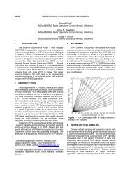
<strong>NEXRAD</strong>NowAir Traffic Controllers Using WSR-88D ProductsIt’s been a little more than a year since the FAA beganfull-fledged use of WSR-88D products as advisory overlayson the air traffic controller displays. So it might be agood opportunity to reintroduce ourselves and to discussour use of these important visual tools for aviation safety.In fact, we have anecdotal reports that controllers have asignificantly improved awareness of precipitation eventsthat could impact air traffic flows and safety. Departuresfrom Dallas-Ft. Worth were able to depart during a seriesof thunderstorms, because controllers could see where theweather was. Armed with this improved awareness, controllersare able to more efficiently manage their sectors.They can anticipate pilot requests to change their routingsto avoid weather and can report what they see more precisely.Can you assign a dollar figure to this? That’s the 6million dollar question, but we can say it’s a contributor inFAA efforts to create an infrastructure to promote efficiencyand safety.Air traffic controllers using WSR-88D products arecalled en route controllers. They are from 22 Air RouteTraffic Control <strong>Center</strong>s (ARTCCs) across the country,along with slightly smaller facilities in Alaska, Hawaii,Puerto Rico and Guam. They control aircraft during theirflights between airport terminal areas. (There are a fewtimes when en route controllers provide approach controlservices to aircraft at smaller airports or during contingencies.)But most of the time the approach to landing servicesare provided by terminal controllers in radarapproach control centers or in towers. The system usedby en route controllers to display WSR-88D products iscalled the Weather and <strong>Radar</strong> Processor, or WARP.WARP is just one tool in the National Airspace System orNAS. NAS automated systems include controller displays,state of the art communication systems, and supportsystems like WARP.Users of the WARP and WSR-88D products havedesignated focal points for FAA participation on WSR-88D Unit <strong>Radar</strong> Committees (URCs).WARP performs a wide array of functions, but theycan be listed as three basic ones. One function is to providemeteorologists and briefers with products similar tothose provided by the AWIPS used by Weather ForecastOffices and remoted to Central Weather Service Units(CWSUs). That function is used to analyze and compilebriefing graphics for ARTCCs. A second function ofWARP is to collect and distribute Rapid Update Cyclewind products to FAA computers that predict the futureflight paths of aircraft on Instrument Flight Rules (IFR)flight plans. The third function of WARP is to provide agraphic overlay that depicts areas of moderate or greaterprecipitation. This third function has created a time-sensitiveelement to use of the overlay products that we havenot had in the past.Controllers are not meteorologists, so they reportwhat they see on their display. Three colors are assignedto their display of precipitation: light cyan (greenish blue),royal blue and checkered cyan. An example of these canbe found in Figure 1. The light cyan is termed, “moderateweather.” Controllers phraseology for the other two colorsis “heavy weather.” We have learned that there canbe a small, but acceptable, time delay in the portrayal ofthe data, but this is overshadowed by the much more accuratedepiction now available to the controllers. Prior tothis improved display, controllers had to rely on their aircrafttracking radar – less than optimally tuned to viewprecipitation – and a generalized depiction of slash marks(///) for moderate weather and uppercase h’s (HHH) forheavy weather. Comparisons of the two reveal muchmore clarity of detail with the WSR-88D overlay.But this has been an evolutionary learning process.For example, the Weather Forecast Office (WFO) cancontrol the base altitude for lrml (known to us as Product65). The corresponding view on the controller scope is000 – 240 (surface to 24 thousand feet). The FAA discoveredthat the base altitude settings varied from WFO toWFO. When the base altitude is not set to the default setting,important weather conditions may be hidden fromthe controller’s view. So, until May of 2004, controllerswere instructed not to use this view, for obvious safetyreasons. (In February and May of 2004, the ROC releasedmaintenance messages to ensure this product is set to thedefault setting).Another learning process is being able to know whena single WSR-88D radar is degraded or out of service.The WARP system can alarm when the data flow betweenWSR-88Ds and FAA users is interrupted. However, westill do not have an automated way to inform air trafficcontrollers that a radar affecting their sector is not providingdata. For the time being, ARTCCs have to use a verbalnotification process. We’ve learned that free text messagescontribute greatly to our understanding of the reasonfor an outage. Estimates of system restoration are(Continued on Page 10)page 9
<strong>NEXRAD</strong>NowAir Traffic Controllers (Cont.)Figure 1: An FAA Air Traffic Controller’s Display System Replacement (DSR) with three-color precipitation displayed.(Continued from Page 9)extremely valuable as a planning tool.• To prevent air traffic controllers from missing possibleprecipitation events, verify and maintain the baselevel altitudes on products used for air traffic controllerdisplays. (Among these are Products 65, 67, 98.)• Invite FAA WSR-88D users to the Unit <strong>Radar</strong> Committeemeetings. URC points of contact may comefrom different offices at different ARTCCs. We areworking to provide the ROC with an up-to-date listingof FAA URC points of contact.• Help the FAA by use of clear free text messages containingreasons for outage and estimates for return toservice.• If possible, provide advance notice of planned systemoutages, even in advance of the use of free textmessages.• Visit the nearest ARTCC for a first-hand view ofWSR-88D use on controller displays.• Invite ARTCC WSR-88D users to visit your WFOand, if possible, your assigned WSR-88D facility.• Keep the CWSU in the loop.Steve Pelissier, FAASeattle, WA ARTCCRandy Wickers,Lockheed Martinpage 10
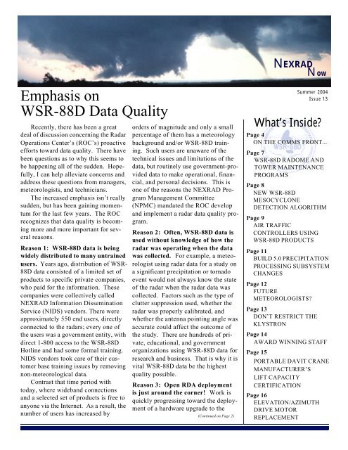
<strong>NEXRAD</strong>NowBuild 5.0 Precipitation Processing Subsystem ChangesAmong the most important changes introduced with<strong>Radar</strong> Products Generator (RPG) Build 5.0 software wasthe implementation of new Volume Coverage Patterns(VCPs), namely VCP 12 and VCP 121. VCP 121 hasthe same elevation angles as the legacy (original) VCP21. However, VCP 12 contains some elevation anglesnever used in WSR-88D legacy VCPs. Therefore, somechanges were made in the Precipitation Processing Subsystem(PPS): 1) the construction of the hybrid scanusing blockage files that enabled both new and prior elevationangles, 2) moving thresholds for initiation andend of accumulations from the Precipitation DetectionFunction (PDF) to a new version of the Hydromet Preprocessingalgorithm, 3) the reduction of clutter contaminationby the use of the <strong>Radar</strong> Echo Classifier (REC)instead of the legacy tilt test, and 4) the use of exclusionzones to ensure that ground returns, especially thoseclose to the radar, are not used in accumulations.The hybrid scan is a combination of reflectivity fromelevation angles and ranges that determine the reflectivitymost representative of precipitation reaching theground. Prior to Build 5.0 the PPS used static terrainbasedoccultation (or blockage) data and hybrid scansector definition files to build a hybrid scan reflectivity(HSR), which is the basis for precipitation computationsin the PPS. The static files could be used, because theelevation angles at or below 3.5° were approximately thesame for all legacy VCPs. Rather than create an additionalhybrid scan definition for each new VCP, the<strong>Radar</strong> Operation <strong>Center</strong> (ROC) and the NationalWeather Service (NWS) Office of Hydrologic Development(OHD) created a replacement for the original (legacy)Hydromet Preprocessing algorithm, calledEnhanced Preprocessing (EPRE), that allows precipitationestimates to be computed from a VCP with any elevationangles. The new PPS uses high resolution BeamBlockage Algorithm data files to aid in the constructionof the HSR.An additional change starting with Build 5.0 is theincorporation of initiation and end of precipitation accumulationsin the EPRE algorithm. This was previouslyperformed by the PDF, which included a parameter forthe detected area above a specified reflectivity level thatmust be exceeded before starting accumulation: theNominal Clutter Area (i.e., an area that is called clutter).This clutter area was a residual after clutter filtering(application of clutter suppression regions). Note thatclutter suppression affects base data, such as BaseReflectivity, and all products derived from them. TheNominal Clutter Area only affected precipitation accumulations.The equivalent parameter in the EPRE algorithmis RAINA. The threshold of reflectivity for theprecipitation area computation is the parameter, RAINZ,in decibels of reflectivity, dBZ. This was previously indecibels of rainfall rate, dBR, and identified as “PrecipRate Thrsh” in the PDF. The PDF remains in RPG softwareas the function that automatically causes the systemto change from Clear Air Mode to PrecipitationMode (VCP 21).The legacy PPS used the following tilt test to determinewhether the lowest angle had clutter contamination- if the reduction of coverage of significant echoesfrom the 0.5° elevation to the 1.5° elevation was greaterthan 75%, the lowest elevation angle was assumed to becontaminated and was discarded from the Hybrid Scan;the 1.5° angle was used instead. EPRE can eliminateclutter contamination from precipitation accumulationby using the REC. REC products, Clutter LikelihoodReflectivity (CLR) and Clutter Likelihood Doppler(CLD), are viewable as backgrounds on the RPGHuman Computer Interface (HCI) Clutter Regionsgraphical user interface. EPRE uses a percentage probabilityfrom the REC above which the radar returns areconsidered to be from clutter and are, therefore,excluded from accumulations. Because the new methoduses the lowest elevation angle whenever possible, theresulting accumulations may be higher than computedby the legacy PPS.Because Build 5.0 testing revealed there was stillsome residual ground clutter close to each radar site, itwas decided that the 500-foot rule would be applied inthe form of hard-coded exclusion zones. This excludesdata from being used in precipitation estimation for allelevations at or below 1.6° from a range of 0 to 5 nauticalmiles (nm), for all elevations at or below 1.0° from arange of 5 to 9 nm, and for all elevations at or below0.6° from a range of 9 to 25 nm from the radar. (SeeFigure 1 below for an illustration of these generic exclusionzones.) The result will sometimes be discernible“rings” in precipitation accumulations when there ispredominantly low stratiform precipitation, but will be(Continued on Page 12)page 11
Build 5.0 PPS Changes (Cont.)(Continued from Page 11)nearly imperceptible when there are convective storms.Additional exclusion zones can be created at each sitefor local contamination phenomena, such as wind farms,<strong>NEXRAD</strong>Nowthat would be hard to eliminate from the PPS using onlyclutter suppression regions and the REC.Dan BerkowitzROC Applications BranchFuture Meteorologists?A total of 16 children learned moreabout the <strong>NOAA</strong> Weather Partners duringTake Our Daughters and Sons to Work DayApril 22. The participants toured the StormPrediction <strong>Center</strong>, Norman Forecast Officeand <strong>Radar</strong> <strong>Operations</strong> <strong>Center</strong>, as well as thephased array radar at the National SevereStorms Laboratory. They viewed the newROC tour video, produced by ROC studentJames Murnan, and watched a presentationby Phillip Spencer from NSSL about differenttypes of weather and weather safety.The children especially enjoyed a presentationby Daphne Zaras from NSSL aboutstorm chasing that included a lot of videofootage. The NSSL/SPC Employees Associationtreated the participants to a cookoutfor lunch.Keli Tarp<strong>NOAA</strong> Weather Partnerspage 12Figure 1: Generic clutter exclusion zones.Participants from Left to Right: (Back Row) ROC Employees Scott Enders,Joe Chrisman, Cindy Chrisman, Mark Betsch, and student intern, JessicaSchultz. (Front Row) Sarah Enders, Ashley Chrisman, Rachel Chrisman,and Brianna Betsch.
Don’t Restrict the KlystronThe present WSR-88D Transmitter Technical Manual(NWS EHB 6-511 paragraph 7.8.6.5.4.2 step 54)limits the maximum Pulse Forming Network (PFN)voltage to 5000 volts. Recent research in the area oftransmitter tuning has revealed that this is an unnecessarilyrestrictive requirement. Here’s why:• The most restrictive requirement in the Modulatorand Klystron is the maximum Beam Voltage (epy)spec of the Klystron, Drawing Number 12<strong>13</strong>614,which states that a peak power output of 750 KWshall be obtained with an epy of 62KV max. ThePulse Transformer drawing, 156C742A01, specifiesa turns ratio step up of 28:1. The epy spec of62KV max then results in a primary voltage of2214 volts peak. The primary voltage divided by100 is available at 3A12TP2 (modulator). Incidentally,the Pulse Transformer permits an epy of65KV max.<strong>NEXRAD</strong>NowHow does this relate to PFN voltage? Transmissionline theory states that if a delay line (i.e., the PFN) ischarged and a switch (i.e., the RBDT stack) is closed, ifthe load impedance (looking into the pulse transformerprimary) is exactly equal to the source impedance (i.e.,the PFN characteristic impedance) exactly ½ of thecharged voltage will appear across the load (Primary ofpulse transformer) until the line is discharged with noover or undershoots. In practice, the perfectly matchedcondition is NOT realized so that the primary voltage is43% of the PFN voltage just prior to closing the ReverseBlocking Diode Thyristor (RBDT) switch and there areundershoots and/or overshoots. This can be seen in Figure1. Channel 1 is the PFN voltage at 3A12TP1. Itindicates a PFN voltage of 4930 volts. Channel 2 is thePulse Transformer primary voltage. This indicates avoltage of 21.20 X 100 = 2120 volts peak. This isequivalent to an epy of 2120 X 28 = 59.4 KV.(Continued on Page 14)Figure 1:Voltageovershootsandundershoots.page <strong>13</strong>
<strong>NEXRAD</strong>NowKlystron (Cont.)(Continued from Page <strong>13</strong>)• Empirical evidence indicates that the power vs. epyslope is 30+/- 5 KW/KV. In the case above, the PFNvoltage can be increased up to 62KV which resultsin an increase in power output of 2.6 KV X 30 KW/KV = 78 KW. This would result in a PFN of 5150volts. A Publications Change Request is being processedchanging the maximum PFN spec of 5000volts to an equivalent spec permitting a maximumvoltage at 3A12TP2 of 21.14 which is equivalent toan epy of 62KV peak.• Modulator considerations:Backswing diode stack - Prior to the introductionof ECP 0109, which added equalization resistorsacross the four diodes in the Backswing diodestack, handling the increase in PFN voltagewould be problematic. However, by this time, allof the stacks in the field should be modified. Noweach diode in the stack is rated at 2400 volts holdoffvoltage or a total of 4X2400 = 9600 volts minimum.An increase of PFN voltage up to 5150volts is obviously no problem for an equalizedstack. However, if an increase in PFN voltage isindicated, the Backswing stack should beAward Winning StaffThe WSR-88D program is staffed by dedicatedprofessionals around the world. Here at the ROC weare proud of our employees, many of whom have beenrecognized for their outstanding work and commitmentto excellence.The <strong>NOAA</strong> Administrator’s Award - A combinationhonorary and monetary award given annually inrecognition of employees or groups who have madesignificant contributions to <strong>NOAA</strong> programs. The followingwere recognized at a formal ceremony held inMay in the Silver Spring Auditorium:• For innovation and advances in engineeringdevelopment that enable faster implementation ofnew science into the nation’s weather radars -Sallie M. Ahlert, Terrell Ballard, Mark Betsch,Joe Chrisman, Scott Enders, Christopher Gilbert,Franklin Hewins, Chris Hunt, Larry Kitchell, andPaul Krenek.page 14checked to make sure it is equalized (P/N2500007-301) If this is not the case, the stackshould be replaced with an equalized stack.RBDT Stack - Each RBDT in the stack of 10series connected, equalized RBDT’s is rated toholdoff at least 1100 volts each or a total of 11000volts for the stack of 10. Again, the slight increasein PFN voltage is no problem.Transmitter Overvoltage Threshold level - Thelevel is set for a PFN voltage of 5600 volts.Increasing the PFN voltage to 5150 is no problem– the threshold should perform as designed.Many Klystrons are being returned from field siteswith a complaint of low power output. Based upon ananalysis of the repair data on returned tubes and theinformation in this article, almost all of these tubeswould still be in service if the new beam voltagerequirement had been applied. Therefore, technicalmanual changes have been submitted in an effort toavoid future voltage problems.William UrellROC Engineering Branch• For enhancing the weather warning service to thepublic by formulating and successfully managinga project to rescue valuable weather radar trainingdata - John Ferree, Edward Mahoney, andEdward Berkowitz.• For outstanding support in restoring NWS radarand upper air systems during the San Diego, CAfire (October-December 2003) - Ronald J. PattisonThe <strong>NOAA</strong> Technology Transfer Award• For the development of a national real-time radardata archival and Internet2 delivery system foruniversity, government and private sectors - TimCrum (as part of a group nomination submittedby <strong>NOAA</strong>’s Office of Oceanic and AtmosphericResearch.)(Continued on Page 15)
Awards (Cont.)(Continued from Page 14)The <strong>NOAA</strong> Team Member of the Month Awardfor April 2004 was presented to Rich Ice, RC InformationSystems (RSIS). This award pays tribute to a non-<strong>NOAA</strong> employee and gives credit to the outstandingpeople who make <strong>NOAA</strong> programs a success but arenot actually Federal employees.The Oklahoma Federal Executive Board FederalEmployee of the Year Award was established inan effort to recognize outstanding federal employeesfor their efforts, leadership and/or initiative. This programencourages innovation and excellence in government,reinforces pride in federal service, and helps callpublic attention to the broad range of services providedby federal employees. The 2004 Oklahoma FederalExecutive Board Federal Employee of the Year Programrecognized nominees Terrell Ballard, 1st Lt. RonFehlen, Erin Foster, MSgt Greg Matthews, Maj.Michael Miller, Janalee Pacheco, Rex Reed and DaveZittel. Nominees and winners received a plaque at abanquet held at the Tinker AFB Officer’s Club on May3, 2004. At which time, Rex Reed was awarded SupervisoryFederal Executive Board Employee of the Year.The ROC Employee of the Quarter (EOQ) andTeam Member of the Quarter (TMOQ) Awardswere established for the ROC Awards Program to recognizepeople who;• Demonstrate exceptional performance• Exceed normal customer service• Perform a worthy non-duty related act• Accomplish a unique short-term project or specialassignment• Accomplish an office productivity and efficiencyenhancement of procedures<strong>NEXRAD</strong>Now• Produce an office morale enhancement throughteamwork.This quarterly awards program began in October2001 with representatives from each organizationwithin the ROC. The ROC award team representativesare a group of proactive volunteers dedicated to providinghard working individuals with the appreciationthey deserve. This team consists of people who selflesslystepped up to create and implement an internalaward program as desired by the ROC employees. Theteam’s birthplace was the Y2K/US vs. Them - Contractor/Tri-agencyRelations presentation to the seniorROC staff on July 7, 1999.Winners of the EOQ and TMOQ are presentedwith a framed certificate signed by the ROC Directorand the winner’s name is engraved on a plaque in thelarge conference room in the ROC South building andon a plaque in the lobby of the ROC North facility.Winners are also considered for <strong>NOAA</strong> Employee andTeam Member of the Quarter and other awards.The winner of the Employee of the Quarter for thesecond quarter fiscal year 2004 is 1st Lt. Ron Fehlen, amember of the U.S. Air Force, and the winner for theTeam Member of the Quarter is Matt King, anemployee of Management and Engineering TechnologiesInternational (METI). Both members are assignedto the ROC Engineering Branch.Nancy OlsonROC Administrative OfficerTSgt David RiffleUSAF/ROC Program BranchPortable Davit Crane Manufacturer’s Lift Capacity CertificationBoth Occupational Safety and Health Administration(OSHA) and EHB-15, WSR-88D OccupationalSafety and Health Manual, require that each facilitymaintain a certification of the capacity of all liftingdevices. The manufacturer of the WSR-88D PortableDavit Crane has provided a letter that certifies that allcranes purchased by the National Weather Servicehave been appropriately load tested. This letter isprovided for your records. Click on this link to displaythe letter. Then please print the certification letterand retain it on file.Marty Williams, RMT Team LeadROC Program Branchpage 15
Elevation/Azimuth Drive Motor ReplacementMike Hazel, ET at KPAH (Paducah, KY) submittedthe following helpful “tip” for replacing the elevation/azimuth drive motor:Materials required:4 - 5/16 x 12” Allthread4 – 5/16 coupling nutsAt EHB 6-510, RDA Maintenance Manual, paragraph6-5.52.1.3 step 7 - elevation (EHB 6-510, paragraph6-5.52.7.3 step 3 - azimuth), remove 4 of the 6<strong>NEXRAD</strong>Nowhex-head bolts from the adapter housing holding themotor in place. Insert the allthread into the emptyholes and tighten the coupling nuts to hold the motor inplace (Figures 2 and 3). Remove the 2 remaining hexheadbolts, loosen the flexible coupling, and then lowerthe motor by loosening the coupling nuts until themotor is free.Install the motor by sliding the motor onto theallthread and then putting on the coupling nuts. Thiswill hold the motor in place. The motor can now belifted and the coupling nuts turned until the motor isproperly seated. This will eliminate any strain on theflexible coupling (not to mention your arms and back)and the motor will slide correctly into place with littleeffort.Technical manual changes have been submitted forthis procedure, which will be removed from EHB 6-510 and included in the new combined pedestal manual.David HazelKPAH, Paducah, KYTim StanleyKJKL, Jackson, KYFigure 1: Required Materials.Figure 2: Close-up of installed allthreads.page 16Figure 3: Allthreads installed.