VISTA V3 Install Instructions - Hes
VISTA V3 Install Instructions - Hes
VISTA V3 Install Instructions - Hes

You also want an ePaper? Increase the reach of your titles
YUMPU automatically turns print PDFs into web optimized ePapers that Google loves.
<strong>Install</strong>ation <strong>Instructions</strong><br />
®<br />
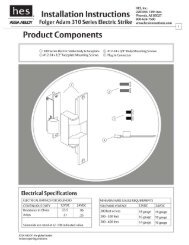
Vista <strong>V3</strong> Electric Strike<br />
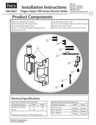
Product Components<br />
HES, Inc.<br />
Phoenix, AZ<br />
800-626-7590<br />
www.hesinnovations.com<br />
1<br />
15/16”<br />
1-13/16”<br />
13/16”<br />
1 Strike Body<br />
2 Keeper Shims 3 4-40 x 1/8” Shim Screws<br />
4 4-40 x 3/16” Shim Screws<br />
5 Option Kit<br />
(sold separately)<br />
Strike <strong>Install</strong>ation<br />
1. If this is a new installation, consult pages 2-3 for the<br />
proper template for your option.<br />
2. If you are replacing another manufacturer’s electric strike,<br />
first determine the manufacturer and model number to be<br />
replaced. Using the chart on page 4, choose the appropriate<br />
Option Kit and spacer to be used with the new install and<br />
proceed to step 3.<br />
Faceplate and Housing Assembly<br />
3. Attach Electric Strike body to Housing as illustrated<br />
below using the 6-32 x 5/16” socket head screws and hex key<br />
packaged with the Option Kit.<br />
6-32 x 5/16”<br />
Socket Head<br />
Screws<br />
4. If using Options 1-4, attach Faceplate to Housing as illustrated<br />
below using the 6-32 x 7/16” flat-head screws provided with the<br />
Option Kit.<br />
Note: A second set of mounting holes is provided in the Housing<br />
for additional Forward Horizontal Adjustment.<br />
6-32 x 7/16” Faceplate<br />
screws<br />
Strike Body<br />
Faceplate<br />
Housing<br />
Complete <strong>Install</strong>ation<br />
5. <strong>Install</strong> Electric Strike assembly into frame to test latchbolt<br />
interaction.<br />
6. If additional horizontal adjustment is needed, 1 or 2 keeper<br />
shims can be added as illustrated below. If adding a single shim<br />
use the 4-40 x 1/8” screws, or if adding both shims, the longer<br />
4-40 x 3/16” screws should be used.<br />
7. Remove Electric Strike from frame and connect power.<br />
8. Re-install the electric strike into jamb cutout using the<br />
12-24 flat-head screws provided in the Option Kit to complete<br />
installation.
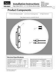
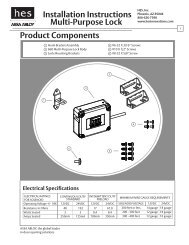
Cutout Templates<br />
2<br />
OPTION 1<br />
4-7/8” x 1-1/4” Square Corner Faceplate<br />
ANSI Metal Jamb <strong>Install</strong>ations<br />
NEW INSTALLATION<br />
1 -1/4"<br />
[31.8]<br />
OPTION 1A<br />
4-7/8” x 1-1/4” Radius Corner Faceplate<br />
Metal Frame <strong>Install</strong>ations With Mounting Tabs<br />
NEW INSTALLATION<br />
1 -1/4"<br />
[31.8]<br />
3 -3/8"<br />
[85.7]<br />
4 -7/8"<br />
[124]<br />
3 -3/8"<br />
[85.7]<br />
4 -7/8"<br />
[124]<br />
21/32"*<br />
[16.7]<br />
3/32"<br />
[2.3]<br />
Inches<br />
[mm]<br />
21/32"*<br />
[16.7]<br />
3/32"<br />
[2.3]<br />
Inches<br />
[mm]<br />
RETROFIT: COMPATIBLE CUTOUTS<br />
RCI 4114 ROFU 1702<br />
RCI 7114 ROFU 1802<br />
*Dimension shown without spacer<br />
Trine 012<br />
Trine 2007<br />
Trine 2012<br />
RETROFIT: COMPATIBLE CUTOUTS<br />
RCI 4104<br />
RCI 7104<br />
OPTION 2 OPTION 3<br />
7-15/16” x 1-7/16” Radius Corner Faceplate<br />
Metal Frame <strong>Install</strong>ations With Mounting Tabs<br />
*Dimension shown without spacer<br />
6 -7/8” x 1-1/4” Radius Corner Faceplate<br />
Metal Frame <strong>Install</strong>ations With Mounting Tabs<br />
NEW INSTALLATION<br />
1 -7/16"<br />
[36.5]<br />
NEW INSTALLATION<br />
1 -1/4"<br />
[31.8]<br />
3 -3/8"<br />
[85.7]<br />
7 -15/16"<br />
[201.6]<br />
3 -3/8"<br />
[85.7]<br />
6 -7/8"<br />
[174.3]<br />
21/32"*<br />
[16.7]<br />
21/32"*<br />
[16.7]<br />
3/32"<br />
[2.3]<br />
Inches<br />
[mm]<br />
3/32"<br />
[2.3]<br />
Inches<br />
[mm]<br />
RETROFIT: COMPATIBLE CUTOUTS<br />
RETROFIT: COMPATIBLE CUTOUTS<br />
RCI 7108<br />
RCI 4108<br />
ROFU 1704<br />
ROFU 1804<br />
Trine 2002WR<br />
RCI 4107 ROFU 1703 Trine 2678<br />
RCI 7107 ROFU 1803<br />
*Dimension shown without spacer<br />
*Dimension shown without spacer
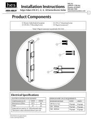
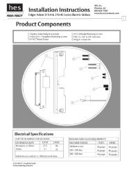
Cutout Templates<br />
3<br />
OPTION 4<br />
9” x 1-3/8” Radius Corner & Flat Faceplate<br />
Wood Frame <strong>Install</strong>ations<br />
NEW INSTALLATION<br />
1 -3/8"<br />
[34.9]<br />
9"<br />
[230]<br />
1 -1/4"<br />
[31.8]<br />
OPTION 5<br />
3-1/2” x 1-3/8” Square Corner & Flat Faceplate<br />
Wood Frame <strong>Install</strong>ations<br />
NEW INSTALLATION<br />
1-1/2 "<br />
[38.1]<br />
1 -3/8"<br />
[34.9]<br />
1 -7/8"<br />
[46]<br />
3 -1/2"<br />
[88.9]<br />
3 -3/8"<br />
[85.7]<br />
21/32"*<br />
[16.7]<br />
3/32"<br />
[2.3]<br />
Inches<br />
[mm]<br />
3/8"<br />
[9.5]<br />
3/32"<br />
[2.4]<br />
Inches<br />
[mm]<br />
RETROFIT: COMPATIBLE CUTOUTS<br />
ANSI 9” X 1-3/8” CUTOUTS<br />
RETROFIT: COMPATIBLE CUTOUTS<br />
Trine 005<br />
*Dimension shown without spacer<br />
NEW INSTALLATION<br />
OPTION 6<br />
7-15/16” x 1-7/16” Radius Corner Faceplate<br />
Metal frame with mounting tabs or Wood <strong>Install</strong>ations<br />
1 -7/16"<br />
[36.5]<br />
NEW INSTALLATION<br />
OPTION 7 & 7E<br />
2-3/4” x 1-1/8” Square Corner Faceplate<br />
ANSI A156.115 2-3/4”Metal Jamb <strong>Install</strong>ation*<br />
1 -1/8"<br />
[28.6]<br />
2-7/8"<br />
[73]<br />
7 -15/16"<br />
[201.6]<br />
A<br />
B<br />
2 -3/4"<br />
[69.9]<br />
13/16"<br />
[20.6]<br />
C<br />
3/16"<br />
[4.8]<br />
Inches<br />
[mm]<br />
1/8"<br />
[3.2]<br />
Inches<br />
[mm]<br />
RETROFIT: COMPATIBLE CUTOUTS<br />
ROFU 1509<br />
RETROFIT: COMPATIBLE CUTOUTS<br />
ANSI A156.115 2-3/4 CUTOUTS*<br />
A B C<br />
Option 7* 1-1/2” [38.1] 1-7/8”[46] 5/8” [15.8]<br />
Option 7E 2” [ 50.8] 2” [50.8] 21/32”[16.7]
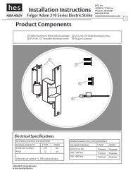
Compatibility Chart & Specifications<br />
4<br />
OPTION KIT SELECTION<br />
1. Using the chart below determine which Vista 3 Option Kit is required for your application.<br />
Red/Green<br />
Note: Depending on the product being retrofitted, you are choosing both a faceplate, and spacer option.<br />
Black<br />
For example, when replacing a Trine 2002WR series strike, an Option Kit 2 should<br />
be used, as well as spacer #2. No spacer is needed if “None” is listed under spacer.<br />
Trine Model<br />
2002WR<br />
Vista Option Kit<br />
2<br />
Spacer<br />
Spacer #2<br />
Model Vista Option Kit Spacer Used<br />
RCI<br />
4104 1A Yes: Spacer #1<br />
4114 1 Yes: Spacer #1<br />
4107 3 Yes: Spacer #1<br />
4108 2 Yes: Spacer #1<br />
7104 1A Yes: Spacer #1<br />
7114 1 Yes: Spacer #1<br />
7107 3 Yes: Spacer #1<br />
7108 2 Yes: Spacer #1<br />
Housing With No Spacer<br />
Housing With Spacer #1<br />
21/32"<br />
[16.7]<br />
7/8"<br />
[22.2]<br />
ROFU<br />
TRINE<br />
Model Vista Option Kit Spacer Used<br />
1509 6 None<br />
1702 1 None<br />
1703 3 None<br />
1704 2 None<br />
1802 1 None<br />
1803 3 None<br />
1804 2 None<br />
005 5 None<br />
012 1 Yes: Spacer #2<br />
2002WR 2 Yes: Spacer #2<br />
2007 1 None<br />
2012 1 Yes: Spacer #2<br />
2678 3 Yes: Spacer #2<br />
Housing With Spacer #2<br />
13/16"<br />
[20.6]<br />
ELECTRICAL SPECIFICATIONS<br />
CAUTION! This strike is provided as either a 12 or 24 volt unit. Before connecting any device at the installation site,<br />
verify input voltage using a multimeter. Many power supplies and low voltage transformers operate at higher levels<br />
than listed. Any input voltage exceeding 10% of the solenoid rating may cause severe damage to the unit and will void<br />
the warranty.<br />
inches<br />
[mm]<br />
ELECTRICAL RATINGS FOR SOLENOID<br />
CONTINUOUS DUTY<br />
INTERMITTENT DUTY*<br />
MINIMUM WIRE GAUGE REQUIREMENTS<br />
SOLENOID VOLTAGE<br />
12VDC<br />
24VDC<br />
12-16VAC<br />
24VAC<br />
12VDC<br />
24VDC<br />
Resistance in Ohms<br />
60<br />
240 60 240<br />
200 feet or less<br />
18 gauge<br />
18 gauge<br />
Amps<br />
.20<br />
Solenoids are rated at +/- 10% indicated value.<br />
*10% max duty cycle (2 min. max on time).<br />
.10 .20 .10<br />
200 - 300 feet<br />
300 - 400 feet<br />
16 gauge<br />
14 gauge<br />
18 gauge<br />
16 gauge<br />
3603006.001 rev E<br />
© 2012 HES, Inc.