FOLGER ADAM 310-4-2 Install Instructions.pdf - Hes
FOLGER ADAM 310-4-2 Install Instructions.pdf - Hes
FOLGER ADAM 310-4-2 Install Instructions.pdf - Hes

Create successful ePaper yourself
Turn your PDF publications into a flip-book with our unique Google optimized e-Paper software.
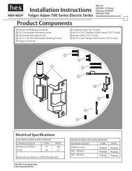
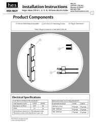
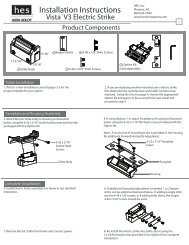
<strong>Install</strong>ation <strong>Instructions</strong><br />
Folger Adam <strong>310</strong>-4-1, -2, -3, -30 Series Electric Strike<br />
Product Components<br />
HES, Inc.<br />
22630 N. 17th Ave.<br />
Phoenix, AZ 85027<br />
800-626-7590<br />
www.hesinnovations.com<br />
1<br />
1<br />
2<br />
Electric Strike Body & Faceplate 3<br />
1/4-20 x 1” Mounting Screws 4<br />
#14 x 2” Mounting Screws<br />
Plug In Connectors*<br />
*Only 1 Plug In Connector is used with <strong>310</strong>-4-30<br />
1<br />
2<br />
3<br />
4<br />
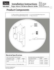
Electrical Specifications<br />
ELECTRICAL RATINGS FOR SOLENOID*<br />
MINIMUM WIRE GAUGE REQUIREMENTS<br />
CONTINUOUS DUTY 12VDC 24VDC<br />
SOLENOID VOLTAGE 12VDC<br />
Resistance in Ohms<br />
23.5 96<br />
200 feet or less<br />
18 gauge<br />
Amps<br />
.51 .25<br />
200 - 300 feet<br />
16 gauge<br />
Solenoids are rated at +/- 10% indicated value.<br />
300 - 400 feet<br />
14 gauge<br />
*Resistance value indicated above is per coil.<br />
24VDC<br />
18 gauge<br />
18 gauge<br />
16 gauge
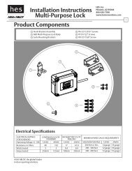
<strong>Install</strong>ation Directions<br />
2<br />
CAUTION! Before connecting any device at the installation site, verify input voltage using a multimeter.<br />
Many power supplies and low voltage transformers operate at higher levels than listed. Any input voltage exceeding<br />
10% of the solenoid rating may cause severe damage to the unit and will void the warranty.<br />
Prepare Strike<br />
1. If using the LCBMA (Latchbolt Monitor & Locking Cam<br />
Monitor), see Diagram 1 for wiring instructions.<br />
2. The strike body ships as either a 12 or 24 volt<br />
unit and is not field selectable. Verify the available<br />
voltage is +/- 10% of the rated voltage of the strike body.<br />
Finish <strong>Install</strong>ing<br />
4. Connect the Plug In Connector to the electric strike, and<br />
connect wires from the Plug In Connector leads to the<br />
power source.<br />
5. <strong>Install</strong> the electric strike unit in jamb cutout, using the<br />
1/4-20 x 1” mounting screws for metal applications, or<br />
the #14 x 2” screws for wood applications.<br />
Prepare Frame<br />
3. Prepare frame using the template for your strike<br />
located on pages 3-4.<br />
Diagram 1: Monitoring Switches<br />
Latchbolt Monitor (LBM)<br />
White Common<br />
Orange Normally Open<br />
Green Normally Closed<br />
Locking Cam Monitor (LCM)<br />
Brown<br />
Blue<br />
Common<br />
Normally Open<br />
Yellow Normally Closed<br />
White<br />
Orange<br />
Green<br />
Brown<br />
Blue<br />
Yellow
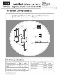
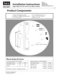
Cutout Templates<br />
<strong>310</strong>-4-1 Template & Dimensions<br />
Inches [mm]<br />
3<br />
3-15/16”<br />
[100.08]<br />
C L<br />
12-5/8”<br />
"B<br />
[320.68]<br />
12-1/4”<br />
"C "<br />
[311.15]<br />
4-3/8”<br />
"A"<br />
[111.13]<br />
C L<br />
3-15/16”<br />
[100.08]<br />
Center line of electric<br />
strike & latchbolt of<br />
lock must align<br />
3/16”<br />
[4.75]<br />
11/16”<br />
[17.45]<br />
1-5/16”<br />
[33.32]<br />
Drill & tap 1/4” x 20<br />
thru (2 places)<br />
2-3/4<br />
(69.85)<br />
1-5/8<br />
(41.28)<br />
4-1/2<br />
(11.43)<br />
13-3/8”<br />
[339.73]<br />
12-5/8”<br />
[320.68]<br />
4-3/8”<br />
[111.13]<br />
5/8<br />
(15.88)<br />
3/4<br />
(19.05)<br />
1-5/8<br />
(41.28)<br />
4-1/2<br />
(11.43)<br />
1-11/16<br />
(42.86)<br />
1-1/2<br />
(38.10)<br />
3/4<br />
(19.05)<br />
Reinforce jamb for tapped<br />
holes (10 gauge minimum,<br />
2 places)<br />
<strong>310</strong>-4-2 Template & Dimensions<br />
3-15/16”<br />
[100.08]<br />
C L<br />
13-1/4”<br />
"B<br />
[336.55]<br />
12-7/8”<br />
"C "<br />
[327.03]<br />
5”<br />
"A"<br />
[127]<br />
C L<br />
3-15/16”<br />
[100.08]<br />
Center line of electric<br />
strike & latchbolt of<br />
lock must align<br />
3/16”<br />
[4.75]<br />
11/16”<br />
[17.45]<br />
1-5/16”<br />
[33.32]<br />
Drill & tap 1/4” x 20<br />
thru (2 places)<br />
2-3/4<br />
(69.85)<br />
1-5/8<br />
(41.28)<br />
4-1/2<br />
(11.43)<br />
14”<br />
[355.60]<br />
13-1/4”<br />
[336.55]<br />
5”<br />
[127]<br />
5/8<br />
(15.88)<br />
3/4<br />
(19.05)<br />
1-5/8<br />
(41.28)<br />
4-1/2<br />
(11.43)<br />
1-11/16<br />
(42.86)<br />
1-1/2<br />
(38.10)<br />
3/4<br />
(19.05)<br />
Reinforce jamb for tapped<br />
holes (10 gauge minimum,<br />
2 places)
Cutout Templates<br />
<strong>310</strong>-4-3 Template & Dimensions<br />
Inches [mm]<br />
4<br />
3-15/16”<br />
[100.08]<br />
C L<br />
13-7/8”<br />
"B<br />
[352.43]<br />
13.5”<br />
"C "<br />
[342.90]<br />
5-5/8”<br />
"A"<br />
[142.88]<br />
C L<br />
3-15/16”<br />
[100.08]<br />
Center line of electric<br />
strike & latchbolt of<br />
lock must align<br />
3/16”<br />
[4.75]<br />
11/16”<br />
[17.45]<br />
1-5/16”<br />
[33.32]<br />
Drill & tap 1/4” x 20<br />
thru (2 places)<br />
2-3/4<br />
(69.85)<br />
1-5/8<br />
(41.28)<br />
4-1/2<br />
(11.43)<br />
14-5/8”<br />
[371.48]<br />
13-7/8”<br />
[352.43]<br />
5-5/8”<br />
[142.88]<br />
5/8<br />
(15.88)<br />
3/4<br />
(19.05)<br />
1-5/8<br />
(41.28)<br />
4-1/2<br />
(11.43)<br />
1-11/16<br />
(42.86)<br />
1-1/2<br />
(38.10)<br />
3/4<br />
(19.05)<br />
Reinforce jamb for tapped<br />
holes (10 gauge minimum,<br />
2 places)<br />
<strong>310</strong>-4-30 Template & Dimensions<br />
3-15/16”<br />
[100.08]<br />
C L<br />
11-1/4”<br />
"B<br />
[285.75]<br />
10-7/8”<br />
"C "<br />
[304.80]<br />
3”<br />
"A"<br />
[76.2]<br />
C L<br />
3-15/16”<br />
[100.08]<br />
Center line of electric<br />
strike & latchbolt of<br />
lock must align<br />
3/16”<br />
[4.75]<br />
11/16”<br />
[17.45]<br />
1-5/16”<br />
[33.32]<br />
Drill & tap 1/4” x 20<br />
thru (2 places)<br />
2-3/4<br />
(69.85)<br />
1-5/8<br />
(41.28)<br />
4-1/2<br />
(11.43)<br />
12”<br />
[304.80]<br />
11-1/4”<br />
[285.75]<br />
3”<br />
[76.20]<br />
5/8<br />
(15.88)<br />
3/4<br />
(19.05)<br />
1-5/8<br />
(41.28)<br />
4-1/2<br />
(11.43)<br />
1-11/16<br />
(42.86)<br />
1-1/2<br />
(38.10)<br />
3/4<br />
(19.05)<br />
Reinforce jamb for tapped<br />
holes (10 gauge minimum,<br />
2 places)<br />
3810006.003 rev A © 2010 HES, Inc.