

Pipe Flow Calculations - Clarkson University
Pipe Flow Calculations - Clarkson University
Pipe Flow Calculations - Clarkson University

Create successful ePaper yourself
Turn your PDF publications into a flip-book with our unique Google optimized e-Paper software.
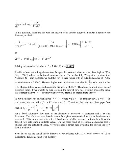
1 ⎡ 1.26 ⎤<br />
= − 4.0 log10<br />
⎢ ⎥<br />
f<br />
⎢⎣Re<br />
f ⎥⎦<br />
In this equation, substitute for both the friction factor and the Reynolds number in terms of the<br />
diameter, to obtain<br />
⎡ ⎤ −5<br />
⎡ × ⎤<br />
4.0 log<br />
5/2 10<br />
⎢<br />
⎥ 4.0 log10<br />
3/2<br />
1 1.26 2.25 10<br />
=− =−<br />
3 5/2<br />
47.5D<br />
⎢<br />
( 1.18 10 / D) ( 47.5 D )<br />
D<br />
⎥<br />
⎢⎣<br />
× × ⎥⎦<br />
⎣ ⎦<br />
or<br />
D<br />
=− 190 log ⎡<br />
⎣2.25×<br />
10<br />
D<br />
−5/2 −5 −3/2<br />
10<br />
⎤<br />
⎦<br />
Solving this equation, we obtain<br />
−2<br />
7.91 10 0.949"<br />
D = × ft =<br />
A table of standard tubing dimensions for specified nominal diameters and Birmingham Wire<br />
Gage (BWG) values can be found in many places. The textbook by Welty et al. provides it as<br />
Appendix N. From the table, we find that for 14-gage tubing with an outside diameter of 1" , the<br />
1<br />
inside diameter is 0.834”. The next higher outside diameter available is 1 − inch , and for this<br />
4<br />
OD, 14-gage tubing comes with an inside diameter of 1.084”. Therefore, we must select one of<br />
these two tubes. If we want to be sure to obtain the desired flow rate, we must choose the value<br />
that is larger than 0.949” . You may wonder why. Here is an approximate answer.<br />
In turbulent flow, the friction factor f ∝ V −a , where 0≤<br />
a < 1. In laminar flow, f ∝ V −1 . In<br />
2 b<br />
both cases, we can write fV ∝ V where b > 0 . Therefore, the head loss from pipe flow<br />
1 2⎛2L<br />
⎞ 1 2 1 b<br />
friction hf<br />
= fV ⎜ ⎟∝ fV ∝ V<br />
D ⎝ g ⎠ D D<br />
For a fixed volumetric flow rate, as the diameter is increased, V b decreases and 1/ D also<br />
decreases. Therefore, the head loss decreases for a given volumetric flow rate as the diameter is<br />
increased. This means that with a fixed head loss available, we can comfortably achieve the<br />
desired flow rate using a suitable valve. On the other hand, if we choose a diameter that is<br />
smaller than the calculated value, we would need a larger head available for driving the flow<br />
than is available.<br />
Now, let us use the actual inside diameter of the selected tube,<br />
evaluate the Reynolds number of the flow.<br />
D<br />
−2<br />
= 1.084" = 9.03× 10 ft to<br />
10


