Installation & Servicing Instructions - Grant UK
Installation & Servicing Instructions - Grant UK
Installation & Servicing Instructions - Grant UK

Create successful ePaper yourself
Turn your PDF publications into a flip-book with our unique Google optimized e-Paper software.
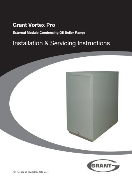
<strong>Grant</strong> Vortex Pro<br />
External Module Condensing Oil Boiler Range<br />
<strong>Installation</strong> & <strong>Servicing</strong> <strong>Instructions</strong><br />
Part No. Doc 52 Rev.06 May 2012 D314
Commissioning Report<br />
For use with Kerosene* only.<br />
After installing the boiler leave these<br />
instructions with the User.<br />
This appliance is deemed a controlled<br />
service and specific regional statutory<br />
requirements may be applicable.<br />
*Operation on Bio-fuel<br />
Date:_______________________________<br />
Commissioning Engineer:_______________________________________________<br />
Tel. No:____________________________<br />
Boiler model:_______________________ Boiler output:________________ kW<br />
All <strong>Grant</strong> Vortex Pro condensing boilers,<br />
manufactured since May 2011, are suitable<br />
for operation on both standard kerosene<br />
(Class C2 to BS2869) and also bio-kerosene<br />
– up to a 30% blend (B30K).<br />
All burner settings and nozzle sizes (as<br />
detailed in Section 2.3 of this manual)<br />
are correct for both standard kerosene<br />
and bio-kerosene (B30K).<br />
In order to operate this boiler on biokerosene<br />
it will be necessary to take<br />
the following actions:<br />
Fuel type: Kerosene / Bio-Kerosene<br />
Nozzle size:_________________________<br />
Air setting:__________________________<br />
Net flue gas temp:___________________<br />
System flushed: yes / no<br />
Antifreeze added: yes / no<br />
Pump pressure:__________________<br />
Flue gas % CO 2<br />
:_________________<br />
Smoke No:______________________<br />
Corrosion inhibitor added: yes / no<br />
a) Use a bio-kerosene (B30K)<br />
compatible flexible oil line in place of<br />
the oil line supplied with this boiler.<br />
b) Have your oil storage tank and oil<br />
supply line (including all pipework,<br />
sight gauges, filters, isolating valves,<br />
fire valves, de-aeration devices, etc.)<br />
checked for their compatibility with<br />
bio-kerosene (B30K).<br />
Where necessary some, or all, of these<br />
items may have to be replaced with a<br />
bio-kerosene compatible alternative.<br />
c) Check the suitability of the flue system<br />
with <strong>Grant</strong> <strong>UK</strong>.<br />
d) Use only bio-kerosene (B30K) that<br />
conforms to OPS24.<br />
For Sealed systems only:<br />
Expansion vessel size:_ _____________________ litres<br />
Expansion vessel charge pressure:_ __________ bar<br />
Sealed system fill pressure (cold):____________ bar<br />
Service Log<br />
It is recommended that the boiler should be regularly serviced, at least once a year,<br />
and the details entered in the Boiler Handbook by the service engineer.<br />
IMPORTANT<br />
Under no circumstances should the<br />
boiler be used with bio-kerosene without<br />
the above actions being taken first.<br />
Commissioning<br />
Report<br />
<strong>Grant</strong> Engineering (<strong>UK</strong>) Limited<br />
Hopton House, Hopton Industrial Estate, Devizes, Wiltshire SN10 2EU<br />
Tel: 01380 736920 Fax: 01380 736991<br />
Email: sales@grantuk.com www.grantuk.com<br />
2<br />
This manual is accurate at the date of printing but will be superseded and should be disregarded if specifications and/or<br />
appearances are changed in the interests of continued product improvement.<br />
All goods sold are subject to our official Conditions of Sale, a copy of which may be obtained on application.<br />
© <strong>Grant</strong> Engineering (<strong>UK</strong>) Limited 2012. No part of this manual may be reproduced by any means without prior written consent.
Contents<br />
1 Introduction 4<br />
1.1 How a condensing boiler works 4<br />
1.2 Boiler description 4<br />
1.3 Boiler components 5<br />
2 Technical Data 6<br />
2.1 Boiler technical data 6<br />
2.2 Sealed system data 6<br />
2.3 Vortex boiler using Class C2 kerosene 7<br />
2.4 Water connections 7<br />
2.5 Flue gas analysis 7<br />
2.6 Boiler dimensions 8<br />
3 Oil Storage & Supply System 10<br />
3.1 Fuel supply 10<br />
3.2 Burner oil connection 11<br />
4 Boiler <strong>Installation</strong> Information 13<br />
4.1 Introduction 13<br />
4.2 Boiler location 13<br />
4.3 Preparation for installation 13<br />
4.4 Installing the boiler 14<br />
4.5 Regulations compliance 14<br />
4.6 Completion 14<br />
4.7 Before you commission 14<br />
4.8 Heating system design considerations 15<br />
4.9 Underfloor heating systems 15<br />
4.10 Pipework materials 15<br />
4.11 Sealed systems 15<br />
4.12 Underfloor pipework 15<br />
5 Pipe Connections 16<br />
5.1 Water connections 16<br />
6 Condensate Disposal 17<br />
6.1 General requirements 17<br />
6.2 Connections 17<br />
6.3 Pipework 17<br />
6.4 External pipework 17<br />
6.5 Condensate soakaway 17<br />
6.6 Condensate trap 18<br />
6.7 Condensate disposal pipework 18<br />
6.8 Inspection and cleaning of trap 18<br />
7 Sealed Systems 19<br />
7.1 Sealed system installation 19<br />
7.2 15/21 Sealed system kit 19<br />
7.3 15/26 Sealed system kit 20<br />
7.4 26/36, 36/46 Sealed system kit 21<br />
7.5 Fit the expansion vessel 22<br />
7.6 Fill the sealed system 22<br />
7.7 Vent the pump 22<br />
7.8 Pressure relief safety valve 22<br />
8 Electrical 23<br />
8.1 Connecting the power supply 23<br />
8.2 Frost protection 23<br />
8.3 Control system wiring diagrams 24<br />
8.4 Boiler control panel wiring diagrams 26<br />
9 Flue System and Air Supply 27<br />
9.1 Low level discharge 27<br />
9.2 <strong>Grant</strong> green system 27<br />
9.3 <strong>Grant</strong> hybrid system 29<br />
9.4 <strong>Grant</strong> horizontal system 30<br />
9.5 Conventional flue systems 30<br />
9.6 Air supply 30<br />
10 Commissioning 31<br />
10.1 Before switching on 31<br />
10.2 Switching on 31<br />
10.3 Running the boiler 32<br />
10.4 Balancing the system 32<br />
10.5 Completion 32<br />
10.6 Air adjuster disc - 15/21 only 32<br />
11 Boiler <strong>Servicing</strong> 33<br />
11.1 Check before servicing 33<br />
11.2 Dismantling prior to servicing 33<br />
11.3 Cleaning the boiler 33<br />
11.4 Cleaning the burner 34<br />
12 Fault Finding 37<br />
12.1 Boiler fault finding 37<br />
12.2 Burner fault finding 38<br />
13 Spare Parts 39<br />
13.1 Boiler spares 39<br />
13.2 Burner heads 39<br />
13.3 Riello RDB1, 2, 2.2 burner spares 40<br />
13.4 Riello RDB3.2 burner spares 42<br />
14 Health & Safety Information 44<br />
14.1 Insulation materials 44<br />
14.2 Sealant materials 44<br />
14.3 Kerosene and gas oil fuels (mineral oils) 44<br />
15 EC Declaration of Conformity 45<br />
16 Warranty 46<br />
17 Notes 48<br />
Contents<br />
3
1 Introduction<br />
Introduction<br />
This manual is intended to guide<br />
engineers in the installation and<br />
maintenance of <strong>Grant</strong> VORTEX Pro<br />
External modules. A User guide for the<br />
operation of this boiler is attached to<br />
the reverse of this manual.<br />
The following special text formats are<br />
used in this manual for the purposes<br />
listed below:<br />
!<br />
Warning of possible human injury as<br />
a consequence of not following the<br />
instructions in the warning.<br />
!<br />
Caution concerning likely damage<br />
to equipment or tools as a<br />
consequence of not following the<br />
instructions in the caution.<br />
!<br />
WARNING<br />
CAUTION<br />
NOTE<br />
Note text. Used for emphasis or<br />
information not directly concerned<br />
with the surrounding text but of<br />
importance to the reader.<br />
1.1 How a Condensing Boiler Works<br />
During the combustion process,<br />
hydrogen and oxygen combine to<br />
produce heat and water vapour. The<br />
water vapour produced is in the form<br />
of superheated steam in the heat<br />
exchanger. This superheated steam<br />
contains sensible heat (available heat)<br />
and latent heat (heat locked up in the<br />
flue gas). A conventional boiler cannot<br />
recover any of the latent heat and<br />
this energy is lost to the atmosphere<br />
through the flue.<br />
The <strong>Grant</strong> Vortex Pro condensing<br />
boiler contains an extra heat<br />
exchanger which is designed to<br />
recover the latent heat normally lost by<br />
a conventional boiler. It does this by<br />
cooling the flue gases to below 90°C,<br />
thus extracting more sensible heat<br />
and some of the latent heat. This is<br />
achieved by cooling the flue gases to<br />
their dew point (approximately 55°C).<br />
To ensure maximum efficiency, the boiler<br />
return temperature should be 55°C or<br />
less, this will enable the latent heat to be<br />
condensed out of the flue gases.<br />
• The boiler will achieve net thermal<br />
efficiencies of 100%.<br />
To achieve maximum performance<br />
from the <strong>Grant</strong> Vortex Pro boiler, it is<br />
recommended that the heating system<br />
is designed so that a temperature<br />
differential of 20°C between the flow<br />
and return is maintained. The use of<br />
modulating circulating pumps (now<br />
widely available) and effective control<br />
systems should be considered.<br />
The <strong>Grant</strong> VORTEX Pro boiler will<br />
however still operate at extremely<br />
high efficiencies even when it is not<br />
in condensing mode and therefore is<br />
suitable for fitting to an existing heating<br />
system without alteration to the radiator<br />
sizes. The boiler is capable of a maximum<br />
flow temperature of 75°C.<br />
1.2 Boiler Description<br />
<strong>Grant</strong> Vortex Pro External modules<br />
have an insulated weatherproof<br />
enclosure made of galvanised steel with<br />
a powder coated finish, and are designed<br />
for external installation, either against a<br />
wall or free standing some distance away<br />
from the property, as required.<br />
The External modules are part of the<br />
<strong>Grant</strong> range of automatic pressure jet<br />
oil boilers which have been designed for<br />
use with a fully pumped central heating<br />
system with indirect domestic hot water<br />
cylinder. They are not suitable for use<br />
with either a direct cylinder or a 'primatic'<br />
cylinder or gravity hot water.<br />
The boilers are suitable for use on<br />
open vented or sealed central heating<br />
systems.<br />
All models are supplied with the<br />
control panel and burner factory fitted.<br />
The factory fitted low level discharge<br />
flue system can be adjusted on site for<br />
either rear, left hand or right hand flue<br />
outlet position as required.<br />
An external conventional flue (Green)<br />
system (Figure 9-3) is also available<br />
from <strong>Grant</strong> <strong>UK</strong>. Refer to Section 9.2 for<br />
further details.<br />
A Hybrid flue (Green/Orange) system<br />
(Figure 9-1) is also available which<br />
allows the External module to utilise<br />
an existing chimney stack. Refer to<br />
Section 9.2 for further details.<br />
Where an existing chimney is to be<br />
lined - <strong>Grant</strong> recommends the use<br />
of the <strong>Grant</strong> ‘Orange’ flue system,<br />
specifically designed for the Vortex<br />
range of condensing boilers. Refer to<br />
Section 9.2 for further details.<br />
Where a rigid conventional flue is<br />
required, <strong>Grant</strong> recommends the use<br />
of the <strong>Grant</strong> 'Green' and 'Orange'<br />
flue system components. As no flue<br />
adaptor is supplied with the boiler<br />
it will be necessary to purchase the<br />
correct <strong>Grant</strong> Starter Elbow in order<br />
to connect this system to the boiler.<br />
Refer to Section for further details.<br />
The 'Green' and 'Orange' system<br />
components can be used to construct<br />
a flue of maximum vertical height 19<br />
metres.<br />
!<br />
NOTE<br />
The flue system materials and<br />
construction MUST be suitable<br />
for use with oil-fired condensing<br />
boilers. Failure to fit a suitable<br />
conventional flue may invalidate the<br />
warranty on the boiler.<br />
A horizontal system - see Figure<br />
9-4, is also available up to 3 metres -<br />
components available:<br />
• Straight starter<br />
• Extensions 150 mm, 250 mm, 450 mm<br />
and 950 mm<br />
• Adjustable extension 195 to 270 mm<br />
• 45° elbow<br />
• Straight terminal<br />
4
BOILER ON/OFF SWITCH<br />
ISOLATES PUMP (IF WIRED<br />
INTO BOILER CONTROL<br />
PANEL) & BURNER ONLY.<br />
THIS COVER IS TO BE<br />
REMOVED BY QUALIFIED<br />
PERSONNEL ONLY<br />
DO NOT REMOVE COVER<br />
WITHOUT ISOLATING<br />
SWITCHED LIVE AND<br />
FROST 'STAT<br />
PERMANENT LIVE<br />
TEST SWITCH<br />
OVERIDES SYSTEM<br />
CONTROLS TO<br />
OPERATE BOILER<br />
DANGER THERE IS MORE THAN ONE LIVE SUPPLY TO<br />
THIS CONTROL PANEL<br />
HEATING<br />
TEST<br />
BOILER THERMOSTAT<br />
SWITCH<br />
OVERHEAT<br />
OFF<br />
OFF<br />
RESET<br />
ON ON<br />
REFER TO WIRING DIAGRAM IN MANUAL<br />
Green system<br />
Standard external high level/vertical<br />
flue starter kit - components available:<br />
• External starter kit, straight or elbow<br />
• Extensions 150 mm, 250 mm, 450 mm,<br />
950 mm<br />
• Adjustable extension 195 to 270 mm<br />
• 45° elbow<br />
• High level terminal<br />
• Vertical terminal<br />
1.3 Boiler Components<br />
All burners are pre-set for use with<br />
kerosene and are supplied ready to<br />
connect to a single pipe fuel supply<br />
system with a loose flexible fuel hose<br />
and 3 / 8<br />
" to 1 / 4<br />
" BSP male adaptor<br />
supplied with the boiler.<br />
If required, an additional flexible fuel<br />
line (900 mm) and 3 / 8<br />
" to 1 / 4<br />
" BSP male<br />
adaptor are available to purchase<br />
from <strong>Grant</strong> <strong>UK</strong>, for two-pipe oil supply<br />
systems, Part No. RBS36.<br />
The temperature of the water leaving the<br />
boiler to heat the radiators and hot water<br />
cylinder is User adjustable.<br />
The boiler is fitted with an overheat<br />
thermostat (which allows it to be used on<br />
a sealed central heating system) which<br />
will automatically switch off the boiler if<br />
the heat exchanger exceeds a pre-set<br />
temperature of 111°C ± 3°C.<br />
The boiler control panel is fitted with an<br />
ON/OFF switch, boiler thermostat control<br />
knob and the manual reset button for the<br />
overheat thermostat.<br />
An optional indoor programmer is<br />
available to purchase from <strong>Grant</strong><br />
<strong>UK</strong> which allows the User to set the<br />
operating times for central heating and<br />
hot water, Part No. EPKIT.<br />
To access the controls remove the<br />
front panel by turning the handle at<br />
the bottom and withdrawing the cover<br />
forwards at the bottom.<br />
PRO EXTERNAL<br />
Control Panel<br />
DANGER<br />
THERE IS MORE THAN ONE LIVE SUPPLY TO<br />
THIS CONTROL PANEL<br />
TEST<br />
SWITCH<br />
OFF<br />
BOILER<br />
OFF<br />
HEATING<br />
THERMOSTAT<br />
OVERHEAT<br />
RESET<br />
ON<br />
ON<br />
REFER TO WIRING DIAGRAM IN MANUAL<br />
Test<br />
switch<br />
Boiler<br />
On/Off switch<br />
Boiler<br />
thermostat<br />
Overheat thermostat<br />
reset button<br />
(under screw cover)<br />
Boiler front<br />
panel removed<br />
‘Lock-out’ reset button<br />
Figure 1-1: Boiler controls for External modules<br />
Introduction<br />
5
2 Technical Data<br />
2.1 Boiler Technical Data - Vortex Pro<br />
External module<br />
Model<br />
15/21<br />
15/26<br />
26/36<br />
36/46<br />
46/58<br />
58/70<br />
Water content<br />
litre<br />
16.5<br />
19<br />
21<br />
21<br />
50<br />
50<br />
gal<br />
3.6<br />
4.2<br />
4.7<br />
4.7<br />
11<br />
11<br />
* Weight (dry)<br />
kg<br />
99<br />
157<br />
174<br />
174<br />
335<br />
339<br />
lb<br />
218<br />
345<br />
383<br />
383<br />
738<br />
747<br />
Max. heat output (kerosene)<br />
kW<br />
21<br />
26<br />
36<br />
46<br />
58<br />
70<br />
Btu/h<br />
71 650<br />
88 700<br />
122 840<br />
157 000<br />
197 896<br />
238 840<br />
Flow connection<br />
22 mm<br />
22 mm<br />
28 mm<br />
28 mm<br />
1¼"BSP<br />
1¼"BSP<br />
Return connection<br />
22 mm<br />
22 mm<br />
28 mm<br />
28 mm<br />
1¼"BSP<br />
1¼"BSP<br />
Min. flow rate<br />
(ΔT=10°C) l/h<br />
l/h<br />
1 800<br />
2 200<br />
3 000<br />
4 000<br />
5 200<br />
6 000<br />
Min. flow rate<br />
(ΔT=20°C) l/h<br />
l/h<br />
900<br />
1 100<br />
1 500<br />
2 000<br />
2 600<br />
3 000<br />
Condensate connection<br />
22 mm (only connect plastic pipe)<br />
Flue diameter (conventional)<br />
100 mm (4 in)<br />
125 mm (5 in)**<br />
Waterside resistance ΔT=10°C<br />
mbar<br />
28.5<br />
26.0<br />
Waterside resistance ΔT=20°C<br />
mbar<br />
10.0<br />
9.5<br />
Maximum static head<br />
Minimum circulating head<br />
Boiler thermostat range<br />
Limit (safety) stat shut off temp<br />
Max. hearth temperature<br />
Electricity supply<br />
Motor power<br />
m<br />
m<br />
°C<br />
°C<br />
°C<br />
Watts<br />
28<br />
1<br />
65 to 75<br />
111 ± 3<br />
Less than 50<br />
230/240 V ~ 50 Hz Fused at 5 Amp<br />
90 150<br />
Starting current<br />
Amps<br />
4.2<br />
2.6<br />
2.6<br />
4.2<br />
6.4<br />
Running current<br />
Amps<br />
0.85<br />
Oil connection<br />
Conventional flue draught<br />
Max operating press - sealed sys<br />
Max operating press - open sys<br />
N/m²<br />
in wg<br />
bar<br />
bar<br />
¼" BSP Male (on end of flexible fuel hose)<br />
Minimum 8.7 - Maximum 37<br />
Minimum 0.035 - Maximum 0.15<br />
2.5<br />
2.5<br />
* Weight includes burner but excludes flue.<br />
** 125 mm diameter required for flexible flue liner (Orange system). For rigid flue system (e.g. Green system) 100 mm diameter flue required.<br />
Refer to Section 9 Flue System and Air Supply for further details.<br />
2.2 Sealed System Data - External modules<br />
Technical Data<br />
Heating system pressure (cold)<br />
Operating pressure of pressure relief valve<br />
Expansion vessel size (pre-charged at 1 bar)<br />
Max heating system volume (including boiler)*<br />
Cold water mains connection<br />
Pressure relief valve discharge connection<br />
Circulating pump head<br />
15/21, 15/26, 26/36, 36/46<br />
Maximum 1.0 bar, Minimum 0.5 bar<br />
2.5 bar<br />
10 litres (15/21), 12 litres (15/26), 16 litres (26/36, 36/46)<br />
106 litres (15/21), 128 litres (15/26), 170 litres (26/36, 36/46) - approx.<br />
15 mm copper pipe<br />
15 mm copper pipe<br />
6 m (15/21, 15/26), 7 m (26/36, 36/46)<br />
* Based on vessel charge and system cold fill pressure of 0.5 bar<br />
6
2.3 Vortex Pro Boilers using Class C2 Kerosene<br />
Model and<br />
burner type<br />
15/21<br />
Riello RDB2.2<br />
15/26<br />
Riello RDB1<br />
26/36<br />
Riello RDB2<br />
36/46<br />
Riello RDB2.2<br />
46/58<br />
Riello RDB3.2<br />
58/70<br />
Riello RDB3.2<br />
Heat Output<br />
(kW)<br />
15.0<br />
18.3<br />
* 21.0<br />
15.0<br />
20.0<br />
* 23.0<br />
26.0<br />
26.0<br />
* 31.5<br />
36.0<br />
36.0<br />
* 41.5<br />
46.0<br />
46.0<br />
* 52.0<br />
58.0<br />
58.0<br />
* 64.0<br />
70.0<br />
(Btu/h)<br />
51 200<br />
62 400<br />
71 650<br />
51 180<br />
68 240<br />
78 475<br />
88 700<br />
88 700<br />
107 500<br />
123 000<br />
123 000<br />
142 000<br />
157 000<br />
156 952<br />
177 424<br />
197 896<br />
197 896<br />
218 368<br />
238 840<br />
SEDB<strong>UK</strong> 2009<br />
efficiency<br />
(%)<br />
91.2<br />
91.9<br />
93.3<br />
90.7<br />
91.7<br />
91.4<br />
Nozzle Oil<br />
press.<br />
(bar)<br />
0.50/80°EH 7.0<br />
0.55/80°EH 7.5<br />
0.60/80°EH 9.0<br />
0.50/80°EH 7.0<br />
0.60/80°EH 8.0<br />
0.65/80°EH 8.5<br />
0.75/80°EH 8.0<br />
0.75/80°EH 8.0<br />
0.85/80°EH 9.0<br />
1.00/80°EH 9.1<br />
1.00/80°EH 9.0<br />
1.20/80°S 8.0<br />
1.25/80°S 8.0<br />
1.25/80°S 8.0<br />
1.35/80°S 9.5<br />
1.65/80°S 8.0<br />
1.65/80°S 8.0<br />
1.65/80°S 9.5<br />
1.75/80°S 9.5<br />
Smoke<br />
No.<br />
Notes:<br />
1 The data given above is approximate only.<br />
2 The above settings may have to be adjusted on site for the correct operation of the burner.<br />
3 Gas Oil is not suitable for use with the <strong>Grant</strong> VORTEX Pro boiler range.<br />
4 The net flue gas temperatures given above are ± 10%.<br />
5 When commissioning the air damper must be adjusted to obtain the correct CO 2<br />
level.<br />
6 * Factory settings: 15/21 - 21 kW, 15/26 - 23 kW, 26/36 - 31.5 kW, 36/46 - 41.5 kW, 46/58 - 52.0 kW, 58/70 - 64.0 kW.<br />
7 The combustion door test point may be used for CO 2<br />
and smoke readings only. Do not use this test point for temperature or efficiency readings.<br />
8 When setting the 15/21 to 15 kW output the burner air adjuster disc requires repositioning. Refer to Section 10 Commissioning.<br />
When setting the 15/26 to 15 or 20 kW output the combustion head must be changed. Refer to Section 11.4 Cleaning the burner.<br />
When setting the 58/70 to 70 kW output the combustion head setting must be changed. Refer to Section 11.4 Cleaning the burner.<br />
9 The installer must amend the boiler data label if the output is changed.<br />
0 - 1<br />
0 - 1<br />
0 - 1<br />
0 - 1<br />
0 - 1<br />
0 - 1<br />
0 - 1<br />
0 - 1<br />
0 - 1<br />
0 - 1<br />
0 - 1<br />
0 - 1<br />
0 - 1<br />
0 - 1<br />
0 - 1<br />
0 - 1<br />
0 - 1<br />
0 - 1<br />
0 - 1<br />
Burner<br />
head type<br />
T1<br />
T1<br />
T1<br />
T1<br />
T1<br />
T2<br />
T2<br />
T3<br />
T3<br />
T3<br />
T5<br />
T5<br />
T5<br />
GIB<br />
GIB<br />
GIB<br />
GIB<br />
GIB<br />
GIB<br />
Burner<br />
head/disc<br />
setting<br />
Disc setting B<br />
Disc setting C<br />
Disc setting C<br />
Fixed<br />
Fixed<br />
Fixed<br />
Fixed<br />
Fixed<br />
Fixed<br />
Fixed<br />
Fixed<br />
Fixed<br />
Fixed<br />
Head setting 0<br />
Head setting 0<br />
Head setting 0<br />
Head setting 0<br />
Head setting 0<br />
Head setting 4<br />
Fuel flow<br />
rate<br />
(kg/h)<br />
1.29<br />
1.56<br />
1.83<br />
1.25<br />
1.67<br />
1.94<br />
2.16<br />
2.18<br />
2.57<br />
3.01<br />
3.01<br />
3.56<br />
3.90<br />
4.01<br />
4.47<br />
5.05<br />
5.05<br />
5.58<br />
6.01<br />
Flue gas<br />
temp.<br />
(° C)<br />
66<br />
73<br />
80<br />
60 - 65<br />
65 - 70<br />
70 - 75<br />
68<br />
68<br />
70<br />
78<br />
78<br />
80<br />
88<br />
75 - 80<br />
75 - 80<br />
75 - 80<br />
75 - 80<br />
75 - 80<br />
75 - 80<br />
CO 2<br />
(%)<br />
12.0<br />
12.0<br />
12.0<br />
12.0<br />
12.0<br />
12.0<br />
12.0<br />
12.0<br />
12.0<br />
12.0<br />
12.0<br />
12.0<br />
12.0<br />
12.0<br />
12.0<br />
12.0<br />
12.0<br />
12.0<br />
12.0<br />
2.4 Flue Gas Analysis<br />
To allow the boiler to be commissioned and serviced, the boiler is supplied with a combustion test point on the front cleaning door. When this test<br />
point is used please note the following:<br />
• The test point is for CO 2<br />
and smoke readings only.<br />
• The boiler efficiency and temperature must be taken from the flue test point on high level, vertical and conventional flue adaptors.<br />
• Concentric low level flues do not contain a test point. The temperature and efficiency readings must be taken from the flue terminal.<br />
2.5 Water Connections<br />
Boiler model Flow connection Return connection<br />
Size<br />
Fitting Supplied Size Fitting Supplied<br />
15/21 External module<br />
15/26 External module<br />
26/36 External module<br />
36/46 External module<br />
46/58 External module<br />
58/70 External module<br />
22mm pipe<br />
22mm pipe<br />
28mm pipe<br />
28mm pipe<br />
1¼" BSP<br />
1¼" BSP<br />
Compression straight<br />
Compression elbow<br />
Compression straight<br />
Tectite straight<br />
Female socket<br />
Female socket<br />
in fittings kit<br />
in fittings kit<br />
in fittings kit<br />
in fittings kit<br />
fitted<br />
fitted<br />
22mm pipe<br />
22mm pipe<br />
28mm pipe<br />
28mm pipe<br />
1¼" BSP<br />
1¼" BSP<br />
Compression<br />
Compression<br />
Compression<br />
Compression<br />
Female socket<br />
Female socket<br />
fitted<br />
fitted<br />
fitted<br />
fitted<br />
fitted<br />
fitted<br />
Technical Data<br />
7
2.6 Boiler Dimensions<br />
943<br />
734<br />
248<br />
385<br />
112<br />
3 pre-cut holes<br />
76 mm dia. in base<br />
of boiler enclosure<br />
Pre-cut hole<br />
for side flue exit<br />
if required<br />
4 pre-cut<br />
holes 50 mm dia.<br />
in both sides<br />
307<br />
187<br />
768<br />
637<br />
517<br />
879<br />
=<br />
122<br />
122<br />
=<br />
Plan View<br />
99<br />
Figure 2-1: 15/21 External module dimensions<br />
269<br />
1005<br />
797<br />
15/26 A = 804<br />
26/36, 36/46 A = 824<br />
509<br />
132<br />
3 pre-cut holes<br />
76 mm dia. in base<br />
of boiler enclosure<br />
Pre-cut hole<br />
for side flue exit<br />
if required<br />
4 pre-cut<br />
holes 50 mm dia.<br />
in both sides<br />
418<br />
179<br />
757<br />
660<br />
A<br />
908<br />
=<br />
180<br />
180<br />
=<br />
Plan View<br />
50<br />
117<br />
Figure 2-2: 15/26, 26/36, 36/46 External module dimensions<br />
233<br />
1153<br />
945<br />
584<br />
64<br />
3 pre-cut holes<br />
76 mm dia. in base<br />
of boiler enclosure<br />
8Technical Data<br />
Pre-cut hole<br />
for side flue exit<br />
if required<br />
4 pre-cut<br />
holes 50 mm dia.<br />
in both sides<br />
50<br />
418<br />
179<br />
Figure 2-3: 46/58, 58/70 External module dimensions<br />
1140<br />
1000<br />
816<br />
=<br />
191<br />
1234<br />
191<br />
=<br />
Plan View<br />
All dimensions in the diagrams above are in millimetres
3 Oil Storage & Supply System<br />
3.1 Fuel Supply<br />
Fuel Storage<br />
The tank should be positioned in<br />
accordance with the recommendations<br />
given in BS 5410:1:1997, which gives<br />
details of filling, maintenance and<br />
protection from fire.<br />
A steel tank may be used and must be<br />
constructed to BS 799:5:1987 and OFS T200.<br />
!<br />
A galvanised tank must not be used.<br />
A plastic tank may be used and must<br />
comply with OFS T100.<br />
!<br />
Plastic tanks should be adequately<br />
and uniformly supported on a smooth<br />
level surface, across their entire base<br />
area, that is, the area in contact with<br />
the ground.<br />
Fuel Pipes<br />
Fuel supply pipes should be of copper<br />
tubing with an external diameter of at<br />
least 10 mm.<br />
Galvanised pipe must not be used.<br />
All pipe connections should preferably<br />
use flared fittings. Soldered connections<br />
must not be used on oil pipes.<br />
!<br />
CAUTION<br />
NOTE<br />
CAUTION<br />
Flexible hoses must NOT be used<br />
outside the boiler case.<br />
A remote sensing fire valve must be<br />
installed in the fuel supply line, with the<br />
sensing head located above the burner.<br />
Recommendations are given in BS<br />
5410:1:1997.<br />
A metal bowl type filter with a<br />
replaceable micronic filter must be fitted<br />
in the fuel supply line adjacent to the<br />
boiler. A shut-off valve should be fitted<br />
before the filter, to allow the filter to be<br />
serviced.<br />
A flexible fuel line, adaptor and ¼" BSP<br />
isolation valve are supplied loose with<br />
the boiler for the final connection to<br />
the burner. If a two pipe system or<br />
'Tiger Loop' type de-aerator is used, an<br />
additional flexible fuel hose (900 mm)<br />
and 3 / 8" to 1 / 4" BSP male adaptor are<br />
available to purchase from <strong>Grant</strong> <strong>UK</strong>,<br />
Part No. RBS36.<br />
Metal braided flexible hoses should be<br />
replaced annually when the boiler is<br />
serviced. Long life flexible hoses should<br />
be inspected annually and replaced at<br />
least every 60 months.<br />
Single pipe system - (See Figure 3-1)<br />
With the storage tank outlet above the<br />
burner a single pipe system should be<br />
used. The height of the tank above the<br />
burner limits the length of pipe run from<br />
the tank to the burner.<br />
As supplied the burner is suitable for a<br />
single pipe system<br />
Two pipe system - (See Figure 3-2)<br />
With the storage tank outlet below the<br />
burner, a two pipe system should be<br />
used. The pipe runs should be as shown<br />
in Figure 3-2. The return pipe should be<br />
the same level in the tank as the supply<br />
pipe, both being 75 to 100 mm above<br />
the base of the tank. The pipe ends<br />
should be a sufficient distance apart so<br />
as to prevent any sediment disturbed by<br />
the return entering the supply pipe.<br />
Avoid the bottom of the tank being more<br />
than 3.5 m below the burner.<br />
A non-return valve should be fitted in the<br />
supply pipe together with the filter and<br />
fire valve. A non-return valve should be<br />
fitted in the return pipe if the top of the<br />
tank is above the burner.<br />
To be used with a two-pipe system, the<br />
burner must be fitted with an additional<br />
flexible fuel hose - a flexible fuel hose<br />
(900 mm) and 3 / 8" to 1 / 4" BSP male<br />
adaptor are available to purchase from<br />
<strong>Grant</strong> <strong>UK</strong>), Part No. RBS36.<br />
The pump vacuum should not exceed<br />
0.4 bar. Beyond this limit gas is released<br />
from the oil.<br />
For guidance on installation of top outlet<br />
fuel tanks and suction oil supply sizing,<br />
see OFTEC Technical Book 3. Available<br />
from OFTEC.<br />
Head A<br />
(m)<br />
0.5<br />
1.0<br />
1.5<br />
2.0<br />
Fire<br />
valve<br />
sensor<br />
Pump<br />
Maximum pipe run (m)<br />
10 mm OD pipe<br />
10<br />
20<br />
40<br />
60<br />
12 mm 0D pipe<br />
20<br />
40<br />
80<br />
100<br />
1 m<br />
Shut-off<br />
valve<br />
Filter<br />
Fire<br />
valve<br />
A<br />
Level<br />
gauge<br />
Shut-off<br />
valve<br />
Vent<br />
pipe<br />
Fill<br />
pipe<br />
Fuel<br />
storage<br />
tank<br />
Sludge<br />
valve<br />
Oil Storage & Supply<br />
System<br />
Figure 3-1: Single pipe system<br />
9
Fire<br />
valve<br />
sensor<br />
See<br />
Section 3.2<br />
1 m<br />
Non<br />
return<br />
valve<br />
Filter<br />
Fire<br />
valve<br />
Supply<br />
Head A<br />
(m)<br />
0<br />
0.5<br />
1.0<br />
1.5<br />
2.0<br />
3.0<br />
3.5<br />
Maximum pipe run (m)<br />
10 mm OD pipe<br />
35<br />
30<br />
25<br />
20<br />
15<br />
8<br />
6<br />
12 mm OD pipe<br />
100<br />
100<br />
100<br />
90<br />
70<br />
30<br />
20<br />
A<br />
Shut-off<br />
valve<br />
Return<br />
Level<br />
gauge<br />
Vent<br />
pipe<br />
Fill<br />
pipe<br />
Fuel<br />
storage<br />
tank<br />
Shut-off<br />
valve<br />
Sludge<br />
valve<br />
Figure 3-2: Two pipe system<br />
Fire<br />
valve<br />
sensor<br />
See<br />
Section 3.2<br />
De-aeration device<br />
e.g. Tiger Loop<br />
See Figure 3-4<br />
Supply<br />
1 m<br />
Return<br />
Vent<br />
pipe<br />
Fill<br />
pipe<br />
Fuel<br />
storage<br />
tank<br />
Fire valve<br />
Tankmaster<br />
Sludge<br />
valve<br />
Figure 3-3: De-aeration device system<br />
Oil Storage & Supply<br />
System<br />
10
Tiger Loop system -<br />
(See Figures 3-3 and 3-4)<br />
When The storage tank outlet is below<br />
the burner, an alternative to a two pipe<br />
system can be achieved using a 'Tiger<br />
Loop' type oil de-aerator. This effectively<br />
removes the air from the oil supply on a<br />
single pipe lift.<br />
The de-aerator is connected close to the<br />
boiler as a two pipe system (omitting the<br />
non-return valve) as shown in Figure 3-3.<br />
Refer to the manufacturers instructions<br />
supplied with the de-aerator.<br />
The de-aerator must be mounted<br />
vertically. See Figure 3-3 and 3-4.<br />
To be used with a de-aerator, the burner<br />
must be fitted with an additional flexible<br />
fuel hose - a flexible fuel hose (900 mm)<br />
and 3 / 8" to 1 / 4" BSP male adaptor are<br />
available to purchase from <strong>Grant</strong> <strong>UK</strong>,<br />
Part No. RBS36.<br />
RETURN<br />
FROM PUMP<br />
SUPPLY<br />
TO PUMP<br />
Tiger Loop<br />
1/4" BSP female<br />
connections<br />
SUPPLY<br />
FROM TANK<br />
Figure 3-4: Tiger loop de-aeration device<br />
3.2 Burner Oil Connection<br />
The burner fuel pump is supplied for use<br />
with a single pipe fuel supply system.<br />
For use on a two pipe system, it is<br />
necessary to fit the By-pass screw, as<br />
shown in Figure 3-5, into the tapping in<br />
the return port.<br />
The By-pass screw is supplied in the<br />
boiler accessory pack.<br />
On all models except 46/58 and 58/78:<br />
Remove the plastic burner cover<br />
(secured by two screws).<br />
On 46/58 and 58/70 models only:<br />
Remove the plastic burner cover<br />
(secured by three screws).<br />
For ease of access to the fuel pump, to<br />
fit the by-pass screw and connect the oil<br />
lines, the burner can be removed from<br />
the boiler. To do this, unscrew the single<br />
nut at the top of the burner (using a 13<br />
mm spanner) and withdraw the burner<br />
from the boiler.<br />
Remove and discard the blanking plug<br />
from the return connection of the pump<br />
and fit the By-pass screw using an<br />
hexagonal key.<br />
Connect the return oil flexible fuel hose<br />
to the pump.<br />
Connect the 3 / 8" to 1 / 4" BSP adaptor to<br />
the flexible fuel hose.<br />
Flexible fuel hoses and adaptors are<br />
available to purchase from <strong>Grant</strong> <strong>UK</strong>.<br />
8<br />
7<br />
6<br />
3<br />
1 2<br />
Figure 3-5: Riello RDB pump<br />
Item<br />
1<br />
2<br />
3<br />
4<br />
5<br />
6<br />
7<br />
8<br />
!<br />
Description<br />
Inlet (suction) port<br />
Return port<br />
By-pass screw<br />
Pressure gauge port<br />
Pressure adjustment<br />
Vacuum gauge port<br />
Solenoid<br />
Nozzle outlet<br />
WARNING<br />
The blanking plug supplied in the inlet<br />
(suction) port may now be plastic and<br />
will not provide an oil tight seal when the<br />
pump is running.<br />
Ensure that the supply from the tank<br />
is connected to this port and that the<br />
plastic plug is discarded.<br />
5<br />
4<br />
Oil Storage & Supply<br />
System<br />
11
Main Burner Components<br />
It may be necessary to remove the<br />
burner from the boiler to access<br />
connections in the fuel pump.<br />
Remove the single nut at the top of the<br />
burner (using a 13 mm spanner) and<br />
withdraw the burner from the boiler.<br />
!<br />
NOTE<br />
Remove the factory fitted air inlet<br />
spigot adaptor (item) 6 in Figure 3-6<br />
from the air intake on the top right<br />
hand side of the burner and fit the<br />
grey plastic air inlet grille in its place.<br />
Burner Connection<br />
If a two pipe system is to be used refer<br />
to Section 3.2.<br />
Remove and discard the blanking plug<br />
from the inlet (suction) port of the pump.<br />
Refer to Figure 3-5.<br />
Connect the elbow of the flexible fuel<br />
hose supplied with the boiler to the inlet<br />
port.<br />
Connect the other end of the flexible fuel<br />
hose to the rigid supply line using the<br />
adaptor supplied. The supply enters the<br />
enclosure through one of the holes in the<br />
bottom of the side panels.<br />
3<br />
6<br />
2<br />
7<br />
8<br />
5<br />
4<br />
1<br />
Figure 3-6: Riello RDB burner components<br />
Oil Storage & Supply<br />
System<br />
Item<br />
1<br />
2<br />
3<br />
4<br />
5<br />
6<br />
7<br />
8<br />
Description<br />
Oil pump<br />
Control box<br />
Reset button with lock-out lamp<br />
Flange with gasket (do not remove from boiler)<br />
Air damper adjustment screw<br />
Air supply tube connection (balanced flue)<br />
Pump pressure adjustment screw<br />
Pressure gauge connection<br />
12
4 Boiler <strong>Installation</strong> Information<br />
4.1 Introduction<br />
All models are supplied fully assembled<br />
with the flue terminal guard supplied<br />
loose inside the boiler.<br />
4.2 Boiler location<br />
1. The External module must stand<br />
on a solid, level surface capable of<br />
supporting the weight of the boiler<br />
when full of water, e.g. a prepared<br />
concrete standing, paving slabs<br />
bedded down on sand/cement, or<br />
similar.<br />
2. The module can be installed either<br />
against the building or 'free standing'<br />
some distance away from the<br />
building.<br />
3. The module must be positioned such<br />
that the required clearances from<br />
the low level flue outlet, as shown in<br />
Figure 9-4, are achieved.<br />
4. Adequate clearance must be left<br />
around the module for servicing.<br />
In particular, a minimum clearance<br />
of 600 mm above the module for<br />
removal of the top panel and 600<br />
mm at the opposite end to the flue<br />
outlet for access to the burner.<br />
Sufficient clearance is required at<br />
the rear of the boiler to allow the rear<br />
panel to be removed for access to<br />
the condensate trap.<br />
4.3 Preparation for <strong>Installation</strong><br />
1. Carefully remove the packaging from<br />
the boiler and remove it from the<br />
transit pallet.<br />
2. Remove the case top panel (four<br />
screws) and also the front and rear<br />
panels, as required.<br />
3. The flue may exit the boiler from<br />
the left, right or rear of the casing.<br />
Carefully press out the pre-cut<br />
section on the side or rear casing<br />
panel to provide the opening in the<br />
required position for the flue to pass<br />
through the casing.<br />
15/21, 15/26, 26/36 and 36/46<br />
models - Fit the cover panel (with<br />
the round flue exit hole) over the<br />
square flue opening in the casing. Fit<br />
the circular rubber sealing grommet,<br />
provided, into the circular hole in the<br />
cover panel before fitting the flue<br />
terminal section.<br />
46/58 and 58/70 models - Fit the<br />
circular rubber sealing grommet,<br />
provided, into the circular hole in the<br />
side/rear caing panel before fitting<br />
the flue terminal section.<br />
4. Slacken the wing nuts holding the<br />
flue elbow and rotate the elbow to<br />
the required direction for the flue to<br />
exit the casing.<br />
5. Push the end of the flue terminal<br />
section (with the red seal) through the<br />
sealing grommet in the casing panel.<br />
The terminal section has been factory<br />
lubricated. Take care not to dislodge<br />
or damage the red flue seal.<br />
6. Carefully insert the terminal into<br />
the flue elbow until the bend of the<br />
terminal contacts the outer casing,<br />
then, pull the terminal forward<br />
approximately 25 mm and rotate the<br />
bend so that the outlet is horizontal.<br />
Rear Exit - The flue must<br />
discharge away from the building.<br />
Side Exit - The flue should discharge<br />
towards the rear of the casing to<br />
prevent flue gases re-entering the<br />
boiler casing through the air inlet<br />
vents on the casing front door.<br />
The flue terminal must be fitted<br />
horizontally to prevent dripping<br />
from the end of the terminal.<br />
7. Tighten the wing nuts holding the flue<br />
elbow and fit the stainless steel flue<br />
guard using the two screws provided.<br />
8. The top panel of the casing has been<br />
designed so that it may be fitted to<br />
create a slight slope away from the<br />
side positioned against the wall. To<br />
tilt the top panel, loosen the four top<br />
panel casing screws, one at each<br />
corner and push down on the side<br />
furthest from the wall. Tighten the<br />
screws. See Figure 4-1.<br />
Figure 4-1: Standard low level flue<br />
Boiler <strong>Installation</strong><br />
Information<br />
13
4.4 Installing the Boiler<br />
1. If the boiler is to be fitted against the<br />
wall, prepare the wall to accept the<br />
heating system pipework. To mark<br />
the wall for drilling, refer to Section<br />
2.6 for the positions of the pipework<br />
openings in the enclosure sides.<br />
!<br />
NOTE<br />
4.5 Regulations Compliance<br />
<strong>Installation</strong> of a <strong>Grant</strong> VORTEX Pro boiler<br />
must be in accordance with the following<br />
recommendations:-<br />
• Building Regulations for England and<br />
Wales, and the Building Standards for<br />
Scotland issued by the Department<br />
of the Environment and any local<br />
Byelaws which you must check with<br />
the local authority for the area.<br />
• Model and local Water Undertaking<br />
Byelaws.<br />
• Applicable Control of Pollution<br />
Regulations.<br />
• The following OFTEC requirements:-<br />
- OFS T100 Polythene oil storage<br />
tanks for distillate fuels.<br />
- OFS T200 Fuel oil storage tanks<br />
and tank bunds for use with<br />
distillate fuels, lubrication oils and<br />
waste oils.<br />
!<br />
Failure to install and commission<br />
appliances correctly may invalidate<br />
the boiler warranty.<br />
!<br />
NOTE<br />
WARNING<br />
Boiler <strong>Installation</strong><br />
Information<br />
Pipework should be insulated<br />
where it passes through the wall<br />
into the boiler enclosure.<br />
If the boiler is to be installed 'free<br />
standing' (i.e. away from a wall) and<br />
the pipework run underground, push<br />
out the 'knock-outs' to open the<br />
required pipe openings in the base of<br />
the boiler enclosure. Using a sharp<br />
knife, cut through the polystyrene<br />
in the base, around the edge of the<br />
holes, to allow the flow and return<br />
pipes to enter the enclosure.<br />
2. The electrical supply to the boiler<br />
should be routed through the wall<br />
in a suitable conduit, such that it<br />
enters the boiler enclosure via one<br />
of the unused pipework openings.<br />
The cable can be routed to the<br />
front of the boiler, for connection<br />
to the boiler control panel, either<br />
over the top or beneath the boiler<br />
heat exchanger. Heat resistant PVC<br />
cable, of at least 1.0 mm² cross<br />
section should be used within the<br />
boiler enclosure.<br />
3. The oil supply line should be installed<br />
up to the position of the boiler.<br />
Refer to Section 3.1 for details.<br />
The final connection into the boiler<br />
enclosure can be made with 10 mm<br />
soft copper, routed along the base<br />
of the enclosure (either between the<br />
enclosure and wall or in front of the<br />
enclosure) to enter through one of<br />
the holes located in the bottom edge<br />
side panel, at the front (burner) end.<br />
Further information may be obtained<br />
from the OFTEC Technical Book 3<br />
(<strong>Installation</strong> requirements for oil storage<br />
tanks) and OFTEC Technical Book 4<br />
(<strong>Installation</strong> requirements for oil fired<br />
boilers).<br />
The installation should also be in<br />
accordance with the latest edition of<br />
the following British Standard Codes of<br />
Practice:-<br />
• BS 715 Metal flue pipes, fittings,<br />
terminals and accessories.<br />
• BS 799:5 Oil storage tanks.<br />
• BS 1181 Clay flue linings and flue<br />
terminals.<br />
• BS 4543:3 Factory made insulated<br />
chimneys for oil fired appliances.<br />
• BS 4876 Performance requirements<br />
for oil burning appliances.<br />
• BS 5410:1 Code of Practice for oil<br />
firing appliances.<br />
• BS 5449 Forced circulation hot water<br />
systems.<br />
• BS 7593 Code of Practice for<br />
treatment of water in heating systems.<br />
• BS 7671 Requirements for electrical<br />
installations, IEE Wiring Regulations.<br />
Before starting any work on the<br />
boiler, or fuel supply please read the<br />
health and safety information given in<br />
Section 14.<br />
4.6 Completion<br />
Please ensure that the OFTEC CD/10<br />
installation completion report (provided<br />
with the boiler) is completed in full.<br />
Leave the top copy with the User.<br />
Retain the carbon copy.<br />
Ensure that the User Information pack<br />
(supplied with the boiler) is handed over<br />
to the Householder.<br />
4.7 Before you Commission<br />
To avoid the danger of dirt and foreign<br />
matter entering the boiler the complete<br />
heating system should be thoroughly<br />
flushed out - before the boiler is<br />
connected and then again after the<br />
system has been heated and is still hot.<br />
This is especially important where the<br />
boiler is used on an old system.<br />
For optimum performance after<br />
installation, this boiler and its associated<br />
heating system must be flushed in<br />
accordance with the guidelines given<br />
in BS 7593:1992 'Treatment of water<br />
in domestic hot water central heating<br />
systems'.<br />
This must involve the use of a proprietary<br />
cleaner, such as BetzDearborn's<br />
Sentinel X300 or X400, or Fernox<br />
Restorer. Full instructions are supplied<br />
with the products, but for more details<br />
of BetzDearborn's products, view the<br />
website www.sentinel-solutions.net and<br />
for more details of Fernox products view<br />
the website www.fernox.com.<br />
14
For long term protection against<br />
corrosion and scale, after flushing, it is<br />
recommended that an inhibitor such as<br />
Betzdearborn's Sentinel X100 or Fernox<br />
MB-1 is dosed in accordance with the<br />
guidelines given in BS 7593:1992.<br />
Failure to implement these guidelines<br />
will invalidate the warranty.<br />
We recommend that both antifreeze<br />
and corrosion inhibitor be used in the<br />
primary water system.<br />
4.8 Heating System Design<br />
Considerations<br />
To achieve the maximum efficiency<br />
possible from the <strong>Grant</strong> VORTEX Pro<br />
boiler, the heating system should be<br />
designed to the following parameters:<br />
Radiators:-<br />
• Flow temperature 70°C<br />
• Return temperature 50°C<br />
• Differential 20°C<br />
Underfloor:-<br />
• Flow temperature 50°C<br />
• Return temperature 40°C<br />
• Differential 10°C<br />
Size radiators with a mean water<br />
temperature of 60°C.<br />
Design system controls with programmable<br />
room thermostats or use weather<br />
compensating controls to maintain return<br />
temperatures below 55°C.<br />
!<br />
NOTE<br />
The boiler should not be allowed to<br />
operate with return temperatures of<br />
less than 40°C when the system is up<br />
to operating temperature.<br />
The use of a pipe thermostat is<br />
recommended to control the return<br />
temperature when using weather<br />
compensating controls.<br />
Refer to Section 2.5 for the size and type<br />
of the connections and Section 5 for the<br />
position of the connections.<br />
4.9 Underfloor Heating Systems<br />
In underfloor systems it is essential<br />
that the return temperature must be<br />
maintained above 40°C to prevent<br />
internal corrosion of the boiler water<br />
jacket.<br />
4.10 Pipework Materials<br />
<strong>Grant</strong> boilers are compatible with both<br />
copper and plastic pipe. Where plastic<br />
pipe is used it must be of the oxygen<br />
barrier type and be of the correct<br />
class (to BS 7291:Part 1:2001) for the<br />
application concerned.<br />
!<br />
WARNING<br />
The first metre of pipework connected<br />
to both the heating flow and return<br />
connections of the boiler must be<br />
made in copper on all types of system<br />
- sealed or open-vented.<br />
4.11 Sealed Systems<br />
If plastic pipe is to be used, the installer<br />
must check with the plastic pipe<br />
manufacturer that the pipe to be used<br />
is suitable for the temperature and<br />
pressures concerned.<br />
Plastic pipe must be Class S to<br />
BS 7291: Part 1:2001.<br />
! NOTE<br />
WARNING<br />
!<br />
The system must incorporate a lowpressure<br />
switch to shut off power to<br />
the boiler if the system pressure drops<br />
below 0.2 bar. A suitable low pressure<br />
switch kit is available to purchase<br />
from <strong>Grant</strong> <strong>UK</strong>, Part No. MPCBS 63.<br />
4.12 Underfloor Pipework<br />
Plastic pipe may be used on Underfloor<br />
systems where the plastic pipe is fitted<br />
after the thermostatic mixing valve.<br />
Copper tube must be used for at least<br />
the first metre of flow and return primary<br />
pipework between the boiler and the<br />
underfloor mixing/blending valves.<br />
Boiler <strong>Installation</strong><br />
Information<br />
15
5 Pipe Connections<br />
5.1 Water Connections<br />
The flow and return pipework can exit the boiler enclosure either<br />
through the pre-cut openings provided in both sides (under the<br />
movable cover plates) and through the wall when installed against<br />
the building, or down and through the pre-cut openings provided<br />
in the base of the enclosure for 'free standing' installations. See<br />
Section 2.6.<br />
Push out the 'knock-out' from the required holes, taking care<br />
not to distort the side panel or base.<br />
For condensate disposal pipework refer to Section 6.<br />
1. To gain access to the water connections, remove the two<br />
screws securing the bottom of the back panel and remove<br />
it by withdrawing it forwards at the bottom. Remove the<br />
top casing panel.<br />
2. If required, fit the <strong>Grant</strong> sealed system kit. Refer to Section 7.<br />
3. Carefully manoeuvre the boiler in position to line up with<br />
pipework through the wall. Complete the water connections.<br />
Note: Check that the baffles are in position and that the<br />
cleaning cover is correctly fitted and a good seal made.<br />
4. If the boiler is installed against a wall, fit the wall flashing<br />
strip. Position the strip with the bottom edge of the wider<br />
flange 20 mm above the enclosure top panel, with the<br />
narrow flange (with the three fixing holes) flat against the<br />
wall. The strip should overhang the top panel by an equal<br />
amount at each end.<br />
5. Mark the position of the three fixing holes onto the wall,<br />
drill and plug the wall and secure the strip with suitable<br />
screws (not supplied).<br />
Heating flow<br />
Heating return<br />
Thermostat phials<br />
Figure 5-1: 15/26 water connections<br />
Heating return<br />
Heating flow<br />
Thermostat phials<br />
15/21, 15/26, 26/36, 36/46 Flow connection: A pipe (22 mm<br />
for 15/21, 15/26 or 28 mm for 26/36, 36/46) is provided for the<br />
flow connection. This is located on the top of the boiler. The<br />
pipe will need to be vented, as it is the highest point on the<br />
primary heat exchanger.<br />
Pipe Connections<br />
16<br />
15/21, 15/26, 26/36, 36/46 Return connection: A pipe (22<br />
mm for 15/21, 15/26 or 28 mm for 26/36, 36/46) is provided<br />
for the return connection. This is located on the top of the<br />
boiler. The pipe will also need to be vented at some point, as<br />
it is the highest point on the secondary heat exchanger.<br />
46/58, 58/70 Flow connection: A 1¼" BSP socket is<br />
provided for the flow connection. This is located on the top<br />
of the boiler. This flow pipe will need to be vented, as it is the<br />
highest point on the primary heat exchanger.<br />
46/58, 58/70 Return connection: A 1¼" BSP socket is<br />
located on top of the boiler. This return pipe will also need<br />
to be vented at some point, as it is the highest point on the<br />
secondary heat exchanger.<br />
!<br />
NOTE<br />
All pipes to be fitted into the push-fit connectors provided<br />
should be cut using a pipe slicer or pipe cutter - to leave<br />
the pipe ends with a slight radius and free from any burrs<br />
or sharp edges. Pipes to be used with these fittings should<br />
not be cut square using a hacksaw.<br />
Figure 5-2: 15/21, 26/36, 36/46 water connections<br />
Heating flow Thermostat phials<br />
Heating return<br />
Figure 5-3: 46/58, 58/70 water connections
6 Condensate Disposal<br />
6.1 General Requirements<br />
When in condensing mode the <strong>Grant</strong><br />
VORTEX Pro boilers produce condensate<br />
from the water vapour in the flue gases.<br />
This condensate is slightly acidic with a<br />
ph value of around 3 (similar to vinegar).<br />
Provision must be made for the safe and<br />
effective disposal of this condensate.<br />
Condensate can be disposed of using one<br />
of the following methods of connection:<br />
Internal connection (preferred option):<br />
• into an internal domestic waste<br />
system (from kitchen sink, washing<br />
machine, etc.)<br />
• directly into the soil stack<br />
External connection:<br />
• into an external soil stack<br />
• into an external drain or gulley<br />
• into a rainwater hopper (that is part<br />
of a combined system where sewer<br />
carries both rainwater and foul water)<br />
• purpose made soakaway<br />
All condensate disposal pipes must<br />
be fitted with a trap - whether they are<br />
connected internally or externally to a<br />
domestic waste system/soil stack or run<br />
externally to a gully, hopper or soakaway.<br />
6.2 Connections<br />
Connections into a rainwater hopper, external<br />
drain or gulley should be terminated inside the<br />
hopper/drain/gulley below the grid level but<br />
above the water level.<br />
Condensate disposal pipes should not<br />
be connected directly into rainwater<br />
downpipes or to waste/soil systems<br />
connected to septic tanks.<br />
Condensate should not be discharged<br />
into 'grey water' systems that re-use<br />
water used in the home (not including<br />
water from toilets).<br />
It should be noted that connection of a<br />
condensate pipe to the drain may be subject<br />
to local Building Control requirements.<br />
6.3 Pipework<br />
Condensate disposal pipework must be<br />
plastic (plastic waste or overflow pipe is<br />
suitable).<br />
!<br />
NOTE<br />
IMPORTANT: Copper or steel pipe is<br />
NOT suitable and MUST NOT be used.<br />
Condensate disposal pipes should<br />
have a minimum 'nominal' diameter<br />
of 22 mm (¾") - e.g. use 21.5 mm OD<br />
polypropylene overflow pipe.<br />
Condensate disposal pipes must be<br />
fitted with a fall (away from the boiler) of<br />
at least 2.5° (~45 mm fall per metre run).<br />
!<br />
NOTE<br />
Where it is not possible for the pipe to<br />
fall towards the point of discharge -<br />
either internally into a waste system or<br />
externally to a gulley (e.g. for boilers<br />
installed in a basement), it will be<br />
necessary to use a condensate pump.<br />
Condensate disposal pipes should<br />
be kept as short as possible and the<br />
number of bends kept to a minimum.<br />
Pipes should be adequately fixed to<br />
prevent sagging, i.e. at no more than 0.5<br />
metre intervals.<br />
6.4 External Pipework<br />
Ideally, external pipework, or pipework<br />
in unheated areas, should be avoided. If<br />
unavoidable, external pipework should<br />
be kept as short as possible (less than 3<br />
metres) and 32 mm waste pipe used to<br />
minimise the risk of ice blocking the pipe<br />
in freezing conditions.<br />
The number of bends, fittings and joints<br />
on external pipes should be kept to a<br />
minimum to reduce the risk of trapping<br />
condensate.<br />
Figure 6-1: Purpose made condensate soakaway<br />
!<br />
NOTE<br />
For boiler installed in an unheated<br />
area such as an outhouse or garage,<br />
all condensate pipework should be<br />
considered as an ‘external’.<br />
6.5 Condensate Soakaway<br />
To keep external pipework to a<br />
minimum, locate the soakaway as close<br />
as possible to the boiler but ensure<br />
it is at least 500 mm from building<br />
foundations and away from other<br />
services, e.g. gas, electricity, etc.<br />
The condensate pipe may be run above<br />
or below ground level and can enter<br />
either the top or side of the soakaway<br />
tube. Refer to Figure 6-1.<br />
Ensure that the drainage holes in the<br />
soakaway tube face away from the building.<br />
Backfill both the soakaway tube, and the<br />
hole around it, with 10 mm limestone<br />
chippings.<br />
Only use a soakaway where the soil is<br />
porous and drains easily. Do not use in clay<br />
soils or where the soil is poorly drained.<br />
!<br />
CAUTION<br />
Any damage due to condensate backing<br />
up into the boiler due to a high water<br />
table, in the case of a soakaway, or<br />
flooded drains when the condensate<br />
disposal is via a gulley or soil stack, is not<br />
covered by the <strong>Grant</strong> product warranty.<br />
32 mm waste pipe external to the building<br />
Cement seal<br />
100 mm plastic tube Sealed end Backfill with 10 mm<br />
limestone chippings<br />
O<br />
Minimum 2.5 fall<br />
Ground level<br />
25 mm<br />
300 mm<br />
400 mm<br />
min.<br />
Two rows of 3 x 12 mm<br />
holes at 25 mm centres<br />
and 50 mm from the bottom<br />
of the tube. Holes facing<br />
away from the property.<br />
Condensate<br />
Disposal<br />
17
6.6 Condensate Trap<br />
<strong>Grant</strong> VORTEX Pro boilers are supplied<br />
with a factory-fitted condensate trap to<br />
provide the required 75 mm water seal in the<br />
condensate discharge pipe from the boiler.<br />
This trap incorporates a float (which will<br />
create a seal when the trap is empty) and<br />
an overflow warning outlet (fitted with a<br />
plastic sealing cap), see Figure 6-2.<br />
The trap is factory-fitted inside the boiler<br />
casing, mounted in the rear of the boiler<br />
(opposite end to the burner) on the inside<br />
of the side panel, see Figure 6-2.<br />
!<br />
NOTE<br />
Access must be available to allow for<br />
routine maintenance.<br />
A flexible hose connects the outlet of<br />
the condensing heat exchanger to the<br />
trap inlet. Ensure the straight connector<br />
on the hose is fully pushed onto the 'top<br />
hat' inlet connector of the trap.<br />
With the trap fitted inside the boiler<br />
casing, the sealing cap must be fitted.<br />
If connecting the condensate discharge<br />
(either internally or externally) into a<br />
waste system or soil stack - the sealing<br />
cap must be fitted in the trap outlet.<br />
On external discharge systems to a hopper,<br />
gully or soakaway, the sealing cap should<br />
be removed from the trap outlet.<br />
If there is any discharge of condensate from<br />
the overflow outlet, this could indicate a<br />
blockage (possibly due to freezing). Turn<br />
off the boiler and investigate the cause. If<br />
necessary contact your service engineer<br />
for assistance.<br />
6.7 Condensate Disposal Pipework<br />
The outlet of the trap will accept 21.5 mm<br />
to 23 mm OD Polypropylene overflow pipe<br />
for the condensate discharge pipe.<br />
Possible routes for disposal pipework<br />
The boiler enclosure has several 50 mm<br />
diameter openings in both the sides and<br />
base. These are designed to allow pipework<br />
to pass through, to suit the installation.<br />
These openings can be used to allow the<br />
condensate disposal pipe to exit the casing<br />
in one of the following ways:<br />
Side outlet – The lower opening on<br />
either side of the enclosure can allow the<br />
condensate disposal pipe to be installed<br />
as follows:<br />
• Connection to an internal stack – passing<br />
back through the wall of the house.<br />
• Connection to an external soil stack<br />
adjacent to the boiler.<br />
• Discharge into an adjacent (external)<br />
drain or gulley.<br />
• Discharge into a soakaway – with pipe<br />
either above or below ground level.<br />
Bottom outlet – There are three<br />
openings in the base that can allow the<br />
condensate disposal pipe to be installed<br />
as follows:<br />
• Discharge into a drain or gulley<br />
beneath the boiler (e.g. drain built in to<br />
the concrete base for the boiler).<br />
• Discharge into a soakaway – with pipe<br />
below ground level.<br />
When connecting plastic discharge<br />
pipe, ensure that the pipe is fully<br />
pushed into the outlet end on the<br />
flexible pipe to prevent the possibility<br />
of leakage.<br />
!<br />
6.8 Inspection and Cleaning of Trap<br />
The trap must be checked at regular<br />
intervals (e.g. on every annual service)<br />
and cleaned as necessary to ensure that<br />
it is clear and able to operate.<br />
The bottom bowl is sealed to the trap<br />
body and cannot be removed.<br />
To inspect and clean the trap:<br />
1. Disconnect flexible condensate hose<br />
from inlet connector.<br />
2. Unscrew the inlet connection nut.<br />
3. Remove the inlet connector and nut<br />
from trap.<br />
4. Remove trap from bracket.<br />
5. Remove float from trap – clean if<br />
necessary.<br />
6. Inspect inside of trap and clean as<br />
necessary.<br />
7. Re-assemble trap, re-fit to boiler and<br />
re-connect flexible hose. Ensure that<br />
hose is fully pushed onto the trap<br />
inlet connector.<br />
!<br />
NOTE<br />
CAUTION<br />
Failure to regularly check and clean<br />
the condensate trap may result in<br />
damage to the boiler and will not be<br />
covered by the Product Warranty.<br />
Condensate<br />
Disposal<br />
The condensate trap outlet is at an<br />
angle of 48° below the horizontal. This<br />
is to automatically give a 3° fall on any<br />
'horizontal' runs of condensate disposal<br />
pipe. Refer to Figure 6-2.<br />
Flexible hose<br />
from outlet of<br />
condensing<br />
heat exchanger<br />
Condensate<br />
trap<br />
Sealing cap<br />
must be fitted<br />
Condensate<br />
outlet to drain<br />
18<br />
Figure 6-2: Condensate trap (rear panel removed)
7 Sealed Systems<br />
7.1 Sealed System <strong>Installation</strong><br />
See Figure 7-1<br />
All <strong>Grant</strong> VORTEX Pro boilers are suitable<br />
for use with sealed systems complying with<br />
the requirements of BS 5449.<br />
The maximum temperature of the central<br />
heating water is 75°C.<br />
The system must be provided with the<br />
following items:-<br />
• Diaphragm expansion vessel<br />
complying with BS 4814.<br />
• Pressure gauge.<br />
• Safety valve.<br />
• Approved method for filling the system.<br />
!<br />
NOTE<br />
Ensure that the expansion vessel used<br />
is of sufficient size for the system<br />
volume. Refer to BS 7074:1:1989 or<br />
The Domestic Heating Design Guide<br />
for sizing the required vessel.<br />
The expansion vessel can be fitted in either<br />
the return or flow pipework in any of the<br />
recommended positions as shown in Figure<br />
7-1. To reduce the operating temperature of<br />
the expansion vessel diaphragm, position it<br />
below the pipe to which it is connected. The<br />
expansion vessel may be positioned away<br />
from the system, providing the connecting<br />
pipe is not less than 13 mm diameter.<br />
The pressure gauge should have an<br />
operating range of 0 to 4 bar.<br />
The safety valve, set to operate at 2.5<br />
bar, should be fitted in the flow pipework<br />
near to the boiler.<br />
The pipework between the safety valve and<br />
boiler must be unrestricted, i.e. no valves.<br />
The safety valve should be connected<br />
to a discharge pipe which will allow the<br />
discharge to be seen, but cannot cause<br />
injury to persons or property.<br />
Provision should be made to replace<br />
water lost from the system. This can be<br />
done manually (where allowed by the local<br />
water undertaking) using an approved filling<br />
loop arrangement incorporating a double<br />
check valve assembly (as supplied fitted<br />
on System models).<br />
An automatic air vent should be fitted to<br />
the highest point of the system.<br />
The expansion vessel charge pressure<br />
should always be slightly greater than the<br />
maximum static head of the system, in<br />
bar, at the level of the vessel (1 bar = 10.2<br />
metres of water). See Figure 7-2.<br />
The system fill pressure (cold) should<br />
be 0.2 - 0.3 bar greater than the vessel<br />
charge pressure – giving typical system fill<br />
pressures of approx 0.5 bar for a bungalow<br />
and 1.0 bar for a two storey house. Refer<br />
to the Domestic Heating Design Guide for<br />
further information if required.<br />
If thermostatic radiator valves are fitted to all<br />
radiators, a system by-pass must be fitted.<br />
The by-pass must be an automatic type.<br />
Filling of the system must be carried out<br />
in a manner approved by the local Water<br />
Undertaking.<br />
Where allowed, the system may be filled<br />
via the filling loop supplied (the loop<br />
arrangement includes a double check<br />
valve assembly).<br />
All fittings used in the system must be<br />
able to withstand pressures up to 3 bar.<br />
Radiator valves must comply with the<br />
requirements of BS 2767(10):1972.<br />
One or more drain taps (to BS 2879)<br />
must be used to allow the system to be<br />
completely drained.<br />
7.2 15/21 Sealed System Kit<br />
Figure 7-1: Sealed system<br />
If thermostatic radiator valves are<br />
fitted, the system must incorporate an<br />
adequate by-pass.<br />
Figure 7-2: Boilers with sealed system kit<br />
See Figures 7-3 and 7-4<br />
1. The kit includes the following items:<br />
• Pressure relief valve and automatic<br />
air vent.<br />
• 22 mm manifold pipe.<br />
• 10 litre expansion vessel with<br />
flexible hose and sealing washer.<br />
• Expansion vessel mounting bracket.<br />
• Filling loop kit.<br />
• Pressure gauge (mounted on<br />
compression tee).<br />
• 6 m head circulating pump with 22<br />
mm gate valves.<br />
• 15 mm copper pressure relief<br />
valve discharge pipe (in two<br />
pieces with push-fit connector).<br />
• Pump support bracket (with fixing<br />
screws).<br />
Sealed Systems<br />
19
Pressure relief valve<br />
Pressure relief<br />
valve discharge pipe<br />
Automatic<br />
air vent<br />
Manifold<br />
pipe<br />
Tectite<br />
connector<br />
Pump and<br />
valve assy.<br />
Pump support<br />
bracket<br />
Screws<br />
Figure 7-3: 15/21 top view<br />
Figure 7-4: 15/21 rear view<br />
Sealed Systems<br />
2. Unscrew and remove the two nuts<br />
and washers from the two cleaning<br />
door studs. Remove cleaning door<br />
from boiler.<br />
3. Remove the ½" BSP black iron plug<br />
from the front of the boiler waterway,<br />
using a 3/8" drive socket wrench.<br />
4. Fit the ½" BSP straight connector end of<br />
the flexible expansion vessel hose into<br />
the tapping on the front of the waterway<br />
using a suitable thread sealant.<br />
5. Fit the ¾" BSP connection on the<br />
flexible expansion vessel hose to the<br />
vessel using the black rubber sealing<br />
washer supplied and tighten the<br />
union nut.<br />
6. Replace the cleaning door on the two<br />
door studs. Fit the expansion vessel<br />
mounting bracket onto the studs.<br />
Replace the nuts and washers and<br />
re-tighten to secure door and bracket.<br />
7. Push the 22 mm push-fit connector<br />
(supplied with the boiler) onto the<br />
end of the boiler flow pipe.<br />
8. Fit the pressure relief valve and<br />
automatic air vent onto the manifold<br />
pipe. Then push fit the manifold<br />
pipe end into the 22 mm push-fit<br />
connector on the boiler flow pipe.<br />
Refer to Figure 7-3.<br />
9. Fit both 22 mm pump valves to the<br />
circulating pump using the sealing<br />
washers provided.<br />
10. Fit the pump support bracket, with<br />
the screws provided, using the two<br />
holes in the left hand side panel<br />
flange (viewed from rear of boiler as<br />
shown in Figure 7-4).<br />
11. Fit the pump/pump valve assembly to<br />
the end of the pressure relief valve/auto<br />
air vent manifold pipe. Ensure that the<br />
pump shaft is horizontal and the pump<br />
motor is facing towards the right side<br />
of the boiler (viewed from the rear as<br />
shown in Figure 7-4). The flow arrow on<br />
the body of the pump must face in the<br />
required direction of flow – away from<br />
the boiler flow connection – downwards<br />
in this case.<br />
12. Ensure that the pump/valve assembly<br />
is supported by the bracket. The upper<br />
part of the lower valve should rest on<br />
the support bracket, with the body of<br />
the valve passing through the cut-out.<br />
Connect the flow pipework to the lower<br />
pump valve.<br />
13. Assemble the two sections of the<br />
pressure relief valve discharge pipe<br />
using the 15 mm straight push-fit<br />
connector provided. Adjust the<br />
pressure relief valve so that the outlet<br />
points to the rear left corner of the boiler<br />
(viewed from the rear of the boiler).<br />
14. Fit the pressure relief valve discharge<br />
pipe to the pressure relief valve<br />
outlet using the nut and olive<br />
provided. Route the pipe down the<br />
left hand rear side of the boiler and<br />
locate the lower end through the slot<br />
in the bottom flange of the left hand<br />
side panel.<br />
15. The circulating pump may be wired<br />
into the boiler control panel if<br />
required. Refer to Section 8.<br />
16. The pressure gauge and filling loop<br />
should be installed in a convenient<br />
position inside the building.<br />
7.3 15/26 Sealed System Kit<br />
See Figure 7-5<br />
Pressure relief valve<br />
Push-fit elbow<br />
Flow connection<br />
on top of boiler<br />
Automatic air vent<br />
Front<br />
of boiler<br />
Figure 7-5: 15/26 pump assembly<br />
1. The kit includes the following items:<br />
• Pressure relief valve and automatic<br />
air vent.<br />
• 22 mm manifold pipe.<br />
• 12 litre expansion vessel with flexible<br />
hose and sealing washer.<br />
• Filling loop kit.<br />
• Pressure gauge.<br />
• 6 m head circulating pump with 22<br />
mm gate valves.<br />
• 15 mm copper pressure relief<br />
valve discharge pipe (in two<br />
pieces with push-fit connector).<br />
2. Remove the ½” BSP black iron plug<br />
from the front of the boiler waterway,<br />
using a 3/8" drive socket wrench.<br />
20
3. Fit the ½” BSP straight end of the<br />
flexible expansion vessel hose to the<br />
tapping on the front of the waterway<br />
using a suitable thread sealant.<br />
4. Position the 12 litre expansion vessel<br />
on the front of the boiler combustion<br />
door locating the hook (on the back<br />
of the vessel) onto the uppermost<br />
handle of the combustion door.<br />
5. Fit the ¾” BSP connection of the<br />
flexible expansion vessel hose to the<br />
vessel using the black rubber washer<br />
supplied and tighten the nut.<br />
6. Push the 22 mm push-fit elbow<br />
(supplied with the boiler) onto the<br />
boiler flow pipe.<br />
7.4 26/36, 36/46 Sealed System Kit<br />
See Figure 7-6<br />
Flow connection<br />
on top of boiler<br />
Push-fit connector<br />
Automatic air vent<br />
Pressure relief valve<br />
Front<br />
of boiler<br />
7. Screw in the locking screw on the<br />
base of the bracket to secure the<br />
vessel in place.<br />
8. Fit the ¾” BSP connection of the<br />
flexible expansion vessel hose to the<br />
vessel using the black rubber washer<br />
supplied and tighten the nut.<br />
9. Remove the right hand boiler casing<br />
panel (viewed from the burner end).<br />
This panel is fixed in place by:<br />
• Two screws in the right end of the<br />
upper rear panel.<br />
• Four screws along the lower outer<br />
edge of the side panel.<br />
• Two screws at the right end of the<br />
control panel.<br />
7. Fit the pressure relief valve and<br />
automatic air vent onto the<br />
manifold pipe, then push the<br />
manifold pipe end into the 22 mm<br />
push-fit elbow on the flow pipe.<br />
Refer to Figure 7-5.<br />
8. Fit both 22 mm pump valves to the<br />
circulating pump using the sealing<br />
washers supplied.<br />
9. Fit the pump assembly to the<br />
automatic air vent/pressure relief<br />
valve assembly ensuring that the<br />
pump shaft is horizontal and the<br />
pump motor is facing towards the<br />
front of the boiler. The flow arrow<br />
on the body of the pump must<br />
face in the direction of flow away<br />
from the boiler connection.<br />
10. Fit the pressure relief valve discharge<br />
pipe to the pressure relief valve using<br />
the nut and olive supplied. Route the<br />
discharge pipe through the slot in the<br />
base of the right hand side panel.<br />
Push the panel insulation back to<br />
expose the slot.<br />
11. The circulating pump may be<br />
wired into the boiler control panel<br />
if required. Refer to Section 8.<br />
12. The pressure gauge and filling loop<br />
should be installed in a convenient<br />
position inside the building.<br />
Figure 7-6: 26/36, 36/46 pump assembly<br />
1. The kit includes the following items:<br />
• Pressure relief valve and automatic<br />
air vent.<br />
• 28 mm manifold pipe.<br />
• 16 litre expansion vessel with flexible<br />
hose and sealing washer.<br />
• Expansion vessel mounting bracket<br />
with vessel locking screw.<br />
• Filling loop kit.<br />
• Pressure gauge.<br />
• 7 m head circulating pump with 28<br />
mm gate valves.<br />
• 15 mm copper pressure relief<br />
valve discharge pipe (in two<br />
pieces with push-fit conne.<br />
2. Remove the ½” BSP black iron plug<br />
from the front of the boiler waterway,<br />
using a 3/8" drive socket wrench.<br />
3. Fit the ½” BSP straight end of the<br />
flexible expansion vessel hose to the<br />
tapping on the front of the waterway<br />
using a suitable thread sealant.<br />
4. Remove the nuts and washers from<br />
the boiler combustion door.<br />
5. Fit the vessel support bracket to the<br />
studs of the combustion door and<br />
refit the nuts and washers. Tighten to<br />
ensure an adequate seal is made.<br />
6. Position the 16 litre expansion vessel<br />
onto the support bracket in front of<br />
the boiler combustion door locating<br />
the top of the vessel behind the<br />
control panel first.<br />
Note: It will be necessary to<br />
support the control panel when<br />
the side panel is removed.<br />
10. Slacken the compression nut at the<br />
base of the flow connection pipe (on the<br />
right hand side of the boiler). Carefully<br />
rotate the flow pipe through 180° until<br />
it faces to the front of the boiler, then<br />
re-tighten the compression nut.<br />
11. Push the 28 mm push-fit connector<br />
(supplied with the boiler) onto the<br />
end of the boiler flow pipe.<br />
12. Fit the pressure relief valve and<br />
automatic air vent onto the manifold<br />
pipe, then push the manifold pipe<br />
end into the 28 mm push-fit elbow<br />
on the flow pipe. Refer to Figure 7-6.<br />
13. Remove the two screws securing the<br />
motor to the pump body. Rotate the<br />
motor through 180°, then replace and<br />
secure with the two screws. Fit both<br />
28 mm pump valves to the pump using<br />
the sealing washers supplied.<br />
14. Fit the pump assembly to the automatic<br />
air vent/pressure relief valve assembly<br />
ensuring that the pump shaft is<br />
horizontal and the pump motor is facing<br />
towards the rear of the boiler. The flow<br />
arrow on the body of the pump must<br />
face in the direction of flow away from<br />
the boiler connection.<br />
15. Fit the pressure relief valve discharge<br />
pipe to the pressure relief valve using<br />
the nut and olive supplied. Route the<br />
discharge pipe through the slot in<br />
the base of the right hand side panel.<br />
Push the panel insulation back to<br />
expose the slot.<br />
Sealed Systems<br />
21
16. The circulating pump may be wired<br />
into the boiler control panel if<br />
required. Refer to Section 8.<br />
17. Refit the casing side panel only after<br />
filling and checking the system for leaks<br />
Ensure there is no leak from the connection<br />
at the base of the flow pipe BEFORE refitting<br />
the casing side panel.<br />
7.5 Fit the Expansion Vessel<br />
The expansion vessel fitted is supplied<br />
with a charge pressure of 1.0 bar<br />
(equivalent to a max. static head of 10.2<br />
metres). The charge pressure must not<br />
be less than the actual static head at the<br />
point of connection.<br />
!<br />
Do not pressurise the vessel above 1.5 bar.<br />
The expansion vessel is connected via a<br />
flexible hose to allow it to be moved to<br />
gain access to the baffle cleaning cover.<br />
When replacing the vessel, care should<br />
be taken to ensure that the flexible<br />
connecting hose is not twisted.<br />
!<br />
CAUTION<br />
NOTE<br />
!<br />
NOTE<br />
The air charge pressure may be checked<br />
using a tyre pressure gauge on the<br />
expansion vessel Schraeder valve. The<br />
vessel may be re-pressurised using a<br />
suitable pump. When checking the air<br />
pressure the water in the heating system<br />
must be cold and the system pressure<br />
reduced to zero.<br />
7.6 Fill the Sealed System<br />
Automatic air vent(s) are fitted to the top<br />
of the boiler (see Figures 7-3, 7-5 and<br />
7-6). Check that the small cap on the top<br />
of each air vent is screwed on fully, then<br />
unscrew it one complete turn - the cap<br />
remains in this position from now on.<br />
The procedure for filling the sealed<br />
system is as follows:<br />
1. Only ever fill or add water to the<br />
system when it is cold and the boiler<br />
is off. Do not overfill.<br />
2. Ensure that the flexible filling loop<br />
supplied is connected and that the<br />
double check shut off valve connecting<br />
it to the water supply is closed.<br />
A valve is open when the operating<br />
lever is in line with the valve, and closed<br />
when it is at right angles to it.<br />
7.7 Vent the Pump<br />
It is important that the pump is properly<br />
vented to avoid it running dry and damaging<br />
its bearings. The procedure is as follows:<br />
1. Remove the cap, then unscrew and<br />
remove the plug from the centre of<br />
the pump.<br />
2. Using a suitable screwdriver rotate<br />
the exposed spindle about one turn.<br />
3. Replace the plug and cap.<br />
7.8 Pressure Relief Safety Valve<br />
Now the pressure relief safety valve<br />
operation must be checked and set. The<br />
procedure is as follows:<br />
1. Check the operation of the safety<br />
valve (see Figure 7-2) by turning the<br />
head anticlockwise until it clicks. The<br />
click is the safety valve head lifting<br />
off its seat allowing water to escape<br />
from the system.<br />
2. Check that the water is escaping<br />
from the system.<br />
3. Continue to fill the system until the<br />
pressure gauge indicates between<br />
0.5 and 1.0 bar.<br />
4. Close the fill point valve and check<br />
the system for water soundness,<br />
rectifying where necessary.<br />
Sealed Systems<br />
The air pressure in the vessel must be<br />
checked annually.<br />
The central heating system volume,<br />
using the expansion vessel as supplied,<br />
must not exceed the recommended<br />
volumes. If the system volume is greater,<br />
an extra expansion vessel (complying<br />
with BS 4841) must be fitted as close<br />
as possible to the central heating return<br />
connection on the boiler. The charge<br />
pressure of the extra vessel must be the<br />
same as the vessel fitted in the boiler.<br />
Refer to either BS 7074:1:1989 or The<br />
Domestic Heating Design Guide for<br />
the required total expansion vessel<br />
volume for the system concerned.<br />
3. Open the fill point valve.<br />
4. Gradually open the double check valve<br />
from the water supply until water is<br />
heard to flow.<br />
5. When the white needle of the pressure<br />
gauge is between 0.5 and 1.0 bar, close<br />
the valve.<br />
6. Vent each radiator in turn, starting<br />
with the lowest one in the system, to<br />
remove air.<br />
7. Continue to fill the system until the<br />
pressure gauge indicates between 0.5<br />
and 1.0 bar. Close the fill point valve.<br />
8. Repeat steps 4 and 5 as required.<br />
9. Close the fill point and double check<br />
valves either side of the filling loop<br />
and disconnect the loop.<br />
5. Water may be released from the system<br />
by manually operating the safety valve<br />
until the system design pressure is<br />
obtained. The system design pressure<br />
(cold) should be between 0.5 bar and<br />
1.0 bar. The pressure is equivalent to<br />
the maximum static head in bar + 0.3 (1<br />
bar = 10.2 metres of water), where the<br />
static head is the vertical height from<br />
the centre of the expansion vessel to<br />
the highest point of the system.<br />
Now close the valves either side of the<br />
filling loop and disconnect the loop.<br />
22
8 Electrical<br />
The VORTEX Pro External module<br />
requires a 230/240 V ~ 50 Hz supply. It<br />
must be protected by a 5 Amp fuse.<br />
Refer to Figures 8-1 to 8-4 for typical<br />
control system wiring diagrams.<br />
Refer to Figure 8-5 for boiler internal<br />
wiring diagram.<br />
!<br />
WARNING<br />
The VORTEX Pro External module<br />
contains electrical switching<br />
equipment and must be earthed.<br />
The supply must be fused at 5 Amp<br />
and there must only be one common<br />
isolator for the boiler and control system,<br />
providing complete electrical isolation.<br />
A fused double pole switch or a<br />
fused three pin plug and shuttered<br />
outlet socket should be used for the<br />
connection.<br />
The power supply cable should be at<br />
least 0.75 mm² PVC as specified in BS<br />
6500, Table 16.<br />
All the wiring and supplementary earth<br />
bonding external to the boiler must be in<br />
accordance with the current I.E.E. Wiring<br />
Regulations.<br />
Any room thermostat or frost thermostat<br />
used must be suitable for use on mains<br />
voltage.<br />
The boiler requires a permanent mains<br />
supply, do not interrupt it with any<br />
external time control.<br />
In the event of an electrical fault after<br />
installation of the boiler, the following<br />
electrical system checks must be carried<br />
out:<br />
• Short circuit<br />
• Polarity<br />
• Earth continuity<br />
• Resistance to earth.<br />
8.1 Connecting the Power Supply<br />
!<br />
A Test switch is fitted to the control panel<br />
(see Figure 1-1) to allow the boiler to be<br />
test-fired. When On, the switch by-passes<br />
the external control system.<br />
It is recommend that the boiler should be<br />
connected to a switched mains power<br />
supply from a programmer or control<br />
system. If a <strong>Grant</strong> remote programmer is<br />
used, a permanent 240 V mains supply<br />
(fused at 5 Amp) must be taken to the<br />
boiler. A three core cable is required to<br />
connect the boiler terminal block to the<br />
live supply. Refer to Figures 8-1 to 8-4 for<br />
typical control system wiring diagrams.<br />
The procedure is:<br />
NOTE<br />
1. Undo the three screws and remove<br />
the lefthand cover from the control<br />
panel to gain access to the boiler<br />
terminal block.<br />
2. Pass the mains power supply<br />
cable through the cable grommet<br />
in the control panel, through the<br />
cable clamp and connect to the<br />
terminal block as follows:-<br />
Brown to live (terminal 2)<br />
Blue to mains neutral (terminal 3)<br />
Green/Yellow to mains earth<br />
(terminal 4)<br />
3. Refer to Figures 8-1 to 8-4 for<br />
a typical control system wiring<br />
diagrams.<br />
4. If the circulating pump is to be<br />
fitted within the boiler enclosure,<br />
the pump live must be connected<br />
to terminal 7 of the boiler terminal<br />
block.<br />
Pass the pump power supply<br />
cable through the cable grommet<br />
in the control panel, through the<br />
cable clamp and connect to the<br />
terminal block as follows:-<br />
Brown to live (terminal 7)<br />
Blue to mains neutral (terminal 9)<br />
Green/Yellow to earth (terminal<br />
Connecting the pump in this way<br />
allows it to be isolated using the<br />
isolating switch fitted in the boiler<br />
control panel, for servicing or<br />
maintenance work.<br />
5. Ensure that the cable clamp is<br />
tightened and that all cables are<br />
secure and all external wiring is<br />
adequately supported.<br />
6. Replace the cover on the control<br />
panel, with the yellow warning<br />
label facing outwards and secure<br />
with the three screws.<br />
Do not switch on the electricity supply<br />
to the External module at this stage.<br />
8.2 Frost Protection<br />
External Modules are supplied with<br />
a factory fitted frost protection<br />
thermostat, located inside the boiler<br />
control panel. This is pre-wired to the<br />
boiler electrical system and factory set<br />
to 2°C.<br />
For total system protection against<br />
freezing, particularly during extended<br />
periods without electrical power,<br />
<strong>Grant</strong> recommend the use of a<br />
combined heating system antifreeze<br />
and corrosion inhibitor, used in<br />
accordance with the manufacturer's<br />
instructions.<br />
Electrical<br />
23
8.3 Control System Wiring Diagrams<br />
Grey<br />
Grey<br />
Blue<br />
Motor<br />
HTG<br />
Orange<br />
Blue<br />
Motor<br />
DHW<br />
Brown<br />
2-port<br />
Zone Valve<br />
2-port<br />
Zone Valve<br />
240 V<br />
50 HZ<br />
L N E<br />
Green/Yellow<br />
Green/Yellow<br />
Room Stat<br />
2 1 3<br />
Cylinder<br />
Stat<br />
1 C<br />
Brown<br />
Orange<br />
Pipe<br />
Thermostat<br />
(if fitted)<br />
1 2 3 4 5 6 7 8 9 10<br />
Wiring Centre<br />
E<br />
N<br />
L<br />
Pump<br />
(if fitted outside boiler)<br />
<strong>Grant</strong> 2-Channel<br />
Wall Mounted Programmer<br />
(Ref. ESKIT)<br />
1 3 4 N L<br />
L L N E<br />
1 2 3 4 5 6<br />
L N E L N E<br />
7 8 9 10 11 12 13 14 15 16<br />
Boiler<br />
Terminal Blocks<br />
Figure 8-1: <strong>Grant</strong> 2 channel wall mounted programmer (Ref. ESKIT) - CH and HW controlled by two 2-port zone valves<br />
240 V<br />
50 Hz<br />
L N E<br />
Blue<br />
Green/Yellow<br />
Room<br />
Stat<br />
White<br />
Cylinder<br />
Stat<br />
Grey<br />
Orange<br />
3-Port<br />
Mid Position<br />
Zone Valve<br />
2 1 3<br />
1<br />
C 2<br />
Pipe<br />
Thermostat<br />
(if fitted)<br />
1 2 3 4 5 6 7 8 9 10<br />
Wiring Centre<br />
Electrical<br />
<strong>Grant</strong> 2-Channel<br />
Wall Mounted Programmer<br />
1 3 4 N L<br />
L L N E<br />
(Ref. ESKIT) 1 2 3 4 5 6<br />
Boiler<br />
Terminal Blocks<br />
E<br />
N<br />
L<br />
Pump<br />
(if fitted outside boiler)<br />
L N E L N E<br />
7 8 9 10 11 12 13 14 15 16<br />
Figure 8-2: <strong>Grant</strong> 2 channel wall mounted programmer (Ref. ESKIT) - CH and HW controlled by 3-port mid position valve<br />
24
Grey<br />
Grey<br />
Blue<br />
Motor<br />
HTG<br />
Orange<br />
Blue<br />
Motor<br />
DHW<br />
Brown<br />
2-port<br />
Zone Valve<br />
2-port<br />
Zone Valve<br />
240 V<br />
50 HZ<br />
L N E<br />
Green/Yellow<br />
Green/Yellow<br />
Cylinder<br />
Stat<br />
1 C<br />
Brown<br />
Orange<br />
Pipe<br />
Thermostat<br />
(if fitted)<br />
1 2 3 4 5 6 7 8 9 10<br />
Wiring Centre<br />
E<br />
N<br />
L<br />
Pump<br />
(if fitted outside boiler)<br />
Wireless receiver unit<br />
to be installed indoors<br />
(refer to RFTKIT instructions)<br />
1 2 3 4 5<br />
FM/2<br />
Receiver<br />
L L N E<br />
1 2 3 4 5 6<br />
L N E L N E<br />
7 8 9 10 11 12 13 14 15 16<br />
Boiler Terminal Blocks<br />
Figure 8-3: <strong>Grant</strong> wireless twin channel control (RFKIT) - CH and HW controlled by two 2-port zone valves<br />
240 V<br />
50 Hz<br />
L N E<br />
Blue<br />
Green/Yellow<br />
White<br />
Cylinder<br />
Stat<br />
Grey<br />
Orange<br />
3-Port<br />
Mid Position<br />
Zone Valve<br />
1<br />
C 2<br />
Pipe<br />
Thermostat<br />
(if fitted)<br />
1 2 3 4 5 6 7 8 9 10<br />
Wiring Centre<br />
E<br />
N<br />
L<br />
Pump<br />
(if fitted outside boiler)<br />
Wireless receiver unit<br />
to be installed indoors<br />
(refer to RFTKIT instructions)<br />
1 2 3 4 5<br />
FM/2<br />
Receiver<br />
L L N E<br />
1 2 3 4 5 6<br />
L N E L N E<br />
7 8 9 10 11 12 13 14 15 16<br />
Boiler Terminal Blocks<br />
Electrical<br />
Figure 8-4: <strong>Grant</strong> wireless twin channel control (RFKIT) - CH and HW controlled by 3-port mid position valve<br />
25
8.4 Boiler Control Panel Wiring<br />
Wireless receiver unit<br />
to be installed indoors<br />
(refer to RFTKIT instructions)<br />
Switched live<br />
Permanent Live<br />
Mains neutral<br />
Mains earth<br />
If fitting pipe stat’ without fitting CH valve,<br />
then remove link between 5 - 6 and<br />
connect pipe stat’ between 5 - 6<br />
If fitting pipe stat’ & CH valve, remove link<br />
between 5 - 6 & 6 - 7, and connect<br />
pipe stat’ between 5 - 7<br />
Supply to CH valve<br />
(If used, remove link between 6 & 7)<br />
Switched supply to<br />
DHW valve OFF<br />
Switched supply to<br />
DHW valve ON<br />
14<br />
15<br />
16<br />
Boiler<br />
Terminal Block<br />
<strong>Grant</strong> Wireless<br />
Receiver FM/2<br />
5 4 3 2 1<br />
CH HW HW<br />
ON OFF ON L N<br />
R<br />
Pump live<br />
Y<br />
R<br />
Pump neutral<br />
Pump earth<br />
Burner live<br />
Burner neutral<br />
Burner earth<br />
1<br />
2<br />
3<br />
4<br />
5<br />
6<br />
7<br />
8<br />
9<br />
L<br />
L<br />
N<br />
E<br />
L<br />
N<br />
10 E<br />
11 L<br />
12 N<br />
13 E<br />
R<br />
Y<br />
Bl<br />
G/Y<br />
Y<br />
Y<br />
R<br />
R<br />
Bl<br />
R<br />
Bl<br />
Boiler<br />
Terminal Block<br />
Test<br />
Switch<br />
G/Y<br />
R<br />
G/Y<br />
Earth to<br />
Switch Cover<br />
Frost<br />
Thermostat<br />
G/Y<br />
R 1<br />
G/Y<br />
2<br />
Mains On/Off<br />
Switch<br />
c/w Neon<br />
4B 5B<br />
R<br />
1A<br />
2A<br />
Control<br />
Thermostat<br />
Control Box<br />
Chassis Earth<br />
Limit<br />
Thermostat<br />
C<br />
2<br />
R<br />
C<br />
1<br />
Control Box<br />
Chassis Earth<br />
G/Y<br />
G/Y<br />
Colour code: R - Red, Bl - Blue, Y - Yellow, G/Y - Green/Yellow<br />
Figure 8-5: Receiver for optional <strong>Grant</strong> wireless twin channel control (RFKIT) shown<br />
A programmable room thermostat - Part No. RSKIT is available from <strong>Grant</strong> <strong>UK</strong>. The thermostat has a 5/2 day operation and<br />
enables six time and temperature changes each day. The thermostat incorporates frost protection and an On/Off facility.<br />
Electrical<br />
Live supply in<br />
A B C<br />
OFF COM ON<br />
Live supply out<br />
Figure 8-6: <strong>Grant</strong> programmable room thermostat<br />
26
9 Flue System and Air Supply<br />
9.1 Low Level Discharge Flue<br />
The <strong>Grant</strong> VORTEX Pro External module<br />
is supplied with a low level discharge flue<br />
(see Section 4).<br />
The minimum dimensions for locating the<br />
standard terminal from building features<br />
(windows, doors, etc.) are shown in<br />
Figure 9-1.<br />
The terminal must be positioned so<br />
as to avoid products of combustion<br />
accumulating in stagnant pockets<br />
around the buildings or entering into<br />
buildings. Care should be taken that the<br />
plume from the condensed flue gases<br />
does not cause a nuisance.<br />
Where it is not practical to use this flue,<br />
the External module may be fitted with<br />
an alternative flue system available from<br />
<strong>Grant</strong> <strong>UK</strong>.<br />
!<br />
NOTE<br />
Under no circumstances can the<br />
External module be installed with an<br />
existing flue system. Only <strong>Grant</strong> flue<br />
systems and components suitable for<br />
wet flues should be used.<br />
Failure to install the correct type<br />
of flue system will invalidate the<br />
warranty.<br />
9.2 <strong>Grant</strong> Green System<br />
This vertical twin wall stainless steel<br />
insulated flue system - constructed<br />
using components from the <strong>Grant</strong> Green<br />
system - connects to a <strong>Grant</strong> Starter<br />
elbow and may terminate at high level or<br />
vertically as required. See Figure 9-2.<br />
The insulated Starter elbow includes<br />
the boiler connector, complete with test<br />
point, replacing the low level terminal<br />
and flue guard supplied with the boiler.<br />
Figure 9-1: Clearances for flue terminals<br />
Terminal position<br />
A Below a gutter or sanitary pipework<br />
B Horizontal from an opening, air brick or window<br />
C Above ground or balcony level<br />
D Below eaves or balcony<br />
E From an internal or external corner<br />
F From a terminal facing the terminal<br />
G From a surface facing the terminal<br />
H Vertical from terminals on the same wall<br />
I Horizontal from terminals on the same wall<br />
J Below an opening, air brick, window etc.<br />
K From vertical sanitary pipework<br />
From an oil storage tank<br />
Notes:<br />
* 75 mm with protection.<br />
** Only applies if one or both terminals are balanced flues.<br />
Min. distance (mm)<br />
600 *<br />
600<br />
300<br />
600 *<br />
300<br />
1200<br />
600<br />
1500<br />
750 **<br />
600<br />
300<br />
1800<br />
The terminal should be positioned so as to avoid products of combustion accumulating<br />
in stagnant pockets around the building or entering into buildings. Care should also be<br />
taken that the plume from the condensed flue gases does not cause a nuisance.<br />
Distances measured to rim of terminal.<br />
Clearances recommended by <strong>Grant</strong> <strong>UK</strong><br />
in accordance with British Standards<br />
and Building Regulations.<br />
!<br />
NOTE<br />
1. An opening means an openable<br />
element, such as an openable<br />
window, or a permanent opening<br />
such as a permanently open air vent.<br />
2. Notwithstanding the dimensions<br />
given, a terminal should be at<br />
least 300 mm from combustible<br />
material, e.g. a window frame.<br />
3. A way of providing protection of<br />
combustible material would be to fit<br />
a heat shield at least 750 mm wide.<br />
Flue System<br />
27
Vertical<br />
terminal<br />
Vertical terminal<br />
O<br />
45 elbow<br />
High level 90° terminal<br />
Maximum vertical<br />
length 19 metres<br />
45° elbows<br />
High level<br />
90° terminal<br />
Extensions<br />
Extended wall bracket<br />
Wall bracket<br />
Locking band<br />
950 mm<br />
Extensions<br />
450 mm<br />
195 to 270 mm<br />
250 mm<br />
150 mm<br />
45° elbow<br />
Starter elbow<br />
Starter elbow<br />
Starter - straight<br />
Outdoor<br />
module<br />
vertical/high<br />
level flue<br />
options<br />
Straight terminal<br />
Twin wall to single<br />
wall adaptor<br />
Components for Outdoor flue system<br />
Figure 9-2: Vertical external conventional flue (Green system)<br />
Green System Components<br />
Item - for models up to 26 kW output<br />
Part No.<br />
Item - for models 26 to 70 kW output<br />
Part No.<br />
Flue System<br />
External starter elbow<br />
External starter - straight<br />
150 mm extension<br />
250 mm extension<br />
450 mm extension<br />
950 mm extension<br />
195-270 mm adjustable extension<br />
45° elbow<br />
High level terminal<br />
Vertical terminal<br />
Wall bracket - standard<br />
Wall bracket - extended<br />
Twin wall to single wall adaptor<br />
Straight terminal - Horizontal flue<br />
GKM90<br />
GKM90C<br />
GX150/90<br />
GX250/90<br />
GX450/90<br />
GX950/90<br />
GXA250/90<br />
GE45/90<br />
GTH90<br />
GTV90<br />
GWB90<br />
GEB90<br />
GFCON80<br />
GTL90<br />
External starter elbow<br />
External starter - straight<br />
150 mm extension<br />
250 mm extension<br />
450 mm extension<br />
950 mm extension<br />
195-270 mm adjustable extension<br />
45° elbow<br />
High level terminal<br />
Vertical terminal<br />
Wall bracket - standard<br />
Wall bracket - extended<br />
Twin wall to single wall adaptor<br />
Straight terminal - Horizontal flue<br />
GKM200<br />
GKM200C<br />
GX150/200<br />
GX250/200<br />
GX450/200<br />
GX950/200<br />
GXA250/200<br />
GE45/200<br />
GTH200<br />
GTV200<br />
GWB200<br />
GEB200<br />
GFCON100<br />
GTL200<br />
28
9.3 <strong>Grant</strong> Hybrid System<br />
This vertical option allows the use of<br />
an existing chimney using part of the<br />
'Green' system and the flexible liner and<br />
terminal of the <strong>Grant</strong> 'Orange' system.<br />
See Figure 9-3. This is only available for<br />
boilers up to 46 kW.<br />
If an existing chimney is to be used,<br />
it must be lined with a smooth bore<br />
stainless steel liner suitable for use with<br />
oil fired condensing boilers. The top and<br />
bottom of the annular space must be<br />
sealed.<br />
<strong>Grant</strong> recommends the use of the<br />
<strong>Grant</strong> ‘Orange’ flue system, specifically<br />
designed for the VORTEX range of<br />
condensing boilers.<br />
The internal flue and liner diameter for all<br />
models up to 46 kW output must be 100<br />
mm (4 in).<br />
The maximum vertical height (from the<br />
top of the boiler to the terminal) for the<br />
‘Orange’ system is 19 metres.<br />
!<br />
NOTE<br />
The <strong>Grant</strong> Orange system flexible<br />
stainless steel liner is directional. The<br />
arrows marked on the liner MUST be<br />
pointing vertically upwards, following<br />
the direction of the flue gases. Failure to<br />
comply with this instruction could lead<br />
to a leakage of condensate from the flue<br />
liner.<br />
!<br />
NOTE<br />
In order to correctly connect the <strong>Grant</strong><br />
hybrid system, it will be necessary to<br />
purchase the <strong>Grant</strong> Starter Elbow.<br />
This insulated Starter elbow includes<br />
the boiler connector, complete with test<br />
point, replacing the low level terminal<br />
and flue guard supplied with the boiler.<br />
Flaunching<br />
Terminal<br />
Clamp<br />
Top plate<br />
Brick chimney<br />
45° Elbow<br />
(Green system)<br />
Flexible stainless steel liner<br />
Note: The flue liner is directional<br />
Rigid to flexible flue connector<br />
(supplied in Orange system kit)<br />
Note: This component must be<br />
installed vertically<br />
Twin-wall to single-wall adaptor<br />
Flue extension (Green system)<br />
Adjustable extension (Green system)<br />
45° Elbow (Green system)<br />
Flue extension (Green system)<br />
Outdoor module Starter elbow<br />
Outdoor module<br />
Flue System<br />
Figure 9-3: Vertical hybrid flue (Green to Orange system)<br />
29
9.4 <strong>Grant</strong> Horizontal System<br />
This option uses the <strong>Grant</strong> Straight<br />
Starter boiler connector, replacing<br />
the low level terminal and flue guard<br />
supplied with the boiler, along with<br />
components from the <strong>Grant</strong> Green<br />
system. See Figure 9-4.<br />
A complete list of <strong>Grant</strong> Green system<br />
flue components are given on page 28.<br />
Garden wall<br />
Extensions<br />
Maximum horizontal<br />
length 3 metres<br />
Straight<br />
starter<br />
Outdoor<br />
module<br />
45° elbows<br />
Garden wall<br />
Straight<br />
terminals<br />
Figure 9-4: Horizontal external flue<br />
9.5 Conventional Flue Systems<br />
All flue components are stainless steel<br />
and fully insulated with 'O' ring seals and<br />
locking bands.<br />
The flue must terminate in a down draught<br />
free area, i.e. at least 600 mm above the<br />
eves or point of exit through the roof, or<br />
preferably above the ridge level.<br />
The condensate may be allowed to run<br />
back into the boiler. A condensate drain at<br />
the base of the flue system is not required.<br />
The flue terminal must be at least<br />
600 mm from any opening into the<br />
building, and 600 mm above any<br />
vertical structure or wall less than a<br />
horizontal distance of 750 mm from<br />
the terminal.<br />
No part of any flue system should be<br />
made of an asbestos material; aluminium<br />
must not be used in any part of the flue.<br />
Only stainless steel flue components<br />
should be used.<br />
If the draught conditions are satisfactory,<br />
the flue should terminate with a standard<br />
cowl.<br />
Refer to the locally applicable Building<br />
Regulations, BS 5410:1 and OFTEC<br />
<strong>Installation</strong> Requirements (OFTEC<br />
Technical Books 2 and 4) for further<br />
guidance on conventional flue systems.<br />
!<br />
CAUTION<br />
It is important to ensure that the flue<br />
system is sealed and that condensate<br />
cannot escape. Up to 1.5 l/h of<br />
condensate can be produced in a<br />
conventional flue system.<br />
Do not use fire cement. The use of<br />
high temperature silicone sealants is<br />
recommended.<br />
!<br />
To comply with the requirements of<br />
the Building Regulations Approved<br />
Document J - conventional flue systems<br />
must have a flue data plate. A suitable<br />
data plate is supplied with the <strong>Grant</strong><br />
Orange flue system and should be<br />
displayed next to the boiler or flue.<br />
9.6 Air Supply<br />
NOTE<br />
A permanent air supply must be<br />
provided to the burner, sufficient to<br />
ensure proper combustion of fuel and<br />
effective discharge of combustion<br />
products to open air.<br />
The ventilation openings provided in the<br />
upper part of the front door of the boiler<br />
casing must not be obstructed at any<br />
time.<br />
Flue System<br />
30
BOILER ON/OFF SWITCH<br />
ISOLATES PUMP (IF WIRED<br />
INTO BOILER CONTROL<br />
PANEL) & BURNER ONLY.<br />
THIS COVER IS TO BE<br />
REMOVED BY QUALIFIED<br />
PERSONNEL ONLY<br />
DO NOT REMOVE COVER<br />
WITHOUT ISOLATING<br />
SWITCHED LIVE AND<br />
FROST 'STAT<br />
PERMANENT LIVE<br />
TEST SWITCH<br />
OVERIDES SYSTEM<br />
CONTROLS TO<br />
OPERATE BOILER<br />
PRO EXTERNAL<br />
DANGER THERE IS MORE THAN ONE LIVE SUPPLY TO<br />
THIS CONTROL PANEL<br />
HEATING<br />
BOILER THERMOSTAT<br />
OFF<br />
OFF<br />
TEST<br />
SWITCH<br />
ON ON<br />
REFER TO WIRING DIAGRAM IN MANUAL<br />
OVERHEAT<br />
RESET<br />
10 Commissioning<br />
Control Panel<br />
DANGER<br />
THERE IS MORE THAN ONE LIVE SUPPLY TO<br />
THIS CONTROL PANEL<br />
TEST<br />
SWITCH<br />
OFF<br />
BOILER<br />
OFF<br />
HEATING<br />
THERMOSTAT<br />
OVERHEAT<br />
RESET<br />
ON<br />
ON<br />
REFER TO WIRING DIAGRAM IN MANUAL<br />
Test<br />
switch<br />
Boiler<br />
On/Off switch<br />
Boiler<br />
thermostat<br />
Overheat thermostat<br />
reset button<br />
(under screw cover)<br />
Boiler front<br />
panel removed<br />
‘Lock-out’ reset button<br />
Figure 10-1: Boiler controls<br />
It is important that the following<br />
commissioning procedure is carried out<br />
to ensure safe and efficient operation of<br />
the boiler.<br />
To access the controls, remove the front<br />
panel (turn the handle and withdraw it<br />
forwards at the bottom).<br />
The controls are shown in Figure 10-1.<br />
10.1 Before Switching On<br />
1. Ensure the boiler On/Off switch and<br />
the test switch are set to OFF.<br />
2. Check that the high limit thermostat and<br />
boiler thermostat bulbs are correctly<br />
located in their respective pockets.<br />
Refer to Figures 5-1, 5-2 or 5-3.<br />
Check condition of thermostat<br />
capillaries, not damaged, broken or<br />
kinked and not crushed.<br />
3. Remove the nuts and washers securing<br />
the front cleaning door. Withdraw the<br />
door - take care it is HEAVY!<br />
4. Check that the turbulators are in<br />
position and that the ends are vertical.<br />
5. Check that the baffles are in position.<br />
Refer to Figures 11-1, 11-2, 11-3 or<br />
11-4 as required.<br />
6. Re-fit the cleaning door and check<br />
it is fitted correctly and that a good<br />
seal is made.<br />
7. Remove and check the burner.<br />
Check that the burner head is correct<br />
(and set correctly on the 46/58 and<br />
58/70 models). Refer to Section 2.3<br />
and Figure 11-9.<br />
Check the electrodes are set correctly.<br />
Refer to Figure 11-6 or 11-8 as required.<br />
Check the nozzle is correct for the<br />
output rating required. Refer to<br />
Section 2.3.<br />
!<br />
NOTE<br />
If a 15/21 model is down rated to 15<br />
kW, the burner air adjuster disc must<br />
be adjusted to setting B as described in<br />
Section 10.6. Refer also to Section 2.3.<br />
If a 15/26 model is down rated to 20<br />
or 15 kW, the burner head must also<br />
be changed to a T1 head. See Section<br />
11.4. Refer also to Section 2.3.<br />
8. Check that the water system has been<br />
vented (and pressurised if sealed<br />
system) and there are no leaks.<br />
9. Ensure the automatic air vent on the<br />
condensing heat exchanger is open.<br />
10. Check that all fuel line valves are open.<br />
12. Remove the plastic burner cover if it<br />
was not previously removed.<br />
12. Connect a combined vent manifold and<br />
pressure gauge to the pressure gauge<br />
connection port on the oil pump. See<br />
Figure 3-6. Open the vent screw on the<br />
vent manifold to vent the supply while<br />
the pump is running.<br />
13. Check that all system controls are<br />
calling for heat and turn the boiler<br />
thermostat to maximum.<br />
10.2 Switching On<br />
1. Switch on the electricity supply.<br />
2. Set the Boiler On/Off switch to ON. A<br />
neon in the switch lights when it is in<br />
the ON position.<br />
The boiler will now light automatically.<br />
Note that the neon lights when the boiler<br />
is switched on, but does not necessarily<br />
indicate the burner is firing.<br />
3. The burner fan should start and the burner<br />
should light within about 12 seconds.<br />
If the burner does not light and the<br />
'Lock-out' reset button lights, wait for<br />
about 45 seconds then press the reset<br />
button to restart the ignition process.<br />
This procedure may have to be repeated<br />
several times during first lighting.<br />
4. With the burner alight, check the fuel<br />
pressure.<br />
5. Refer to the Technical Information,<br />
Section 2.3.<br />
6. Adjust the pressure if necessary - see<br />
Figure 3-6.<br />
!<br />
NOTE<br />
It is important that the oil pressure is<br />
correctly set.<br />
7. Operate the boiler until it reaches<br />
normal operating temperature.<br />
Check oil supply/return pipe for<br />
leaks, rectifying where necessary.<br />
Commissioning<br />
31
I<br />
Commissioning<br />
8. Check the operation of the boiler<br />
thermostat. Ensure that by turning it<br />
anticlockwise it switches the burner off.<br />
9. With the burner alight, re-check<br />
the fuel pressure and re-adjust<br />
if necessary. Turn the boiler off,<br />
remove the pressure gauge and<br />
replace the plug in the pump.<br />
10. Ensure that there are no oil leaks,<br />
replace the burner cover.<br />
10.3 Running the Boiler<br />
1. Relight the boiler and allow it to run<br />
for at least 20 minutes.<br />
2. Check the smoke number, if<br />
satisfactory check the CO 2<br />
. Set the<br />
CO 2<br />
to the value given in Section 2.3<br />
for the boiler concerned.<br />
!<br />
Final combustion readings can only be<br />
measured outside through the low level<br />
flue terminal (or the test point on the<br />
conventional flue starter elbow when<br />
used) with all the casing panels fitted.<br />
3. Use the hexagonal key supplied to<br />
adjust the burner air damper (see<br />
Figure 3-6) as required. Turning the<br />
screw anti-clockwise closes the<br />
damper and increases CO 2<br />
level,<br />
turning the screw clockwise opens<br />
the damper and reduces CO 2<br />
level.<br />
4. Re-check the smoke number if the<br />
damper has been moved. Under<br />
no circumstances must the smoke<br />
number be above 1.<br />
!<br />
NOTE<br />
NOTE<br />
It is important that the air damper is<br />
correctly set.<br />
5. Check the flue gas temperature by<br />
placing the combustion analyser in<br />
the low level flue terminal (or into<br />
the test point on the starter elbow if<br />
either the Green system or Hybrid<br />
system is used).<br />
10.4 Balancing the System<br />
1. When the boiler has been adjusted and<br />
is running satisfactorily, balance the<br />
central heating system by adjusting<br />
the radiator lock shield valves. Start<br />
with the radiator nearest the boiler<br />
and adjust the valves to achieve the<br />
required temperature drop across each<br />
radiator. If thermostatic radiator valves<br />
have been installed, check the system<br />
by-pass.<br />
2. Switch off the boiler.<br />
10.5 Completion<br />
1. With the system hot, check again for<br />
leaks, rectifying where necessary.<br />
Drain the system while it is hot to<br />
complete the flushing process. Refill<br />
and vent (and pressurise if a sealed<br />
system) the system.<br />
2. A suitable central heating system<br />
inhibitor must be added to protect the<br />
system against the effect of corrosion.<br />
3. A suitable antifreeze should be used<br />
to prevent damage to the boiler in<br />
areas where electrical power failure<br />
can occur in winter months.<br />
4. Replace the top, front and rear<br />
panels as necessary.<br />
!<br />
After commissioning the boiler<br />
complete the Commissioning Report<br />
in the front of this manual and the<br />
OFTEC CD/11 commissioning report.<br />
Leave the top copy with the User and<br />
retain the carbon copy.<br />
If the boiler is to be left in service with the<br />
User, set the controls and room thermostat<br />
(if fitted) to the User's requirements.<br />
If the boiler is not to be handed over<br />
immediately, close the boiler fuel supply<br />
valve and switch off the electricity supply.<br />
!<br />
NOTE<br />
CAUTION<br />
If there is any possibility of the boiler<br />
being left during frost conditions,<br />
then the boiler and system should<br />
be drained. Alternatively, a suitable<br />
antifreeze should be used.<br />
To allow the boiler to be commissioned<br />
and serviced correctly a combustion test<br />
point is provided on the front cleaning door.<br />
The CO 2<br />
and smoke test may all be<br />
carried out using this test point.<br />
!<br />
NOTE<br />
The test point is not suitable for<br />
measuring boiler efficiency or<br />
conventional flue draught.<br />
When using the test point on the<br />
cleaning cover note that the flue gas<br />
temperature reading will be higher than<br />
that measured in the flue thus resulting<br />
in an inaccurate efficiency reading. To<br />
obtain an accurate flue gas temperature<br />
and efficiency, the reading can only be<br />
measured outside through the low level<br />
flue terminal or the test point on the<br />
conventional flue starter elbow when<br />
fitted - with all the casing panels fitted.<br />
10.6 Air Adjuster Disc - 15/21 only<br />
To adjust the 15/21 air adjuster disc<br />
when downrating - See Figure 10-2<br />
1. Ensure the boiler is isolated from the<br />
electrical supply.<br />
2. Remove the burner from the boiler.<br />
3. Undo the two screws and remove the air<br />
inlet cover from the side of the burner.<br />
4. The secondary air shutter disc is<br />
factory set in position ‘C’ – i.e.<br />
with the cut-out marked C located<br />
against the die-cast boss on the fan<br />
housing - suitable for outputs of 18.3<br />
and 21 kW only. See Figure 10-2.<br />
5. Remove the screw from the centre of<br />
the air shutter disc, and re-position<br />
the disc such that the cut-out ‘B’<br />
(corresponding to 15 kW output setting<br />
– See Section 2.3) is located against the<br />
cast boss on the fan housing. Replace<br />
the screw in the centre of the air shutter<br />
disc and tighten.<br />
6. Re-fit the air inlet cover to the side of the<br />
burner and reassemble in reverse order.<br />
M<br />
L<br />
Figure 10-2:<br />
15/21 air adjuster disc at position 'C'<br />
H<br />
G<br />
F<br />
E<br />
D<br />
32
11 Boiler <strong>Servicing</strong><br />
To ensure efficient operation of the boiler<br />
it is recommended that it is checked<br />
and serviced as necessary at regular<br />
intervals. The frequency of servicing will<br />
depend upon the particular installation<br />
conditions and usage, but in general<br />
once per year should be adequate.<br />
<strong>Servicing</strong> and replacement of parts must<br />
only be carried out by a suitably qualified<br />
engineer.<br />
!<br />
Details of every service should be<br />
entered in the Service Log, in the<br />
Boiler Handbook.<br />
This information may be required to<br />
validate the <strong>Grant</strong> extended warranty.<br />
!<br />
Before starting any work on the boiler,<br />
or fuel supply please read the health and<br />
safety information given in Section 14.<br />
External equipment operated at 230 volts<br />
should not be serviced or repaired under<br />
adverse weather conditions.<br />
!<br />
CAUTION<br />
WARNING<br />
NOTE<br />
A test switch is fitted to the control<br />
panel to allow the boiler to be testfired.<br />
When On, the switch by-passes<br />
the external control system.<br />
11.1 Checking Before <strong>Servicing</strong><br />
The following sequential checks should<br />
be made before any servicing:<br />
5. Refill, vent and re-pressurise the system<br />
as necessary. See Section 7.3.<br />
6. Check that the louvres in the front<br />
panel are clear.<br />
7. Remove any sludge/water from the<br />
fuel tank by opening the sludge valve<br />
at the lower end of the tank.<br />
8. With the fuel supply valve closed,<br />
clean/replace the filter element and<br />
clean the filter bowl.<br />
9. Braided flexible fuel supply hoses (as<br />
supplied with the boiler) should be<br />
replaced annually. If long-life hoses<br />
have been installed, these should be<br />
inspected annually. If in doubt replace<br />
the hoses. In any event, these hoses<br />
must be replaced every five years.<br />
!<br />
WARNING<br />
Before servicing, set the boiler On/<br />
Off switch to Off, isolate the electricity<br />
supply and close the fuel supply valve.<br />
Allow the boiler to cool.<br />
The data label on the inside of the case<br />
side panel will indicate the fuel used and<br />
the nozzle fitted.<br />
11.2 Dismantling Prior to <strong>Servicing</strong><br />
The procedure for dismantling the boiler<br />
is as follows:<br />
1. Remove the front panel by turning<br />
the handle and withdrawing it<br />
forwards at the bottom.<br />
2. Remove the four screws securing the<br />
top panel and carefully lift it off, taking<br />
care not to damage the insulation.<br />
3. Remove the burner fixing nut (top of<br />
mounting flange) and withdraw the<br />
burner.<br />
If required, disconnect the flexible oil<br />
hose(s), use a suitable container to<br />
prevent any oil spillage.<br />
!<br />
NOTE<br />
If two flexible hoses are connected to<br />
the burner, identify (mark if necessary)<br />
which is the inlet and return if they are<br />
to be disconnected.<br />
11.3 Cleaning the Boiler<br />
The procedure for cleaning the boiler is<br />
as follows:<br />
1. Remove the nuts and washers<br />
securing the front cleaning door and<br />
withdraw the door. Take care - it is<br />
heavy.<br />
2. Remove the baffles as shown in<br />
Figures 11-1, 11-2, 11-3 or 11-4.<br />
3. Remove all deposits from the baffle<br />
plates and all the boiler internal<br />
surfaces using a stiff brush and<br />
scraper if necessary.<br />
4. Check the condition of the flue, clean<br />
as necessary.<br />
5. Check the condition of the front<br />
cleaning door seal, replace if<br />
necessary.<br />
6. Replace the baffles, ensuring they<br />
are correctly fitted. See Figures 11-1,<br />
11-2, 11-3 or 11-4.<br />
7. Pull out the spiral turbulators from<br />
the heat exchanger tubes. See<br />
Figure 11-5.<br />
1. Check the flue terminal and ensure it<br />
is not blocked or damaged.<br />
2. Run the boiler and check the operation<br />
of its controls.<br />
3. Ensure that all water/fuel system<br />
connections and fittings are sound.<br />
Remake any joints and check the<br />
tightness of any fittings that may be<br />
leaking.<br />
4. If the boiler is used on a sealed<br />
central heating system, check<br />
the system pressure, check the<br />
operation of the pressure relief valve<br />
and check the expansion vessel air<br />
charge. See Section 7.2.<br />
!<br />
NOTE<br />
The top panel has been designed to<br />
provide a slight fall away from the side<br />
positioned against a wall, the side of the<br />
top panel with the fixing screws closer<br />
to the bottom edge is the highest side<br />
and goes against the wall.<br />
2. If a sealed system kit is fitted,<br />
carefully lift up and remove the<br />
expansion vessel from the front of<br />
the boiler. Place the vessel on the<br />
floor taking care not to strain the<br />
flexible hose.<br />
8. Clean the turbulators using a stiff<br />
brush<br />
9. Test the heat exchanger condensate<br />
drain by pouring water into one of<br />
the lower tubes and observe whether<br />
the water discharges from the 22<br />
mm condensate outlet. Replace the<br />
turbulators.<br />
10. Replace the front cleaning door,<br />
ensuring the seal is in good condition<br />
and secure it in position with the nuts<br />
and washers previously removed.<br />
Tighten to form a seal.<br />
Boiler <strong>Servicing</strong><br />
33
4<br />
3<br />
2<br />
Figure 11-1: 15/21 baffles<br />
1<br />
Left<br />
baffles<br />
Figure 11-2: 15/26 baffles<br />
Right<br />
baffles<br />
Reduced height top baffles<br />
fitted to 46/58<br />
Top set<br />
Bottom set<br />
Top baffle<br />
Bottom baffle<br />
Figure 11-3: 26/36 and 36/46 baffles<br />
Figure 11-4: 46/58 and 58/70 baffles (58/70 shown) and turbulators (all models)<br />
Boiler <strong>Servicing</strong><br />
Position in vertical plane<br />
Figure 11-5: Turbulators<br />
IMPORTANT:<br />
The ends of the<br />
turbulators must<br />
be vertical<br />
11. Remove the condensate trap and<br />
check that it is not blocked and is<br />
operating correctly, i.e. the float is<br />
free to move. Clean the trap and float<br />
as required. Refer to Section 6.8.<br />
12. Check that the boiler condensate outlet<br />
is unobstructed. Clean if necessary.<br />
!<br />
NOTE<br />
The condensate trap and condensate<br />
outlet must be checked on every<br />
service and cleaned as necessary.<br />
11.4 Cleaning the Burner<br />
15/21, 15/26, 26/36, 36/46 models<br />
The procedure is as follows:<br />
1. Combustion head: Loosen the two<br />
screws securing the combustion<br />
head and withdraw the head.<br />
2. Clean the combustion head.<br />
3. Inspect the ignition electrodes:<br />
Loosen the electrode clamp<br />
screw and withdraw the electrode<br />
assembly. Wipe clean and check for<br />
any cracks in the ceramic insulation.<br />
Replace if necessary.<br />
34
4. Nozzle: The nozzle should be<br />
replaced on an annual service.<br />
Check that the nozzle size and type<br />
are correct, refer to table in Section<br />
2.3 and boiler data label.<br />
5. With the combustion head removed,<br />
loosen the electrode assembly clamp<br />
screw and slide the electrodes away<br />
from the nozzle.<br />
6. Do not attempt to clean the nozzle.<br />
7. Remove the nozzle using a good<br />
fitting spanner (16 mm).<br />
!<br />
CAUTION<br />
The use of an ill-fitting spanner will<br />
damage the nozzle and could lead to<br />
an incorrect flame pattern.<br />
8. Always check the electrode settings<br />
after replacing the nozzle, see Figure<br />
11-6.<br />
Combustion<br />
head<br />
Electrode clamp<br />
screw<br />
Electrode<br />
leads<br />
Nozzle<br />
holder<br />
Figure 11-7: 46/58, 58/70 burner<br />
Combustion head<br />
fixing screw<br />
Diffuser clamp<br />
screw<br />
Burner<br />
flange<br />
4 ± 0.3 mm<br />
3 +0.5<br />
0<br />
Electrode clamp screw<br />
B<br />
Clamp screw<br />
3 to 3.5 mm<br />
Figure 11-6: 15/21, 15/26, 26/36, 36/46<br />
electrode settings<br />
5.75 0<br />
-0.2<br />
Diffuser clamp screw<br />
A<br />
B<br />
7.5 +0.7<br />
- 0.5<br />
4.0 +0.5 _<br />
Diffuser disc<br />
A<br />
46/58 or 58/70 models<br />
The procedure is as follows:<br />
1. Combustion head: Loosen the two<br />
screws securing the combustion head<br />
(not the screws in the slotted ring,<br />
Figure 11-7) and withdraw the head.<br />
2. Clean and refit the combustion head.<br />
3. Inspect the ignition electrodes:<br />
Loosen the electrode clamp screw,<br />
disconnect the leads and withdraw the<br />
electrode assembly. Wipe clean and<br />
check for any cracks in the ceramic<br />
insulation. Replace if necessary.<br />
4. Check the electrode and diffuser<br />
settings: Figure 11-8.<br />
Figure 11-8: 46/58, 58/70 electrode settings<br />
5. To adjust the diffuser disc: Loosen<br />
the diffuser clamp screw and slide<br />
the disc along the nozzle holder to<br />
achieve the gap 'A' in Figure 11-8,<br />
tighten the screw.<br />
6. To adjust the electrodes: Loosen the<br />
electrode clamp screw and move the<br />
electrode unit to achieve the gap 'B'<br />
in Figure 11-8, tighten the screw.<br />
7. The combustion head position is<br />
adjustable on the 46/58 and 58/70<br />
burners. Check that it is fully closed<br />
(position 0), or the 4th line if the<br />
58/70 has been set to maximum<br />
output (70 kW).<br />
8. To adjust the head setting, refer to<br />
Figure 11-9 and proceed as follows:<br />
Loosen the two screws in the slotted<br />
ring - not the two fixing screws, and<br />
turn the blast tube until '0' or the<br />
4th line lines up with the edge of the<br />
slotted ring (see paragraph 7 above).<br />
Tighten the two screws.<br />
Boiler <strong>Servicing</strong><br />
35
All models<br />
Photocell - The photocell is a push-fit in the<br />
burner body. Carefully pull it out to clean.<br />
Burner fan - With the air intake grille<br />
or spigot removed, remove the screws<br />
securing the fan housing cover (R/H<br />
side of burner) and remove the cover.<br />
Inspect the fan and housing and clean as<br />
necessary. Replace the cover.<br />
Pump filter - With the burner cover<br />
removed, remove the four screws securing<br />
the pump end cover. Remove the filter and<br />
wash in kerosene. Replace the filter and<br />
end cover, ensure the 'O' ring is in position.<br />
Re-assemble in reverse order.<br />
!<br />
WARNING<br />
Screw<br />
Slotted ring<br />
Combustion<br />
head fixing<br />
screw<br />
0<br />
Screw<br />
Combustion<br />
head<br />
Figure 11-9: 46/58, 58/70 head settings<br />
To ensure safe and efficient operation<br />
of the boiler it is important that recommissioning<br />
is carried out, especially<br />
combustion checks (CO 2<br />
level, flue gas<br />
temperature and smoke number) after<br />
the boiler has been serviced.<br />
Refer to the Commissioning<br />
instructions in Section 10.<br />
Boiler <strong>Servicing</strong><br />
36
12 Fault Finding<br />
12.1 Boiler Fault Finding<br />
Always isolate the electricity supply to the boiler before working on the boiler.<br />
Fault<br />
Boiler will not start:<br />
Remedies<br />
1 No fuel supply.<br />
2 No electricity supply.<br />
3 Burner not starting - fuel and<br />
electricity supplies present.<br />
4 Burner lights but goes to lock-out.<br />
Boiler works but:<br />
5 Visible smoke from flue or high<br />
smoke number.<br />
6 Burner pulses.<br />
7 Flame slow to stabilise<br />
during start up.<br />
8 Water temperature low.<br />
9 Boiler operating on overheat<br />
thermostat.<br />
10 Oil odours.<br />
11 Combustion fumes smell.<br />
Ensure that an adequate supply of fuel is available and that the fuel supply valve is open.<br />
Check the condition of the fuel filter, clean if necessary.<br />
Ensure fuel supply is reaching burner and vent pump.<br />
Ensure electricity supply to the boiler is switched on and that all controls are calling for heat.<br />
Ensure that the overheat thermostat has not tripped, reset if necessary.<br />
Check that a mains supply is present at the burner terminal block.<br />
If not, check the boiler and overheat thermostat.<br />
Press the reset button on the burner control box if it is lit.<br />
Refer to burner fault finding charts.<br />
If the flame is unstable, check the combustion settings.<br />
Refer to burner fault finding charts.<br />
Insufficient air supply - check the air damper setting and the condition of the fan.<br />
Check ventilation openings in door are clear, see Section 9.6.<br />
Check the nozzle size and type.<br />
Fuel pressure may be too high - check and adjust.<br />
Insufficient air supply - check the air damper setting and the condition of the fan.<br />
Check ventilation openings in door are clear, see Section 9.6.<br />
Check the nozzle size and type.<br />
Insufficient air supply - check the air damper setting and the condition of the fan.<br />
Check ventilation openings in door are clear, see Section 9.6.<br />
Check the nozzle size and type.<br />
Fuel pressure may be too low - check and adjust.<br />
Insufficient draught - clean boiler heat exchanger and check condition of flue.<br />
Undersize nozzle and/or low fuel pressure.<br />
Check condition of boiler heat exchanger and clean if necessary.<br />
Check the boiler thermostat.<br />
Check the combustion settings.<br />
Check the condition of the fuel filter.<br />
Faulty boiler thermostat. No circulation, check circulating pump. Check for air lock.<br />
Check all fuel line connections, remake as necessary.<br />
Check boiler cleaning cover and seal are correctly fitted.<br />
Check burner is correctly fitted onto flange.<br />
Check flue is correctly sealed into flue outlet of boiler.<br />
Check the condensate pipe and trap are operating correctly.<br />
Fault Finding<br />
37
12.2 Burner Fault Finding - Riello RDB burners<br />
Nozzle<br />
atomising<br />
fuel<br />
NO<br />
YES YES<br />
Combustion<br />
air set<br />
Combustion<br />
head set<br />
YES<br />
Solenoid<br />
valve<br />
operating<br />
NO<br />
Replace<br />
nozzle<br />
YES<br />
YES NO NO<br />
Flame off<br />
and<br />
relights<br />
Check oil<br />
pressure<br />
regulator<br />
Contaminated<br />
fuel or<br />
filter<br />
Boiler or<br />
flue<br />
blocked<br />
Replace coil<br />
and/or<br />
stem valve<br />
Replace<br />
control<br />
box<br />
Fault Finding<br />
If balanced flue,<br />
remove air tube<br />
and retest<br />
OK<br />
Reseal<br />
balanced flue<br />
or reposition flue<br />
Lockout<br />
after 12 sec<br />
purge<br />
YES<br />
Ignition<br />
spark<br />
proved<br />
Pump<br />
produces<br />
pressure<br />
YES YES<br />
NO<br />
NO<br />
NO<br />
Repair<br />
or replace<br />
motor/pump<br />
Check and<br />
set the<br />
electrodes<br />
NO<br />
Washing<br />
pressure<br />
1 to 2 bar<br />
NO<br />
YES<br />
Replace<br />
the<br />
control box<br />
Drive<br />
coupling<br />
broken<br />
NO<br />
Repair or<br />
replace<br />
oil pump<br />
Motor gives<br />
50 Volts *<br />
to white wire<br />
Coil of<br />
solenoid<br />
sound **<br />
YES YES YES<br />
Photocell<br />
sound ***<br />
NO NO NO<br />
Replace<br />
burner<br />
motor<br />
Replace<br />
solenoid<br />
coil<br />
Replace<br />
photocell<br />
Burner<br />
motor runs<br />
Lockout<br />
within<br />
1 second<br />
YES NO<br />
NO YES<br />
Check L & N<br />
to control<br />
box<br />
YES<br />
NO NO<br />
Motor/pump<br />
seized<br />
or tight<br />
YES<br />
Check<br />
boiler<br />
controls<br />
Replace<br />
motor<br />
capacitor<br />
Notes<br />
*<br />
**<br />
***<br />
Motor white wire returns 50 - 53 V AC<br />
to control box.<br />
Test solenoid coil for continuity or 100<br />
ohms.<br />
Test photocell by disconnecting it in<br />
control box. If burner fires and then<br />
goes to lockout, photocell should be<br />
replaced.<br />
It is best to replace the photocell if it is<br />
suspect.<br />
Burners on balanced flue systems can<br />
recirculate flue products causing<br />
burner recycling. If this happens,<br />
check flue position and sealing.<br />
38
13 Spare Parts<br />
13.1 Boiler parts list<br />
Description<br />
Cleaning door nut and washer set<br />
Double pole switch<br />
Test switch<br />
Frost thermostat<br />
Baffle set (complete) - 15/21<br />
Baffle set (complete) - 15/26<br />
Baffle set (complete) - 26/36 and 36/46<br />
Baffle set (complete) - 46/58<br />
Baffle set (complete) - 58/70<br />
Turbulator baffle - single (all models)<br />
Sealed system - Expansion vessel 10 litre - 15/21<br />
Sealed system - Expansion vessel 12 litre - 15/26<br />
Sealed system - Expansion vessel 16 litre - 26/36 and 36/46<br />
Sealed system - Water pressure gauge<br />
Sealed system pressure relief valve<br />
Sealed system - Expansion vessel flexible hose<br />
Cleaning door rope seal - 15/21 and 15/26<br />
Cleaning door rope seal - 26/36 and 36/46<br />
Cleaning door rope seal - 46/58 and 58/70<br />
Overheat thermostat<br />
Boiler thermostat<br />
Circulating pump - 6 m head<br />
Circulating pump - 7 m head<br />
Part No.<br />
EFBS14<br />
EFBS19<br />
EFBS21<br />
EFBS23<br />
VBS93<br />
VBS01<br />
VBS36<br />
VBS76<br />
VBS77<br />
VBS05<br />
MPCBS27<br />
MPSS01<br />
MPSS07<br />
MPSS02<br />
MPSS03<br />
MPSS04<br />
VBS15<br />
VBS16<br />
VBS111<br />
TPBS33<br />
TPBS34<br />
MPCBS23<br />
VBS54<br />
13.2 Burner heads<br />
15 x 4dia.<br />
18dia.<br />
15 x 4.5dia.<br />
20 dia.<br />
5 x R3<br />
5 x R5<br />
T1 - 15/21, (15/26 15-20kW)<br />
T2 - 15/26 (23-26 kW)<br />
15 x 5.5dia.<br />
20dia.<br />
15 x 5.5dia.<br />
23dia.<br />
T3 - 26/36<br />
Figure 13-1: Burner heads<br />
5 x R5<br />
T5 - 36/46<br />
5 x R5<br />
GIB - 46/58, 58/70<br />
Spare Parts<br />
39
This section gives exploded views of the<br />
Riello burners in the <strong>Grant</strong> VORTEX Pro<br />
boilers, and parts lists associated with<br />
them<br />
13.3 Riello RDB1, RDB2 and RDB2.2 burners<br />
Figure 13-2: Riello RDB1, RDB2 and RDB2.2 burner components diagram<br />
Spare Parts<br />
40
Riello RDB1, RDB2 and RDB2.2 burner parts list<br />
Key No. Description Riello Part No. <strong>Grant</strong> Part No.<br />
1<br />
2<br />
3<br />
3<br />
3<br />
3<br />
4<br />
5<br />
6<br />
7<br />
8<br />
9<br />
10<br />
10<br />
10<br />
11<br />
12<br />
13<br />
14<br />
15<br />
16<br />
17<br />
18<br />
19<br />
20<br />
21<br />
22<br />
23<br />
24<br />
25<br />
26<br />
27<br />
28<br />
29<br />
30<br />
31<br />
Not applicable<br />
Flange<br />
Combustion head T1 - 15/21 kW<br />
Combustion head T2 - 15/26<br />
Combustion head T3 - 26/36<br />
Combustion head T5 - 36/46<br />
Electrode assembly<br />
Electrode bracket<br />
Nozzle holder<br />
Collar<br />
High voltage lead<br />
Air damper assembly<br />
Fan - 15/26<br />
Fan - 26/36<br />
Fan - 15/21, 36/46<br />
Photocell<br />
Capacitor 4.5 µF<br />
Seal kit<br />
Needle valve<br />
Regulator<br />
Pump seal<br />
Pump<br />
'O' ring<br />
Filter - 'O' ring<br />
Connector<br />
Flexible hose<br />
Tube<br />
Pressure gauge connector<br />
Drive coupling<br />
Solenoid<br />
Motor RBS102<br />
Cover<br />
Control box assembly<br />
Solenoid lead<br />
Cover<br />
Air tube spigot<br />
-<br />
3005786<br />
3002507<br />
3002423<br />
3002447<br />
3002533<br />
3007513<br />
3006552<br />
3008642<br />
3008643<br />
3008794<br />
3008647<br />
3005708<br />
3008645<br />
3005788<br />
3008646<br />
3002837<br />
3008878<br />
3007582<br />
3008651<br />
3000439<br />
3008654<br />
3007162<br />
3008653<br />
3003602<br />
3007672<br />
3008644<br />
3008876<br />
3000443<br />
3008648<br />
3002836<br />
3008649<br />
3008652<br />
3008851<br />
3008879<br />
3062774<br />
-<br />
RBS119<br />
RBS146<br />
RBS147<br />
RBS144<br />
RBS150<br />
RBS108<br />
RBS29<br />
RBS111<br />
RBS112<br />
RBS129<br />
RBS116<br />
RBS39<br />
RBS142<br />
RBS151<br />
RBS115<br />
RBS149<br />
RBS140<br />
RBS109<br />
RBS120<br />
RBS14<br />
RBS101<br />
RBS08<br />
RBS122<br />
RBS35<br />
RBS36<br />
RBS113<br />
RBS138<br />
RBS16<br />
RBS117<br />
RBS102<br />
RBS118<br />
RBS103<br />
RBS139<br />
RBS141<br />
RBS143<br />
Spare Parts<br />
41
13.4 Riello RDB3.2 burner<br />
Figure 13-3: Riello RDB3.2 burner components diagram<br />
Spare Parts<br />
42
Riello RDB3.2 burner parts list<br />
Key No. Description Riello Part No. <strong>Grant</strong> Part No.<br />
1<br />
2<br />
3<br />
4<br />
5<br />
6<br />
7<br />
8<br />
9<br />
10<br />
11<br />
12<br />
13<br />
14<br />
15<br />
16<br />
17<br />
18<br />
19<br />
20<br />
21<br />
22<br />
23<br />
24<br />
25<br />
26<br />
27<br />
28<br />
29<br />
Flange<br />
Combustion head<br />
Diffuser disc assembly<br />
Nozzle holder<br />
High voltage lead<br />
Collar<br />
Seal kit<br />
Air damper assembly<br />
Insulation<br />
Fan<br />
Photocell<br />
Cover<br />
Electrode<br />
Capacitor 5 µF<br />
Connector<br />
Flexible hose<br />
Motor<br />
Pressure gauge connector<br />
Tube<br />
Drive coupling<br />
Solenoid<br />
Solenoid lead<br />
Pump<br />
Pump seal<br />
Filter - 'O' ring<br />
Regulator<br />
Needle valve<br />
Control box assembly<br />
Cover<br />
3008637<br />
3002572<br />
3020180<br />
3002570<br />
3008794<br />
3008957<br />
3008963<br />
3008839<br />
3008958<br />
3005799<br />
3008646<br />
3008962<br />
3020121<br />
3008960<br />
3003602<br />
3005720<br />
3008964<br />
3008876<br />
3008961<br />
3000443<br />
3008648<br />
3008851<br />
3008654<br />
3000439<br />
3008653<br />
3008651<br />
3007582<br />
3008652<br />
3008649<br />
RBS153<br />
RBS163<br />
RBS154<br />
RBS164<br />
RBS129<br />
RBS165<br />
RBS156<br />
RBS166<br />
RBS157<br />
RBS162<br />
RBS115<br />
RBS168<br />
RBS158<br />
RBS167<br />
RBS35<br />
RBS36<br />
RBS159<br />
RBS138<br />
RBS160<br />
RBS16<br />
RBS117<br />
RBS139<br />
RBS101<br />
RBS14<br />
RBS122<br />
RBS120<br />
RBS109<br />
RBS103<br />
RBS118<br />
Spare Parts<br />
43
14 Health and Safety Information<br />
Under the Consumer Protection Act<br />
1987 and Section 6 of the Health<br />
& Safety at Work Act 1974, we are<br />
required to provide information on<br />
substances hazardous to health (COSHH<br />
Regulations 1988).<br />
Adhesives, sealants and paints used in<br />
the manufacture of the product are cured<br />
and present no known hazards when<br />
used in the manner for which they are<br />
intended.<br />
The following other materials are present<br />
in the product:<br />
14.1 Insulation Materials<br />
Material Types: Ceramic fibre board,<br />
mineral wool.<br />
Description: Rigid board, slabs, sleeves,<br />
gaskets, ropes.<br />
Known Hazards: May cause temporary<br />
irritation or rash to skin. High dust levels<br />
may irritate eyes and upper respiratory<br />
system.<br />
Precautions: Avoid unnecessary or<br />
rough handling, or harsh abrasion of<br />
boards. Normal handling and use of<br />
material should not produce high dust<br />
levels.<br />
Avoid inhalation, and contact with skin<br />
and eyes.<br />
After handling always follow normal good<br />
hygiene practices.<br />
Protection: Use disposable gloves, face<br />
mask and eye protection.<br />
First Aid: Eyes - If irritation occurs, wash<br />
eyes with copious amounts of water.<br />
If symptoms persist, seek immediate<br />
medical advice.<br />
Skin - If irritation occurs, wash under<br />
running water before washing with soap<br />
and water.<br />
14.2 Sealant Materials<br />
Material Types: Silicone elastomer.<br />
Description: Sealant and adhesive.<br />
Known Hazards: Irritation to eyes.<br />
Precautions: Avoid inhalation of vapour,<br />
contact with eyes and prolonged or<br />
repeated contact with skin.<br />
After handling always follow normal<br />
good hygiene practices.<br />
Protection: Use eye protection. Rubber<br />
or plastic gloves should be worn where<br />
repeated contact occurs and a face<br />
mask worn when working in confined<br />
spaces.<br />
First Aid: Eyes - Flush eyes with water<br />
for 15 minutes. Seek immediate medical<br />
attention.<br />
Skin - Wipe off and wash with soap and<br />
water.<br />
Inhalation - Remove to fresh air.<br />
14.3 Kerosene and Gas Oil Fuels<br />
(mineral oils)<br />
Known Hazards: The effect of mineral<br />
oils on the skin vary according to the<br />
duration of exposure and the type of oil.<br />
The lighter fractions remove the<br />
protective grease naturally present on<br />
the skin, leaving it dry, liable to crack<br />
and more prone to damage by cuts,<br />
abrasions and irritant chemicals.<br />
Skin rashes (Oil acne) most often on<br />
arms, but also on any part of the body in<br />
contact with oil or oily clothing.<br />
Contact with fuel oils can cause<br />
dermatitis.<br />
Precautions: Avoid as far as possible<br />
any skin contact with mineral oil or with<br />
clothing contaminated with mineral oil.<br />
The use of a lanolin-based barrier cream<br />
is recommended, in conjunction with<br />
regular washing with soap and rinsing<br />
with water to ensure all oil is removed<br />
from the skin.<br />
Take care to prevent clothing,<br />
especially underwear, from becoming<br />
contaminated with oil.<br />
Do not put oily rags or tools in pockets,<br />
especially trouser pockets.<br />
Have first-aid treatment at once for an<br />
injury, however slight.<br />
Do not inhale any vapours from mineral<br />
oils.<br />
Health and Safety<br />
Information<br />
Inhalation - Remove to fresh air, drink<br />
water to clear throat and blow nose to<br />
remove dust/fibres.<br />
Ingestion - Drink plenty of water.<br />
44
15 EC Declaration of Conformity<br />
We declare that the <strong>Grant</strong> VORTEX<br />
range of Oil Boilers equipped with Riello<br />
RDB burners approved to EN 267: 1999<br />
satisfy the requirements of the following<br />
European Directives:-<br />
1. 89/336/EEC - Electromagnetic<br />
Compatibility Directive<br />
Referred to the generic standards EN<br />
55014: 1993, EN 50082: 1: 1992<br />
2. 73/23/EEC - Electrical Equipment<br />
Safety Regulations Directive<br />
Referred to the generic standard<br />
NO: 3260: The Electrical Equipment<br />
(Safety) Regulations: 1994<br />
3. 92/42/EEC - Hot Water Boiler<br />
Efficiency Directive<br />
Referred to the generic standard<br />
The Boiler (Efficiency) (Amendment)<br />
Regulations 1994 (SI 1994/3083)<br />
In EU Countries<br />
The following information is provided<br />
to enable regulatory compliance with<br />
the European Union (EU) directives<br />
identified and any amendments made to<br />
these directives when using electrical or<br />
electronic equipment in EU countries.<br />
Disposal of Electrical and Electronic<br />
Equipment<br />
European Union (EU) Directive 2002/96/<br />
EC Waste Electrical and Electronic<br />
Equipment (WEEE)<br />
Do not dispose of electrical or electronic<br />
equipment in landfill sites. In the EU, it<br />
is the individual recipient's responsibility<br />
to ensure that discarded electrical or<br />
electronic materials are collected and<br />
recycled according to the requirements<br />
of EU environmental law.<br />
Disposal of Surplus Packaging<br />
European Parliament and Council<br />
Directive 94/62/EC Packaging and<br />
Packaging Waste<br />
Do not dispose of surplus packaging in<br />
landfill sites. In the EU, it is the individual<br />
recipient's responsibility to ensure that<br />
packaging materials are collected and<br />
recycled according to the requirements<br />
of EU environmental law.<br />
In non-EU Countries<br />
In non-EU countries, dispose of electrical<br />
and electronic equipment and all surplus<br />
packaging in accordance with national<br />
and regional regulations.<br />
Complies with EC Low voltage<br />
Electromagnetic compatibility and Boiler<br />
efficiency Directives.<br />
89/336/EEC<br />
73/23/EEC<br />
92/42/EEC<br />
EC Declaration<br />
of Conformity<br />
45
16 Warranty<br />
16.1 The Vortex Oil Boiler Warranty<br />
If a Fault is Found<br />
Remember - before you contact <strong>Grant</strong><br />
Warranty<br />
Dear Customer<br />
You are now the proud owner of a <strong>Grant</strong><br />
Vortex Pro condensing boiler from <strong>Grant</strong><br />
Engineering (<strong>UK</strong>) Ltd. that has been<br />
designed to give years of reliable, trouble<br />
free operation.<br />
<strong>Grant</strong> Engineering (<strong>UK</strong>) Ltd. guarantees<br />
the manufacture of the boiler including<br />
all electrical and mechanical components<br />
for a period of twelve months from the<br />
date of purchase, provided the boiler<br />
is installed in full accordance the the<br />
installation instructions provided. This<br />
will be extended to a period of two years<br />
if the boiler is registered with <strong>Grant</strong> <strong>UK</strong><br />
within thirty days of installation and it is<br />
serviced at twelve month intervals. See<br />
Terms and Conditions below.<br />
Important<br />
Please register your <strong>Grant</strong> Vortex Pro<br />
boiler with <strong>Grant</strong> <strong>UK</strong> within thirty days of<br />
installation. To do so visit www.grantuk.<br />
com and follow the links to 'Householder<br />
Zone', where you can register your boiler<br />
for a further one year warranty (giving<br />
two years from the date of purchase).<br />
This does not affect your statutory rights.<br />
Breakdown During the<br />
Manufacturer's Warranty<br />
If your <strong>Grant</strong> boiler should fail within<br />
the first two years, you must contact<br />
<strong>Grant</strong> Engineering (<strong>UK</strong>) Ltd. who will<br />
arrange for the repair under the terms<br />
of their Warranty, providing that the<br />
boiler has been correctly installed<br />
and commissioned, serviced (if older<br />
than twelve months) and the fault is<br />
not due to tampering, running out of<br />
oil, oil contamination, system water<br />
contamination, misuse or the failure of<br />
any external components not supplied<br />
by <strong>Grant</strong> <strong>UK</strong> (e.g. fire valve, motorised<br />
valve etc.). This extended two year<br />
warranty only applies if the boiler is<br />
registered with <strong>Grant</strong> <strong>UK</strong> within thirty<br />
days of installation.<br />
In the First Instance<br />
Contact your installer or commissioning<br />
engineer to ensure that the fault does<br />
not lie with the system or any other<br />
components, or any incorrect setting of<br />
the system controls.<br />
Ask your installer to contact <strong>Grant</strong><br />
Engineering (<strong>UK</strong>) Ltd. Service<br />
Department on 01380 736920 who will<br />
arrange for a qualified service engineer<br />
to attend to the fault.<br />
Free of Charge Repairs<br />
During the first two years no charge for<br />
parts or labour will be made, provided<br />
that the boiler has been installed and<br />
commissioned correctly in accordance<br />
with the manufacturer's instructions,<br />
it was registered with <strong>Grant</strong> <strong>UK</strong> within<br />
thirty days of installation and, for boilers<br />
over twelve months old, details of annual<br />
maintenance is available. The following<br />
documents must be made available to<br />
<strong>Grant</strong> <strong>UK</strong> on request:<br />
• Proof of purchase<br />
• CD10 <strong>Installation</strong> Completion form<br />
• CD11 Commissioning report form<br />
• Service documents (CD11 or<br />
equivalent document).<br />
Chargeable Repairs<br />
A charge may be made (if necessary<br />
following testing of parts at <strong>Grant</strong> <strong>UK</strong>)<br />
if the cause of the breakdown is due to<br />
any of the following:<br />
• Faults caused by the plumbing<br />
or heating system, e.g.<br />
contamination of parts due to<br />
system contamination, debris or<br />
trapped air.<br />
• Faults due to incorrectly sized<br />
expansion vessel or incorrect<br />
vessel charge pressure.<br />
• Faults caused by external electrics<br />
and external components.<br />
• The boiler has not been<br />
commissioned, or serviced in<br />
accordance with the installation<br />
and servicing manual.<br />
• Problems caused by lack of oil or<br />
faults with the oil supply system.<br />
• The flue system has been<br />
incorrectly fitted or does not meet<br />
installation requirements.<br />
• The boiler has been installed for<br />
over two years and no extended<br />
warranty cover has been taken.<br />
Note: The nozzle supplied with the boiler<br />
is only covered for a period up to the<br />
time of the first service (twelve months).<br />
Ensure the boiler has been<br />
commissioned and serviced in<br />
accordance with the installation and<br />
servicing manual.<br />
Ensure there is oil supply to the burner.<br />
Ensure the problem is not being caused<br />
by the heating system or its controls.<br />
Consult the boiler handbook for<br />
guidance.<br />
Please note: Do not wait until the fuel<br />
supply runs out before you order some<br />
more. Sludge in the bottom of the tank<br />
may be drawn into the fuel lines. It is<br />
recommended that the boiler is switched<br />
off when the new supply is delivered and<br />
that the fuel is allowed to settle for an<br />
hour before restarting the boiler.<br />
Terms of Manufacturer's Guarantee<br />
1. The Company shall mean <strong>Grant</strong><br />
Engineering (<strong>UK</strong>) Limited.<br />
2. The boiler is guaranteed for two<br />
years from the date of purchase,<br />
providing that after twelve months<br />
the annual service has been<br />
completed and the boiler registered<br />
with the Company within thirty days<br />
of the installation date. Any work<br />
undertaken must be authorised by<br />
the Company and carried out by an<br />
approved service agent.<br />
3. The shell (heat exchanger) of the<br />
oil boiler supplied by the Company<br />
is covered by a five year parts only<br />
guarantee from the date of purchase<br />
subject to correct operation of the<br />
boiler. Proof of annual maintenance<br />
must be provided.<br />
4. This guarantee does not cover<br />
breakdowns caused by incorrect<br />
installation, neglect, misuse,<br />
accident or failure to operate the<br />
boiler in accordance with the<br />
manufacturer's instructions.<br />
5. The boiler is registered with the<br />
Company within thirty days of<br />
installation. Failure to do so does not<br />
affect your statutory rights.<br />
6. This guarantee is not transferrable<br />
unless sanctioned by the Company.<br />
46
7. The Company will endeavour to<br />
provide promt service in the unlikely<br />
event of a problem occurring, but<br />
cannot be held responsible for any<br />
consequences of delay however<br />
caused.<br />
Please note that this special offer is<br />
only available if the application form<br />
is submitted to Bluefin Insurance<br />
Services Ltd. within three months of the<br />
installation date.<br />
8. This guarantee applies to <strong>Grant</strong><br />
boilers installed on the <strong>UK</strong> mainland,<br />
Isle of Man and Channel Islands<br />
only. Provision of in-warranty cover<br />
elsewhere in the <strong>UK</strong> is subject to<br />
agreement with the Company.<br />
9. All claims under this guarantee<br />
must be made to the Company<br />
prior to any work being undertaken.<br />
Invoices for call out/repair work by<br />
any third party will not be accepted<br />
unless previously authorised by the<br />
Company.<br />
10. Proof of purchase and date of<br />
installation, commissioning and<br />
service documents must be provided<br />
on request.<br />
11. If a replacement boiler is supplied<br />
under the warranty (due to a<br />
manufacturing fault) the product<br />
warranty continues from the<br />
installation date of the original<br />
boiler, and not from the installation<br />
date of the replacement.<br />
16.2 Extended Warranty<br />
For further peace of mind <strong>Grant</strong><br />
Engineering (<strong>UK</strong>) Ltd. offer the option<br />
to insure all the components of your<br />
<strong>Grant</strong> Vortex Pro boiler for a further three<br />
years, following on from the two year<br />
product warranty period. For a single<br />
premium payment (inclusive of Insurance<br />
Premium tax) you get five years of<br />
protection against breakdown costs. At<br />
the end of this period you will have the<br />
opportunity to continue this cover on an<br />
annual basis.<br />
To access full details and an application<br />
form for this extended cover, first visit<br />
www.grantuk.com follow the links to<br />
the 'Householder Zone', register your<br />
<strong>Grant</strong> Vortex Pro boiler for a further one<br />
year product warranty (giving two years<br />
from the date of purchase), and then<br />
download the extended warranty details<br />
and application form.<br />
Warranty<br />
47
17 Notes<br />
Notes<br />
48
Notes<br />
49
7User <strong>Instructions</strong><br />
89/336/EEC<br />
73/23/EEC<br />
92/42/EEC
6User <strong>Instructions</strong><br />
Frost Protection<br />
Your Installer may have fitted a frost<br />
thermostat. If not, and you are likely to<br />
be away for a short time, leave the boiler<br />
on with the boiler thermostat set at a low<br />
setting. For longer periods the boiler and<br />
system should be drained.<br />
Contact your Service engineer for<br />
draining and filling the system.<br />
The control panel of the External module<br />
includes a built-in frost thermostat<br />
factory set to 2°C.<br />
!<br />
We recommend that both antifreeze<br />
and corrosion inhibitor be used in the<br />
primary water system.<br />
Cleaning and <strong>Servicing</strong><br />
Lightly wipe over the case with a damp<br />
cloth and a little detergent. Do not use<br />
abrasive pads or cleaners.<br />
You must have your boiler serviced at<br />
least once a year to ensure safe and<br />
efficient operation. Contact your Service<br />
engineer for further details.<br />
!<br />
NOTE<br />
WARNING<br />
External equipment operated at<br />
230 volts should not be serviced<br />
or repaired under adverse weather<br />
conditions.<br />
Sealed Central Heating System<br />
If your boiler is operating on a sealed<br />
heating system, the installer will have<br />
pressurised the system and should<br />
have told you (or set it on the pressure<br />
gauge) the system pressure when cold<br />
(this is normally between 0.5 and 1.0<br />
bar, which will increase slightly when<br />
hot). If the pressure (when cold) is below<br />
the set pressure mentioned above, you<br />
can re-pressurise the system. If this is<br />
frequently required, ask your Installer or<br />
Service engineer to check the heating<br />
system for leaks and to check the<br />
expansion vessel air charge.<br />
The boiler or system will be fitted with an<br />
automatic air vent to remove air from the<br />
system. Any air trapped in the radiators<br />
should be removed by venting the<br />
radiators using the vent screw at the top<br />
of each radiator. Only vent a radiator if<br />
the top is cool and the bottom is hot.<br />
Excessive venting will reduce the system<br />
pressure, so only vent when necessary<br />
and check the system pressure as<br />
mentioned above.<br />
Re-pressurise the system if necessary.<br />
The sealed system is fitted with<br />
a safety valve to release excess<br />
pressure from the system. If water or<br />
steam is emitted from the end of the<br />
safety valve discharge pipe, switch off<br />
the boiler and contact your Installer or<br />
Service engineer.<br />
To re-pressurise the system by adding<br />
water:<br />
1. Only add water to the system when<br />
it is cold and the boiler is off. Do not<br />
overfill.<br />
2. Ensure the flexible filling loop (see<br />
Figure 3) is connected and that the<br />
shut off valve connecting it to the<br />
boiler is open and the double check<br />
valve at the front is closed. (A valve<br />
is open when the operating lever is in<br />
line with the valve, and closed when<br />
it is at right angles to it).<br />
3. Gradually open the double check<br />
valve on the front of the filling loop<br />
until water is heard to flow. When the<br />
black needle of the pressure gauge<br />
is between 0.5 and 1 bar, close the<br />
valve.<br />
4. Vent each radiator in turn, starting<br />
with the lowest one in the system, to<br />
remove air.<br />
5. Continue to fill the system until the<br />
pressure gauge indicates between<br />
0.5 and 1.0 bar. Close the fill point<br />
valve.<br />
6. Repeat steps 4 and 5 as required.<br />
7. Close the valves either side of the<br />
filling loop and disconnect the loop.<br />
Failure of Electricity Supply<br />
If the electricity supply fails, the boiler<br />
will not operate. It should relight<br />
automatically when the supply is<br />
restored.<br />
Electricity Supply<br />
The boiler requires a 230/240 V ~ 50 Hz<br />
supply. It must be protected by a 5 Amp<br />
fuse.<br />
!<br />
WARNING<br />
The electricity connections to the<br />
boiler must be earthed.<br />
Figure 3: Sealed system filling loop arrangement
5<br />
User <strong>Instructions</strong><br />
4. Check if the burner 'Lock-out' reset<br />
button (on the burner) is lit. If it is, press<br />
it to start the burner. If the burner fails<br />
to light and goes to 'Lock-out' again,<br />
check that you have sufficient fuel in the<br />
storage tank and that the fuel supply<br />
valve is open.<br />
5. Check that the fire valve in the oil<br />
supply line has not tripped<br />
6. Ensure that a fuse has not blown or that<br />
the electricity supply has not failed.<br />
7. Check to see if the safety thermostat<br />
has operated (see Section Overheat<br />
Thermostat).<br />
If the burner still fails to light after carrying<br />
out these checks then a fault exists. Switch<br />
off the electricity supply to the boiler and<br />
contact your Service engineer.<br />
Turning Off your Boiler<br />
For short periods - Set the boiler On/<br />
Off to OFF.<br />
To restart, simply set the switch to ON.<br />
For long periods: Set the boiler On/<br />
Off switch to OFF and switch off<br />
the electricity supply to the boiler. If<br />
required, the fuel supply valve may be<br />
closed and the water and electricity<br />
supplies turned off at the mains.<br />
About your Fuel<br />
<strong>Grant</strong> VORTEX Pro External modules<br />
only operate on Class C2 Kerosene to<br />
BS 2869:1998.<br />
You should always quote this type of fuel<br />
when ordering from your supplier.<br />
Do not wait until the fuel runs out before<br />
you order some more. Sludge in the<br />
bottom of the tank may be drawn into<br />
the fuel lines. If it is possible, switch<br />
off the boiler when the new supply is<br />
delivered and leave the fuel to settle for<br />
an hour before restarting the boiler.<br />
General Notes and Care of your<br />
System<br />
Boiler thermostat<br />
This control allows the temperature of the<br />
water leaving the boiler to heat the radiators<br />
and domestic hot water to be adjusted.<br />
!<br />
NOTE<br />
If you have a cylinder thermostat<br />
on your hot water cylinder, this will<br />
control the temperature of your<br />
domestic hot water. The boiler<br />
thermostat setting must be equal to or<br />
above the cylinder thermostat setting<br />
to enable the cylinder thermostat<br />
to control the domestic hot water<br />
system.<br />
Burner Lock-out reset button<br />
If there is a burner malfunction, a builtin<br />
safety circuit switches the burner<br />
off and the 'Lock-out' reset button<br />
(on the burner) will light. Usually such<br />
malfunctions are short lived and pressing<br />
the reset button will restore normal<br />
operation.<br />
Figure 1 shows the position of the Lockout<br />
Reset button on the burner<br />
Make the following checks:<br />
1. Check that the boiler On/Off switch<br />
is ON.<br />
2. Check that the programmer (if fitted)<br />
is working and is in an 'on' period.<br />
3. Check that all thermostats are set to<br />
the desired setting and are calling for<br />
heat.<br />
4. Check if the burner 'Lock-out' reset<br />
button (on the burner) is lit. If it is, press<br />
it to start the burner. If the burner fails<br />
to light and goes to 'Lock-out' again,<br />
check that you have sufficient fuel in the<br />
storage tank and that the fuel supply<br />
valve is open.<br />
5. Check that the fire valve in the oil<br />
supply line has not tripped<br />
6. Ensure that a fuse has not blown or that<br />
the electricity supply has not failed.<br />
7. Check to see if the safety thermostat<br />
has operated (see Section Overheat<br />
Thermostat).<br />
If the burner still fails to light after<br />
carrying out these checks then a<br />
fault exists or the fuel supply is low.<br />
If you have sufficient fuel, switch off<br />
the electricity supply to the boiler and<br />
contact your Service engineer.<br />
Overheat Thermostat<br />
Your boiler is fitted with a safety<br />
overheat thermostat which will<br />
automatically switch off the boiler in the<br />
case of a control malfunction causing<br />
overheating. If your boiler goes off and<br />
you try to light it but nothing happens<br />
and the 'Lock-out' reset button on the<br />
burner is not lit, the overheat thermostat<br />
has probably operated. The boiler will<br />
not light until the thermostat is reset.<br />
To reset, unscrew the small plastic cap<br />
marked reset (see Figure 1), press the<br />
button then replace the cap.<br />
If this condition continually repeats,<br />
contact your Service engineer.<br />
Ventilation<br />
Always ensure that the boiler has<br />
adequate ventilation. Any ventilation<br />
openings provided by the Installer must<br />
not be obstructed.<br />
Periodically check that they are clear.<br />
Do not attempt to 'box in' the boiler or<br />
build a compartment around it before<br />
consulting your Installer.<br />
Do not place any combustible material<br />
around or on the boiler or flue pipe.<br />
Do not place anything against the<br />
door of the External module that might<br />
obstruct the ventilation openings.<br />
Flue Terminal<br />
The flue terminal must not be obstructed<br />
or damaged.<br />
In severe conditions check that the<br />
terminal does not become blocked by<br />
snow.
4User <strong>Instructions</strong><br />
User <strong>Instructions</strong><br />
Introduction<br />
This User Guide is intended to assist<br />
the User in the operation of the <strong>Grant</strong><br />
VORTEX Pro External modules. The<br />
engineers manual for the installation and<br />
maintenance of this boiler is attached to<br />
the reverse of these instructions<br />
The following special text formats are<br />
used in this manual for the purposes<br />
listed below.<br />
!<br />
Warning of possible human injury as<br />
a consequence of not following the<br />
instructions in the warning.<br />
!<br />
WARNING<br />
NOTE<br />
Note text. Used for emphasis or<br />
information not directly concerned<br />
with the surrounding text but of<br />
importance to the reader.<br />
About your boiler<br />
The boiler is fully automatic once<br />
switched on, providing central heating<br />
(and also heating your domestic hot<br />
water if you have a hot water cylinder<br />
fitted). An illuminated On/Off switch, see<br />
Figure 1, is fitted to the External modules<br />
which lights when the boiler is switched<br />
on, but does not necessarily indicate the<br />
burner is firing.<br />
Boiler Controls<br />
To gain access to the External module<br />
controls, remove the front panel by<br />
turning the handle and withdrawing<br />
it forwards at the bottom.<br />
Lighting your Boiler<br />
The lighting procedure is:<br />
1. Ensure that there is sufficient fuel, of<br />
the correct type, in the supply tank<br />
and all fuel supply valves are open.<br />
The water supply is on. The electricity<br />
supply to the boiler is off. The boiler<br />
On/Off switch is set to OFF (the<br />
neon in the switch is not alight). The<br />
test switch is set to OFF. The room<br />
thermostat (if fitted) is at the desired<br />
setting. The boiler thermostat is set<br />
to the required setting.<br />
2. Switch on the electricity supply to<br />
the boiler.<br />
3. Set the boiler On/Off switch to ON.<br />
The neon in the switch lights when it<br />
is in the on position.<br />
4. The boiler will now light<br />
automatically.<br />
If your Boiler Fails to Light<br />
Make the following checks:<br />
1. Check that the boiler On/Off switch<br />
is ON.<br />
2. Check that any remote programmer<br />
(if fitted) is working and is in an 'on'<br />
period.<br />
3. Check that all thermostats are set to the<br />
desired setting and are calling for heat.<br />
DANGER THERE IS MORE THAN ONE LIVE SUPPLY TO<br />
THIS CONTROL PANEL<br />
BOILER ON/OFF SWITCH<br />
ISOLATES PUMP (IF WIRED<br />
INTO BOILER CONTROL<br />
PANEL) & BURNER ONLY.<br />
THIS COVER IS TO BE<br />
REMOVED BY QUALIFIED<br />
PERSONNEL ONLY<br />
DO NOT REMOVE COVER<br />
WITHOUT ISOLATING<br />
SWITCHED LIVE AND<br />
FROST 'STAT<br />
PERMANENT LIVE<br />
TEST SWITCH<br />
OVERIDES SYSTEM<br />
CONTROLS TO<br />
OPERATE BOILER<br />
PRO EXTERNAL<br />
TEST<br />
SWITCH<br />
OFF<br />
BOILER<br />
OFF<br />
REFER TO WIRING DIAGRAM IN MANUAL<br />
HEATING<br />
THERMOSTAT<br />
OVERHEAT<br />
RESET<br />
Control Panel<br />
DANGER THERE IS MORE THAN ONE LIVE SUPPLY TO<br />
THIS CONTROL PANEL<br />
TEST<br />
SWITCH<br />
OFF<br />
BOILER<br />
OFF<br />
HEATING<br />
THERMOSTAT<br />
OVERHEAT<br />
RESET<br />
ON ON<br />
REFER TO WIRING DIAGRAM IN MANUAL<br />
Boiler front<br />
panel removed<br />
Figure 1: Boiler controls<br />
Test<br />
switch<br />
Boiler<br />
On/Off switch<br />
‘Lock-out’ reset button<br />
Boiler<br />
thermostat<br />
Overheat thermostat<br />
reset button<br />
(under screw cover)<br />
ON ON
Contents<br />
3<br />
Contents<br />
Introduction<br />
4<br />
Overheat Thermostat<br />
5<br />
About your Boiler<br />
4<br />
Programmer<br />
5<br />
Boiler Controls<br />
4<br />
Ventilation<br />
5<br />
Lighting your Boiler<br />
4<br />
Flue Terminal<br />
6<br />
If your Boiler Fails to Light<br />
5<br />
Frost Protection<br />
6<br />
Turning off your Boiler<br />
5<br />
Cleaning and <strong>Servicing</strong><br />
6<br />
General Notes and Care of<br />
your system<br />
Boiler Thermostat<br />
Burner Lock-out Indicator<br />
and Reset Button<br />
5<br />
6<br />
6<br />
6<br />
Failure of Electricity Supply<br />
Electrical Supply<br />
Sealed Central Heating System<br />
6<br />
6<br />
6
<strong>Grant</strong> Engineering (<strong>UK</strong>) Limited<br />
Hopton House, Hopton Industrial Estate, Devizes, Wiltshire SN10 2EU<br />
Tel: 01380 736920 Fax: 01380 736991<br />
Email: sales@grantuk.com www.grantuk.com<br />
This manual is accurate at the date of printing but will be superseded and should be disregarded if specifications and/or<br />
appearances are changed in the interests of continued product improvement.<br />
All goods sold are subject to our official Conditions of Sale, a copy of which may be obtained on application.<br />
© <strong>Grant</strong> Engineering (<strong>UK</strong>) Limited 2012. No part of this manual may be reproduced by any means without prior written consent.<br />
2<br />
Service Log<br />
For use with Kerosene* only.<br />
After installing the boiler leave these<br />
instructions with the User.<br />
Service Log<br />
It is recommended that the boiler should be regularly serviced, at least once a year,<br />
and the details entered in the Boiler Handbook by the service engineer.<br />
This appliance is deemed a controlled<br />
service and specific regional statutory<br />
requirements may be applicable.<br />
*Operation on Bio-fuel<br />
All <strong>Grant</strong> Vortex Pro condensing boilers,<br />
manufactured since May 2011, are suitable<br />
for operation on both standard kerosene<br />
(Class C2 to BS2869) and also bio-kerosene<br />
– up to a 30% blend (B30K).<br />
All burner settings and nozzle sizes (as<br />
detailed in Section 2.3 of this manual)<br />
are correct for both standard kerosene<br />
and bio-kerosene (B30K).<br />
In order to operate this boiler on biokerosene<br />
it will be necessary to take<br />
the following actions:<br />
a) Use a bio-kerosene (B30K)<br />
compatible flexible oil line in place of<br />
the oil line supplied with this boiler.<br />
b) Have your oil storage tank and oil<br />
supply line (including all pipework,<br />
sight gauges, filters, isolating valves,<br />
fire valves, de-aeration devices, etc.)<br />
checked for their compatibility with<br />
bio-kerosene (B30K).<br />
Where necessary some, or all, of these<br />
items may have to be replaced with a<br />
bio-kerosene compatible alternative.<br />
c) Check the suitability of the flue system<br />
with <strong>Grant</strong> <strong>UK</strong>.<br />
d) Use only bio-kerosene (B30K) that<br />
conforms to OPS24.<br />
IMPORTANT<br />
Under no circumstances should the<br />
boiler be used with bio-kerosene without<br />
the above actions being taken first.
<strong>Grant</strong> Vortex Pro<br />
External Module Condensing Oil Boiler Range<br />
User <strong>Instructions</strong><br />
Part No. Doc 52 Rev.06 May 2012 D314