Installation & Servicing Instructions - Grant UK
Installation & Servicing Instructions - Grant UK
Installation & Servicing Instructions - Grant UK

You also want an ePaper? Increase the reach of your titles
YUMPU automatically turns print PDFs into web optimized ePapers that Google loves.
I<br />
Commissioning<br />
8. Check the operation of the boiler<br />
thermostat. Ensure that by turning it<br />
anticlockwise it switches the burner off.<br />
9. With the burner alight, re-check<br />
the fuel pressure and re-adjust<br />
if necessary. Turn the boiler off,<br />
remove the pressure gauge and<br />
replace the plug in the pump.<br />
10. Ensure that there are no oil leaks,<br />
replace the burner cover.<br />
10.3 Running the Boiler<br />
1. Relight the boiler and allow it to run<br />
for at least 20 minutes.<br />
2. Check the smoke number, if<br />
satisfactory check the CO 2<br />
. Set the<br />
CO 2<br />
to the value given in Section 2.3<br />
for the boiler concerned.<br />
!<br />
Final combustion readings can only be<br />
measured outside through the low level<br />
flue terminal (or the test point on the<br />
conventional flue starter elbow when<br />
used) with all the casing panels fitted.<br />
3. Use the hexagonal key supplied to<br />
adjust the burner air damper (see<br />
Figure 3-6) as required. Turning the<br />
screw anti-clockwise closes the<br />
damper and increases CO 2<br />
level,<br />
turning the screw clockwise opens<br />
the damper and reduces CO 2<br />
level.<br />
4. Re-check the smoke number if the<br />
damper has been moved. Under<br />
no circumstances must the smoke<br />
number be above 1.<br />
!<br />
NOTE<br />
NOTE<br />
It is important that the air damper is<br />
correctly set.<br />
5. Check the flue gas temperature by<br />
placing the combustion analyser in<br />
the low level flue terminal (or into<br />
the test point on the starter elbow if<br />
either the Green system or Hybrid<br />
system is used).<br />
10.4 Balancing the System<br />
1. When the boiler has been adjusted and<br />
is running satisfactorily, balance the<br />
central heating system by adjusting<br />
the radiator lock shield valves. Start<br />
with the radiator nearest the boiler<br />
and adjust the valves to achieve the<br />
required temperature drop across each<br />
radiator. If thermostatic radiator valves<br />
have been installed, check the system<br />
by-pass.<br />
2. Switch off the boiler.<br />
10.5 Completion<br />
1. With the system hot, check again for<br />
leaks, rectifying where necessary.<br />
Drain the system while it is hot to<br />
complete the flushing process. Refill<br />
and vent (and pressurise if a sealed<br />
system) the system.<br />
2. A suitable central heating system<br />
inhibitor must be added to protect the<br />
system against the effect of corrosion.<br />
3. A suitable antifreeze should be used<br />
to prevent damage to the boiler in<br />
areas where electrical power failure<br />
can occur in winter months.<br />
4. Replace the top, front and rear<br />
panels as necessary.<br />
!<br />
After commissioning the boiler<br />
complete the Commissioning Report<br />
in the front of this manual and the<br />
OFTEC CD/11 commissioning report.<br />
Leave the top copy with the User and<br />
retain the carbon copy.<br />
If the boiler is to be left in service with the<br />
User, set the controls and room thermostat<br />
(if fitted) to the User's requirements.<br />
If the boiler is not to be handed over<br />
immediately, close the boiler fuel supply<br />
valve and switch off the electricity supply.<br />
!<br />
NOTE<br />
CAUTION<br />
If there is any possibility of the boiler<br />
being left during frost conditions,<br />
then the boiler and system should<br />
be drained. Alternatively, a suitable<br />
antifreeze should be used.<br />
To allow the boiler to be commissioned<br />
and serviced correctly a combustion test<br />
point is provided on the front cleaning door.<br />
The CO 2<br />
and smoke test may all be<br />
carried out using this test point.<br />
!<br />
NOTE<br />
The test point is not suitable for<br />
measuring boiler efficiency or<br />
conventional flue draught.<br />
When using the test point on the<br />
cleaning cover note that the flue gas<br />
temperature reading will be higher than<br />
that measured in the flue thus resulting<br />
in an inaccurate efficiency reading. To<br />
obtain an accurate flue gas temperature<br />
and efficiency, the reading can only be<br />
measured outside through the low level<br />
flue terminal or the test point on the<br />
conventional flue starter elbow when<br />
fitted - with all the casing panels fitted.<br />
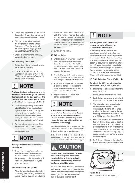
10.6 Air Adjuster Disc - 15/21 only<br />
To adjust the 15/21 air adjuster disc<br />
when downrating - See Figure 10-2<br />
1. Ensure the boiler is isolated from the<br />
electrical supply.<br />
2. Remove the burner from the boiler.<br />
3. Undo the two screws and remove the air<br />
inlet cover from the side of the burner.<br />
4. The secondary air shutter disc is<br />
factory set in position ‘C’ – i.e.<br />
with the cut-out marked C located<br />
against the die-cast boss on the fan<br />
housing - suitable for outputs of 18.3<br />
and 21 kW only. See Figure 10-2.<br />
5. Remove the screw from the centre of<br />
the air shutter disc, and re-position<br />
the disc such that the cut-out ‘B’<br />
(corresponding to 15 kW output setting<br />
– See Section 2.3) is located against the<br />
cast boss on the fan housing. Replace<br />
the screw in the centre of the air shutter<br />
disc and tighten.<br />
6. Re-fit the air inlet cover to the side of the<br />
burner and reassemble in reverse order.<br />
M<br />
L<br />
Figure 10-2:<br />
15/21 air adjuster disc at position 'C'<br />
H<br />
G<br />
F<br />
E<br />
D<br />
32