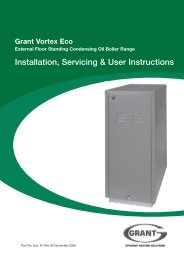
Installation & Servicing Instructions - Grant UK
Installation & Servicing Instructions - Grant UK
Installation & Servicing Instructions - Grant UK

Create successful ePaper yourself
Turn your PDF publications into a flip-book with our unique Google optimized e-Paper software.
3. Fit the ½” BSP straight end of the<br />
flexible expansion vessel hose to the<br />
tapping on the front of the waterway<br />
using a suitable thread sealant.<br />
4. Position the 12 litre expansion vessel<br />
on the front of the boiler combustion<br />
door locating the hook (on the back<br />
of the vessel) onto the uppermost<br />
handle of the combustion door.<br />
5. Fit the ¾” BSP connection of the<br />
flexible expansion vessel hose to the<br />
vessel using the black rubber washer<br />
supplied and tighten the nut.<br />
6. Push the 22 mm push-fit elbow<br />
(supplied with the boiler) onto the<br />
boiler flow pipe.<br />
7.4 26/36, 36/46 Sealed System Kit<br />
See Figure 7-6<br />
Flow connection<br />
on top of boiler<br />
Push-fit connector<br />
Automatic air vent<br />
Pressure relief valve<br />
Front<br />
of boiler<br />
7. Screw in the locking screw on the<br />
base of the bracket to secure the<br />
vessel in place.<br />
8. Fit the ¾” BSP connection of the<br />
flexible expansion vessel hose to the<br />
vessel using the black rubber washer<br />
supplied and tighten the nut.<br />
9. Remove the right hand boiler casing<br />
panel (viewed from the burner end).<br />
This panel is fixed in place by:<br />
• Two screws in the right end of the<br />
upper rear panel.<br />
• Four screws along the lower outer<br />
edge of the side panel.<br />
• Two screws at the right end of the<br />
control panel.<br />
7. Fit the pressure relief valve and<br />
automatic air vent onto the<br />
manifold pipe, then push the<br />
manifold pipe end into the 22 mm<br />
push-fit elbow on the flow pipe.<br />
Refer to Figure 7-5.<br />
8. Fit both 22 mm pump valves to the<br />
circulating pump using the sealing<br />
washers supplied.<br />
9. Fit the pump assembly to the<br />
automatic air vent/pressure relief<br />
valve assembly ensuring that the<br />
pump shaft is horizontal and the<br />
pump motor is facing towards the<br />
front of the boiler. The flow arrow<br />
on the body of the pump must<br />
face in the direction of flow away<br />
from the boiler connection.<br />
10. Fit the pressure relief valve discharge<br />
pipe to the pressure relief valve using<br />
the nut and olive supplied. Route the<br />
discharge pipe through the slot in the<br />
base of the right hand side panel.<br />
Push the panel insulation back to<br />
expose the slot.<br />
11. The circulating pump may be<br />
wired into the boiler control panel<br />
if required. Refer to Section 8.<br />
12. The pressure gauge and filling loop<br />
should be installed in a convenient<br />
position inside the building.<br />
Figure 7-6: 26/36, 36/46 pump assembly<br />
1. The kit includes the following items:<br />
• Pressure relief valve and automatic<br />
air vent.<br />
• 28 mm manifold pipe.<br />
• 16 litre expansion vessel with flexible<br />
hose and sealing washer.<br />
• Expansion vessel mounting bracket<br />
with vessel locking screw.<br />
• Filling loop kit.<br />
• Pressure gauge.<br />
• 7 m head circulating pump with 28<br />
mm gate valves.<br />
• 15 mm copper pressure relief<br />
valve discharge pipe (in two<br />
pieces with push-fit conne.<br />
2. Remove the ½” BSP black iron plug<br />
from the front of the boiler waterway,<br />
using a 3/8" drive socket wrench.<br />
3. Fit the ½” BSP straight end of the<br />
flexible expansion vessel hose to the<br />
tapping on the front of the waterway<br />
using a suitable thread sealant.<br />
4. Remove the nuts and washers from<br />
the boiler combustion door.<br />
5. Fit the vessel support bracket to the<br />
studs of the combustion door and<br />
refit the nuts and washers. Tighten to<br />
ensure an adequate seal is made.<br />
6. Position the 16 litre expansion vessel<br />
onto the support bracket in front of<br />
the boiler combustion door locating<br />
the top of the vessel behind the<br />
control panel first.<br />
Note: It will be necessary to<br />
support the control panel when<br />
the side panel is removed.<br />
10. Slacken the compression nut at the<br />
base of the flow connection pipe (on the<br />
right hand side of the boiler). Carefully<br />
rotate the flow pipe through 180° until<br />
it faces to the front of the boiler, then<br />
re-tighten the compression nut.<br />
11. Push the 28 mm push-fit connector<br />
(supplied with the boiler) onto the<br />
end of the boiler flow pipe.<br />
12. Fit the pressure relief valve and<br />
automatic air vent onto the manifold<br />
pipe, then push the manifold pipe<br />
end into the 28 mm push-fit elbow<br />
on the flow pipe. Refer to Figure 7-6.<br />
13. Remove the two screws securing the<br />
motor to the pump body. Rotate the<br />
motor through 180°, then replace and<br />
secure with the two screws. Fit both<br />
28 mm pump valves to the pump using<br />
the sealing washers supplied.<br />
14. Fit the pump assembly to the automatic<br />
air vent/pressure relief valve assembly<br />
ensuring that the pump shaft is<br />
horizontal and the pump motor is facing<br />
towards the rear of the boiler. The flow<br />
arrow on the body of the pump must<br />
face in the direction of flow away from<br />
the boiler connection.<br />
15. Fit the pressure relief valve discharge<br />
pipe to the pressure relief valve using<br />
the nut and olive supplied. Route the<br />
discharge pipe through the slot in<br />
the base of the right hand side panel.<br />
Push the panel insulation back to<br />
expose the slot.<br />
Sealed Systems<br />
21