Installation & Servicing Instructions - Grant UK
Installation & Servicing Instructions - Grant UK
Installation & Servicing Instructions - Grant UK

You also want an ePaper? Increase the reach of your titles
YUMPU automatically turns print PDFs into web optimized ePapers that Google loves.
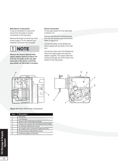
Main Burner Components<br />
It may be necessary to remove the<br />
burner from the boiler to access<br />
connections in the fuel pump.<br />
Remove the single nut at the top of the<br />
burner (using a 13 mm spanner) and<br />
withdraw the burner from the boiler.<br />
!<br />
NOTE<br />
Remove the factory fitted air inlet<br />
spigot adaptor (item) 6 in Figure 3-6<br />
from the air intake on the top right<br />
hand side of the burner and fit the<br />
grey plastic air inlet grille in its place.<br />
Burner Connection<br />
If a two pipe system is to be used refer<br />
to Section 3.2.<br />
Remove and discard the blanking plug<br />
from the inlet (suction) port of the pump.<br />
Refer to Figure 3-5.<br />
Connect the elbow of the flexible fuel<br />
hose supplied with the boiler to the inlet<br />
port.<br />
Connect the other end of the flexible fuel<br />
hose to the rigid supply line using the<br />
adaptor supplied. The supply enters the<br />
enclosure through one of the holes in the<br />
bottom of the side panels.<br />
3<br />
6<br />
2<br />
7<br />
8<br />
5<br />
4<br />
1<br />
Figure 3-6: Riello RDB burner components<br />
Oil Storage & Supply<br />
System<br />
Item<br />
1<br />
2<br />
3<br />
4<br />
5<br />
6<br />
7<br />
8<br />
Description<br />
Oil pump<br />
Control box<br />
Reset button with lock-out lamp<br />
Flange with gasket (do not remove from boiler)<br />
Air damper adjustment screw<br />
Air supply tube connection (balanced flue)<br />
Pump pressure adjustment screw<br />
Pressure gauge connection<br />
12