Arizona Geological Survey OPEN-FILE REPORT OFR 08-06
Arizona Geological Survey OPEN-FILE REPORT OFR 08-06
Arizona Geological Survey OPEN-FILE REPORT OFR 08-06

You also want an ePaper? Increase the reach of your titles
YUMPU automatically turns print PDFs into web optimized ePapers that Google loves.
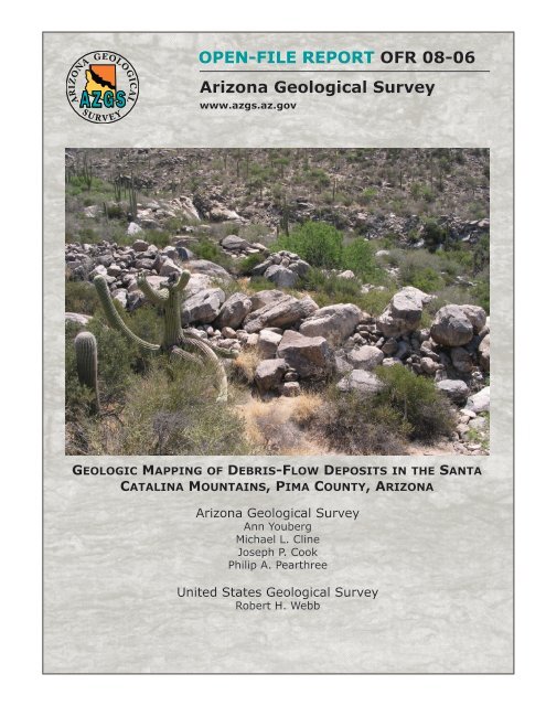
<strong>OPEN</strong>-<strong>FILE</strong> <strong>REPORT</strong> <strong>OFR</strong> <strong>08</strong>-<strong>06</strong><br />
<strong>Arizona</strong> <strong>Geological</strong> <strong>Survey</strong><br />
www.azgs.az.gov<br />
Geologic Mapping of Debris-Flow Deposits in the Santa<br />
Catalina Mountains, Pima County, <strong>Arizona</strong><br />
<strong>Arizona</strong> <strong>Geological</strong> <strong>Survey</strong><br />
Ann Youberg<br />
Michael L. Cline<br />
Joseph P. Cook<br />
Philip A. Pearthree<br />
United States <strong>Geological</strong> <strong>Survey</strong><br />
Robert H. Webb
Geologic Mapping of Debris Flow Deposits in the Santa Catalina Mountains,<br />
Pima County, <strong>Arizona</strong><br />
Open‐File Report <strong>08</strong>‐<strong>06</strong><br />
Ann Youberg<br />
Michael L. Cline<br />
Joseph P. Cook<br />
Philip A. Pearthree<br />
Robert H. Webb<br />
September 20<strong>08</strong><br />
Research supported by Pima County Regional Flood Control District, the <strong>Arizona</strong> <strong>Geological</strong><br />
<strong>Survey</strong>, and United States <strong>Geological</strong> <strong>Survey</strong>.<br />
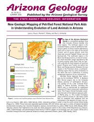
Cover Photo: Debris‐flow levees (yellow lines) along Finger Rock Wash (blue line) just downstream<br />
of the canyon mouth. Photo taken June 4, 20<strong>06</strong>, by Ann Youberg.<br />
Suggested Citation:<br />
Youberg, Ann, Cline, M. L., Cook, J. P., Pearthree, P. A., and Webb, R. H., 20<strong>08</strong>, Geologic Mapping of<br />
Debris Flow Deposits in the Santa Catalina Mountains, Pima County, <strong>Arizona</strong>; <strong>Arizona</strong> <strong>Geological</strong> <strong>Survey</strong><br />
Open‐File Report <strong>08</strong>‐<strong>06</strong>, 41 pp, 11 map sheets on CD, scale 1:6,000.
<strong>Arizona</strong> <strong>Geological</strong> <strong>Survey</strong><br />
Table of Contents<br />
ABSTRACT ..................................................................................................................................................... iv<br />
INTRODUCTION ............................................................................................................................................. 5<br />
Background ............................................................................................................................................... 5<br />
Location ..................................................................................................................................................... 5<br />
Debris flows............................................................................................................................................... 6<br />
Terminology .......................................................................................................................................... 6<br />
Initiation ................................................................................................................................................ 7<br />
Rheology ............................................................................................................................................... 8<br />
GIS‐Derived Basin Characteristics ......................................................................................................... 9<br />
METHODS ...................................................................................................................................................... 9<br />
GIS‐Derived Basin Characteristics ............................................................................................................. 9<br />
Geologic Mapping of Debris‐Flow Deposits ............................................................................................ 10<br />
Generalized Map Unit Descriptions .................................................................................................... 13<br />
Numerical Age Dating of Debris‐Flow Deposits ...................................................................................... 16<br />
Radiocarbon Dating............................................................................................................................. 16<br />
Cosmogenic Dating ............................................................................................................................. 16<br />
Sample Collection ............................................................................................................................... 17<br />
Sample Preparation ............................................................................................................................ 18<br />
Analysis of Targets .............................................................................................................................. 19<br />
RESULTS ...................................................................................................................................................... 20<br />
GIS‐Derived Basin And Stream Characteristics ....................................................................................... 20<br />
Geologic Mapping ................................................................................................................................... 23<br />
Agua Caliente‐La Milagrosa‐Molino Canyons ..................................................................................... 23<br />
i
<strong>Arizona</strong> <strong>Geological</strong> <strong>Survey</strong><br />
Soldier Canyon .................................................................................................................................... 24<br />
Gibbon Canyon .................................................................................................................................... 27<br />
Sabino and Bear Canyons .................................................................................................................... 28<br />
Esperero and Bird Canyon................................................................................................................... 29<br />
Ventana Canyon .................................................................................................................................. 30<br />
Finger Rock and Pontatoc Canyons ..................................................................................................... 31<br />
Cobblestone Canyon ........................................................................................................................... 32<br />
Pima Canyon ....................................................................................................................................... 33<br />
Pusch Canyon ...................................................................................................................................... 34<br />
Linda Vista ........................................................................................................................................... 34<br />
Numerical Age Dating ............................................................................................................................. 35<br />
Radiocarbon Dates .............................................................................................................................. 35<br />
Cosmogenic 10 Be Dates ....................................................................................................................... 35<br />
DISCUSSION ................................................................................................................................................. 37<br />
ACKNOWLEDGEMENTS ............................................................................................................................... 38<br />
REFERENCES ................................................................................................................................................ 39<br />
GEOLOGIC TIMESCALE ................................................................................................................................ 44<br />
GLOSSARY.................................................................................................................................................... 44<br />
ii
<strong>Arizona</strong> <strong>Geological</strong> <strong>Survey</strong><br />
List of <strong>Arizona</strong> <strong>Geological</strong> <strong>Survey</strong> Digital Map Series maps included on accompanying CD:<br />
Map Title<br />
Debris‐Flow Deposits at the Mouths of Agua Caliente, La Miligrosa, and Molino Canyons<br />
Debris‐Flow Deposits at the Mouth of Soldier Canyon<br />
Debris‐Flow Deposits at the Mouth of Gibbon Canyon<br />
Debris‐Flow Deposits at the Mouths of Bear and Sabino Canyons<br />
Debris‐Flow Deposits at the Mouths of Bird and Esperero Canyons<br />
Debris‐Flow Deposits at the Mouth of Ventana Canyon<br />
Debris‐Flow Deposits at the Mouths of Pontatoc and Finger Rock Canyons<br />
Debris‐Flow Deposits at the Mouth of Cobblestone Canyon<br />
Debris‐Flow Deposits at the Mouth of Pima Canyon<br />
Debris‐Flow Deposits at the Mouth of Pusch Canyon<br />
Debris‐Flow Deposits at the Mouth of Linda Vista Canyon<br />
Map Number<br />
DM‐DF‐1A<br />
DM‐DF‐1B<br />
DM‐DF‐1C<br />
DM‐DF‐1D<br />
DM‐DF‐1E<br />
DM‐DF‐1F<br />
DM‐DF‐1G<br />
DM‐DF‐1H<br />
DM‐DF‐1I<br />
DM‐DF‐1J<br />
DM‐DF‐1K<br />
iii
<strong>Arizona</strong> <strong>Geological</strong> <strong>Survey</strong><br />
ABSTRACT<br />
An extremely rare weather pattern occurred over southeast <strong>Arizona</strong> in late July 20<strong>06</strong>. This five‐day<br />
storm culminated on July 31, 20<strong>06</strong>, when the last pulse of precipitation generated record floods in<br />
several washes throughout the region, and hundreds of hillslope failures and debris flows in at least four<br />
southeastern <strong>Arizona</strong> mountain ranges. In the Santa Catalina Mountains, debris flows occurred in nine<br />
canyons, exiting or nearly exiting the mountain front in five of these canyons. Infrastructure in Sabino<br />
Canyon, a popular recreational area, was damaged, as were structures and roads in Soldier Canyon.<br />
Historically debris flows in the Santa Catalina Mountains were limited in size, and to upper elevation<br />
hillslopes. There are no known reports of debris flows from the Santa Catalina Mountains affecting<br />
developed areas in historic times. However, evidence of prehistoric debris flows are present in most<br />
canyons and associated alluvial fans along the front range of the Santa Catalina Mountains. While debris<br />
flows were previously recognized as significant hazards in <strong>Arizona</strong>’s mountains and canyons , the<br />
number and extent of debris flows from the 20<strong>06</strong> storm event was surprising.<br />
In order to begin to assess debris‐flow hazards along the Santa Catalina Mountains in Pima County, we<br />
mapped the extent and character of relatively young prehistoric debris‐flow deposits in detail at fifteen<br />
canyon mouths. Mapping was conducted on a scale of 1:6,000 using aerial photographs, detailed<br />
topography, and field relationships. Deposits were classified into relative age categories based on<br />
topographic relationships, soil development and surface characteristics of the deposits. Ages of selected<br />
debris‐flow deposits in four canyons – Soldier, Sabino, Finger Rock and Pima – were estimated using<br />
radiocarbon ( 14 C) and cosmogenic ( 10 Be) isotope methods.<br />
Evidence of past debris flows were found in all fifteen canyons. Relative age dating, corroborated by<br />
10 Be, indicates the largest and most extensive deposits in all canyons are late Pleistocene to early<br />
Holocene in age. Probable debris‐flow deposits of this age are found as much as two miles downstream<br />
from the mountain front along several of the larger washes. Younger Holocene debris‐flow deposits are<br />
much more limited in size and extent, and are found only near the mountain front. Two younger<br />
deposits were dated using 14 C. A deposit in Finger Rock Canyon was dated to 550 years before present. A<br />
deposit in Pima Canyon had a modern date.<br />
Definitive debris‐flow recurrence intervals cannot be determined for several reasons. The resolution of<br />
age dating, both numerical and relative, is not sufficient to differentiate between deposits. Debris flows<br />
are deposited in active channels thus preservation is an issue. Subsequent debris flows or large floods<br />
may destroy evidence of previous debris flows through burial or by re‐working of the deposits. Existing<br />
deposits may be the result of a single debris flow, multiple pulses from a debris flow, or deposition from<br />
multiple debris flows separated by an unknown period of time. The relatively limited younger Holocene<br />
debris‐flow deposits found in all canyons suggest that recurrence intervals for debris flows exiting the<br />
Santa Catalina Mountains are probably on the order of thousands of years. Nevertheless, events from<br />
20<strong>06</strong> show that some potential exists for debris flows to exit the mountain front into developed areas<br />
near canyon mouths.<br />
iv
<strong>Arizona</strong> <strong>Geological</strong> <strong>Survey</strong><br />
INTRODUCTION<br />
Background<br />
Debris‐flow activity in the Santa Catalina Mountains in July 20<strong>06</strong> dramatically illustrated the potential for<br />
sizable debris flows to exit canyons along the mountain front and the potential for adverse impacts to<br />
properties near canyon mouths. The purpose of this study was to map the extent of prehistoric debris‐flow<br />
deposits at the mouths of selected Santa Catalina Mountain canyons in eastern Pima County. <strong>Arizona</strong><br />
<strong>Geological</strong> <strong>Survey</strong> (AZGS) geologists mapped the extent of latest Pleistocene to Holocene debris‐flow<br />
deposits along channels at the mouths of 15 canyons. In late 2007 the scope of work was expanded to<br />
include mapping of modern (20<strong>06</strong>) debris‐flow deposits in Soldier Canyon, and to delineate the<br />
downstream extent of these deposits in other canyons. United State <strong>Geological</strong> <strong>Survey</strong> (USGS) geologists<br />
collected wood and rock samples from selected paleodebris‐flow deposits to date deposit‐ages using<br />
radiocarbon and cosmogenic dating techniques. This report summarizes our findings and describes the<br />
mapped debris‐flow deposits depicted on accompanying map sheets.<br />
Debris flows can be triggered by rare, extreme precipitation events when soils with high antecedent<br />
moisture conditions receive prolonged, and sometimes intense precipitation resulting in failure of<br />
saturated soil (Anderson and Sitar, 1995; Wieczorek and Glade, 2005). Evidence of geomorphic<br />
responses to extreme precipitation events, such as remnant debris‐flow deposits, can be found<br />
throughout southern <strong>Arizona</strong>. Potential geologic hazards associated with numerous, coincident debris<br />
flows, however, were not fully appreciated prior to July 20<strong>06</strong>. During the last week of July, southern<br />
<strong>Arizona</strong> experienced five consecutive days of early morning storms generated from monsoonal moisture<br />
mixing with a persistent low‐pressure system centered over northwestern New Mexico (Magirl and<br />
others, 2007). These increasingly wet storms culminated on July 31, 20<strong>06</strong>, when the last pulse of rain fell<br />
on already saturated watersheds. Floods of record occurred in several washes throughout the region,<br />
and hundreds of hillslope failures and debris flows were generated in at least four southeastern <strong>Arizona</strong><br />
mountain ranges (Pearthree and Youberg, 20<strong>06</strong>). While debris flows were previously recognized as<br />
significant hazards in <strong>Arizona</strong>’s mountains and canyons (Wohl and Pearthree, 1991; Melis and others,<br />
1997; Pearthree, 2004), the number and extent of debris flows from the 20<strong>06</strong> storm event was<br />
unexpected.<br />
Location<br />
The 20<strong>06</strong> Santa Catalina Mountain debris flows occurred in response to extreme, prolonged<br />
precipitation, with debris flows exiting or nearly exiting the mountains in four southeastern canyons:<br />
Soldier, Gibbon, Sabino, and Bird. Canyons farther west along the south side of the Santa Catalina<br />
Mountains did not have debris flows, but abundant evidence exists of past debris flows near canyon<br />
mouths. AZGS geologists mapped debris‐flow deposits at the mouths of all major canyons on the south<br />
side of the Santa Catalina Mountains: Agua Caliente, La Milagrosa, Molino, Soldier, Bear, Sabino, Bird,<br />
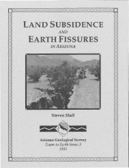
Esperero, Ventana, Pontatoc, Finger Rock, and Pima Canyons (Figure 1). Four smaller, informally named<br />
canyons were also mapped: Linda Vista Canyon on the northwest side of Pusch Ridge, Pusch Canyon just<br />
west of Pima Canyon, Cobblestone Canyon just west of Finger Rock Canyon, and Gibbon Canyon<br />
between Bear and Soldier Canyons. Gibbon Canyon is the only smaller, informally named canyon that<br />
had 20<strong>06</strong> debris‐flow activity.<br />
5
<strong>Arizona</strong> <strong>Geological</strong> <strong>Survey</strong><br />
Figure 1. Location of study canyons. Map sheets outlined in yellow; letter corresponds to Digital Map<br />
Series Debris Flow Map Number (DM‐DF‐1_). Maps are included on accompanying CD.<br />
Debris flows<br />
Debris flows are triggered when hillslope soils become saturated and destabilize (De Wrachien, 20<strong>06</strong>),<br />
resulting in mass failure. This typically happens after prolonged or particularly intense rainfall. Debris<br />
flows vary widely in size and volume and can be extremely destructive. This section provides a review of<br />
debris‐flow terminology, initiation, and rheology (deformation and behavior of matter in a flow); and<br />
background information with respect to influences of basin characteristics on formation of debris flows.<br />
Terminology<br />
Debris‐flow terminology must be carefully defined because of conflicting usages in the literature. Many<br />
terminology issues are with respect to classification of flows, and scale of initiating failures and flows.<br />
Floods, hyperconcentrated flows, and debris flows are differentiated by sediment concentration and<br />
flow rheology (Pierson and Costa, 1987; Pierson, 2005b). Debris flows are sediment‐rich slurries at one<br />
end of a continuum with water flows (floods) at the other end, and hyperconcentrated flows in the<br />
middle. Flood flows typically contain less than 40% sediment by volume and are Newtonian flows<br />
(Pierson and Costa, 1987). Suspended sediment in floods consists of clay, silt, and sometimes sand, with<br />
gravel generally transported as bedload. Hyperconcentrated flows have around 40‐60% sediment by<br />
volume and sufficient interaction between grains to keep sediment in suspension as long as flow<br />
velocities are maintained (Pierson, 2005b). Deposits from both flood and hyperconcentrated flows<br />
exhibit some sorting by grain size (Pierson, 2005a). Debris flows contain more than 60% sediment by<br />
volume and consist of sediment‐rich fluid matrix and coarse particles. The matrix of a debris flow is<br />
composed of clay, silt, and sand in suspension and is driven by high pore pressure. The coarse particles,<br />
which are influenced by frictional and gravitational forces, interact with the matrix and each other to<br />
prevent particles from settling even at low velocities. Hence, debris‐flow deposits exhibit minimal<br />
sorting (Iverson and Vallance, 2001; Pierson, 2005b).<br />
6
<strong>Arizona</strong> <strong>Geological</strong> <strong>Survey</strong><br />
The term “mud flow” is sometimes used synonymously with “debris flow” (e.g. Federal Emergency<br />
Management Agency, 20<strong>08</strong>), or to describe a flow with 0‐20% coarse clasts and a soft, remoldable clay<br />
matrix with high plasticity and liquid limit values (Hungr, 2005). However, the term “mud” has geologic<br />
and compositional implications, which is why Pierson and Costa (1987) recommend disregarding the<br />
term. Current research describes debris flows as two‐phased, non‐Newtonian flows dominated by<br />
coarse‐particle interactions (Iverson, 1997). Thus, use of the term “mud flow” is confusing and<br />
unnecessary.<br />
Debris flows can be triggered by different types and sizes of slope failures, often referred to as<br />
landslides. Some researchers use the term landslide to describe large, deep‐seated rotational or<br />
translational mass movements (Glenn and others, 20<strong>06</strong>), while other researchers apply no scale to the<br />
term and use it for all sizes and types of slope failures (Terranova and others, 2007). Shallow landslides<br />
are the most common trigger of debris flows (Iverson and others, 1997), especially in areas that have<br />
not been subject to recent fire. Generally, the term landslide‐induced debris flow is used to describe a<br />
shallow translational failure of thin soil over bedrock that liquefies and transforms into a debris flow<br />
(Iverson and others, 1997; Cannon and others, 2002; Santi and others, 2007). This description applies to<br />
the 20<strong>06</strong> debris flows in the Santa Catalina Mountains.<br />
Debris flows have three zones ‐ initiation, transport and deposition ‐ where different processes occur<br />
(Hungr, 2005) (Figure 2). Initiation zones are where slope failures occur, usually identified by distinct<br />
head scarps, and debris flows are generated. Once initiated, debris flows travel downslope through<br />
existing channels. The character of a debris flow changes in time and space as it travels downslope.<br />
Debris flows commonly move in surges led by a coarse‐boulder front (head), followed by a liquefied<br />
slurry (body), and a more watery tail which is often a hyperconcentrated flow (Hungr, 2005). Levees,<br />
which confine the flow, may be deposited anywhere along the channel due to longitudinal sorting<br />
(Hungr, 2005), but are most obvious in areas with less lateral topographic confinement. Debris‐flow<br />
volumes can change significantly during downslope movement as scouring or deposition occurs (Iverson<br />
and Vallance, 2001). Debris‐flow deposition occurs in areas where lateral confinement decreases and/or<br />
channel slope decreases. Depositional areas are often alluvial fans located at the mouths of drainages.<br />
Initiation<br />
Hydrological conditions that can trigger debris flows include prolonged or intense convective rainfall<br />
(Webb and others, 2005), rain‐on‐snow events (Meyer and others, 2001; Lenzi, 20<strong>06</strong>), or rainfall on<br />
recently burned areas (Cannon and Gartner, 2005). In <strong>Arizona</strong>, debris flows have been generated by<br />
dissipating tropical storms, prolonged winter storms, intense convective summer storms, and postwildfire<br />
summer storms. Debris flows usually initiate on steep slopes between 20 o and 45 o (Hungr, 2005)<br />
but have initiated on slopes as low as 11° (Lenzi, 20<strong>06</strong>). Nearly all of the 20<strong>06</strong> debris flows in the Santa<br />
Catalina Mountains initiated on steep slopes (Webb and others, 20<strong>08</strong>).<br />
Debris flows in undisturbed (unburned) areas are triggered when soils become saturated and<br />
destabilize. Soil pore pressure in saturated soils increases and shear strength decreases to a critical point<br />
at which failure occurs, rapidly mobilizing the soil mass into a viscous slurry through liquefaction or<br />
dilatancy (Costa, 1984). As described above, the initial failure can be rotational or translational (Costa,<br />
1984). Debris flows can also form in channels when sediments are mobilized by runoff (Costa, 1984).<br />
Debris flows formed by mobilized channel sediment, called progressive sediment bulking, have most<br />
often been noted following wildfires (Wohl and Pearthree, 1991; Cannon, 2001; Santi and others, 20<strong>08</strong>).<br />
7
<strong>Arizona</strong> <strong>Geological</strong> <strong>Survey</strong><br />
Rheology<br />
Figure 2. Examples from Sabino Canyon of initiation, transport and deposition zones.<br />
Rheology describes the relationship between flow stress and strain rates and how the flow deforms. The<br />
seminal work on debris‐flow rheology was conducted by Bagnold (1954) in experiments exploring shear<br />
and normal stresses in mixtures of non‐cohesive, neutrally buoyant grains in a liquid matrix. For many<br />
years, based mainly on this work, debris flows were modeled using a single, fixed rheology to describe<br />
matrix flow behavior, neglecting the influences of grain‐interactions. However, by using non‐cohesive,<br />
neutrally buoyant grains, Bagnold masked the gravitational forces on grain‐to‐grain stresses (Takahashi<br />
and others, 1997; Iverson and Vallance, 2001). Recent research comparing field observations, laboratory<br />
measurements, and numerical modeling show debris flows with significant amounts of coarse clasts can<br />
not be sufficiently modeled using a one‐phase rheology approach, regardless of matrix clay content<br />
(Sosio and others, 2007). Data show grain‐to‐grain interactions of coarser material in an interstitial fluid<br />
are best represented by a two‐phase granular approach where both pore pressure and frictional effects<br />
are represented (Sosio and others, 2007). Most researchers now view debris flows as a two‐phased flow<br />
composed of a finer‐grained matrix influenced by pore pressure and a coarse‐grained fraction<br />
influenced by frictional and gravitational forces (Iverson, 1997; Takahashi and others, 1997; Iverson and<br />
Vallance, 2001; Sosio and others, 2007).<br />
Instead of rheological equations, Iverson and Vallance (2001) use the Coulomb equation to describe flow<br />
behavior. This equation has no dependence on stress rate, but maintains proportionality between shear<br />
and normal stresses while satisfying conservation of momentum (Iverson and Vallance, 2001). Grainfluid<br />
mixtures have unsteady flow characteristics due to fluctuating states, which affects flow patterns.<br />
8
<strong>Arizona</strong> <strong>Geological</strong> <strong>Survey</strong><br />
The flow tends to move as a rigid plug‐like flow if pore‐pressure and intergranular interactions are low<br />
and is more fluid‐like when these variables are high (Iverson and Vallance, 2001). Both pore pressure<br />
and granular interactions change as the debris flow moves downslope. As a result, flow depth fluctuates<br />
to accommodate volumetric changes due to the affects of grain‐to‐grain interactions and variable porepressure<br />
(Iverson and Vallance, 2001). These unsteady flow characteristics can be seen in the anatomy<br />
of a debris flow. The abrupt, coarse‐grained surge head, dominated by Coulomb friction, is followed by a<br />
more fluid body and tail with fluctuating pore‐fluid pressure and intergranular stresses (Iverson and<br />
Vallance, 2001).<br />
GIS‐Derived Basin Characteristics<br />
Many models have been developed to assess debris‐flow behavior (Iverson, 1997; Iverson and others,<br />
2005), to estimate debris‐flow erosion (Stock and Dietrich, 20<strong>06</strong>), and to predict debris‐flow hazards<br />
(O'Brien and others, 1993; Wilford and others, 2004; Cannon and Gartner, 2005; Gartner and others,<br />
2005). These models address debris flows generated from extreme precipitation, rapid snow melt, or as<br />
a result of disturbance due to land‐use change, such as logging or wildfires. Many models use basin<br />
morphometric parameters (basin size, shape, and gradient) to evaluate the probability of debris‐flow<br />
occurrence and potential volume of material generated (Wilford and others, 2004; Gartner and others,<br />
2007).<br />
Basin morphometric parameters are a function of basin contributing area, basin relief, hillslope<br />
processes, geology, and climate (Tucker and Bras, 1998; Wohl, 2000). Basins with higher relief and<br />
higher‐gradient streams have more capacity to transport larger clasts and typically have greater<br />
quantities of available sediment than low‐relief basins with lower‐gradient streams (Montgomery and<br />
Buffington, 1997). Recent work suggests that basin area, average basin gradient, aspect, relief ratio,<br />
Melton Ratio, and length of watershed are potential indicators of debris‐flow prone basins (Wilford and<br />
others, 2004; Cannon and Gartner, 2005; Rowbotham and others, 2005). The relief ratio and Melton<br />
Ratio are both measurements of basin ruggedness. The relief ratio describes basin topographic relief<br />
with respect to the length of the watershed: the Melton Ratio describes basin relief with respect to the<br />
square root of basin area. While modeling and basin analysis were not part of this study, and all mapped<br />
canyons have evidence of past debris‐flow activity, a brief examination of basin and channel<br />
morphometrics from the study canyons may provide insight regarding potential basin response to a<br />
given rainfall sequence.<br />
METHODS<br />
GISDerived Basin Characteristics<br />
Basin and stream measurements were derived using ESRI ArcMap 9.2 spatial analysist and an ArcMap<br />
extension called Terrain Analysis Using Digital Elevation Models (TauDEM) (Tarboton, 2005). GIS tools<br />
extract basin measurements such as area, elevation, orientation, slope gradient, and basin length.<br />
Stream networks were derived for each canyon using TauDEM, which calculates flow direction and<br />
accumulation for each cell in a digital elevation model (DEM). The user selects a threshold flow<br />
accumulation value to extract stream networks. For example, a threshold flow accumulation value of<br />
100 means that for any given cell to become part of the stream network at least 100 upslope cells must<br />
drain into that cell. Several methods have been developed to select appropriate threshold values for<br />
stream network extraction from a DEM (Tucker and others, 2001; Tarboton, 2005). One accepted<br />
9
<strong>Arizona</strong> <strong>Geological</strong> <strong>Survey</strong><br />
method, used in this study, is to select values using trial and error to derive a network as similar as<br />
possible to printed USGS topologic maps (scale 1:24000) (Tarboton, 2005). Stream networks were<br />
derived using an accumulation threshold of 1000 cells; an area slightly less than 25 acres. The derived<br />
stream network shapefile was imported into a geodatabase and placed into a geometric framework,<br />
using ArcGIS tools, to extract stream profiles and calculate average stream gradients.<br />
Basin and channel morphometric parameters were derived from a single outlet point for each study<br />
canyon. Outlet points were created and entered into a GIS point shapefile by selecting a stream network<br />
cell where the wash exits the mountain front. The basin consists of all upslope cells that drain through<br />
the outlet point.<br />
Geologic Mapping of DebrisFlow Deposits<br />
Debris‐flow deposits were mapped using a combination of 1960 (scale 1:9,000) and 2007 (scale<br />
1:12,000) black‐and‐white aerial photographs from Cooper Aerial <strong>Survey</strong>s; 2002 Pima County color<br />
digital orthophoto imagery; and extensive field observations. Each canyon was walked as far<br />
downstream as debris‐flow or likely debris‐flow deposits were encountered, although in some areas<br />
development has masked or substantially modified debris‐flow deposits. Debris‐flow deposits were also<br />
mapped well upstream of the Coronado National Forest boundary. Field observations were recorded<br />
with GPS coordinates (several meter positional uncertainty), digital photographs, and notes. ESRI<br />
ArcMap GIS software was used to combine field data and aerial photographic information to delineate<br />
debris‐flow deposits as accurately as possible at a scale of 1:6,000.<br />
Debris‐flow deposits were differentiated by relative age using topographic relationships, surface<br />
characteristics of boulders, and soil characteristics. Multiple generations of relatively young (Holocene<br />
to latest Pleistocene) debris‐flow deposits exist in each drainage, but the number of separate debrisflow<br />
deposits mapped represents a minimum number of debris flows for several reasons:<br />
o<br />
o<br />
o<br />
o<br />
Each mapped deposit may have formed as a result of multiple pulses from single flow or<br />
numerous successive debris flows.<br />
Not all Holocene debris‐flow deposits are preserved due to the active nature of the channel<br />
environment and erosion and deposition in subsequent debris flows.<br />
Many debris‐flow deposits are likely overlain by more recent deposition and are not visible at<br />
the surface (Figure 3).<br />
Bouldery sections of the channel can be attributed to either reworked debris‐flow sediments or<br />
heavily eroded debris‐flow lobes.<br />
Relative ages of debris‐flow deposits were estimated using soil characteristics when present, weathering<br />
characteristics of large clasts (boulders and cobbles), and position in the landscape (Birkland, 1999;<br />
Menges and others, 2001). Clasts in older debris‐flow deposits generally exhibited darkened weathering<br />
rinds, some degree of oxidation (orange surface patina), fracturing and splitting, and in some deposits,<br />
slight to moderate burial. In contrast, clasts in younger deposits had no weathering rinds and weak to<br />
non‐existent surface patinas, and thus were brighter and fresher looking, with little to no soil<br />
accumulation or fracturing.<br />
The general labeling scheme used to place mapped debris‐flow deposits in relative age order is<br />
described below. Debris‐flow deposits cannot be directly correlated between canyons as we do not have<br />
sufficient age control, but various deposits in each canyon were classified by estimated age. Numbers<br />
10
<strong>Arizona</strong> <strong>Geological</strong> <strong>Survey</strong><br />
indicate levels of relative age distinctions between debris‐flow deposits of broadly similar ages. The<br />
generalized labeling scheme presented below was modified as needed for each canyon.<br />
Figure 3. An example from Soldier Canyon of fresh 20<strong>06</strong> debris‐flow deposits (yellow circle) overlying<br />
older undisturbed deposits (blue circles).<br />
Debris‐flow deposits often exhibit characteristic morphology based on depositional processes. Levees<br />
are linear aggregations of boulders and cobbles that form along lateral margins of debris flows during<br />
downslope transport (Figure 4). Snouts are wider, lobate aggregations of boulders and cobbles that form<br />
where debris flows terminate (Figure 5). When characteristic morphology was identified during field<br />
mapping or through aerial photographic interpretation, debris‐flow deposits were classified as either<br />
levee (subscript L) or snout (subscript S). Deposits of uncertain morphology, due to either partial burial<br />
or disturbance, were undifferentiated (no subscript L or S). Two other types of coarse cobble‐ and<br />
boulder‐dominated deposits, found some distance from the mountain front, were also classified based<br />
on morphology. Boulder‐bar (B) deposits exhibited some debris‐flow characteristics but could not be<br />
clearly identified to due to partial burial or disturbance of deposits. Coarse, unsorted cobble and boulder<br />
(C) deposits were exposed along channel banks bottoms, and interpreted as older debris‐flow deposits<br />
reworked by either high discharge fluvial processes or secondary debris flows. Both B and C deposits<br />
were found at the lower extent of mapped debris‐flow deposits. Many of the areas mapped have been<br />
disturbed to some degree by development. In some areas older debris‐flow deposits evident in earlier<br />
aerial photographs have been obscured by recent development.<br />
11
<strong>Arizona</strong> <strong>Geological</strong> <strong>Survey</strong><br />
Figure 4. An example of a well‐preserved levee deposit in Esperero Canyon. This deposit was mapped as<br />
unit YI (see text below).<br />
Figure 5. An example of a well‐preserved snout deposit from Pima Canyon. This deposit was mapped as<br />
Y1 (see text below).<br />
12
<strong>Arizona</strong> <strong>Geological</strong> <strong>Survey</strong><br />
Generalized Map Unit Descriptions<br />
In deposits that are identifiable as either levees or snouts, the type of deposit denoted by subscript<br />
letter:<br />
L = Debris‐flow levees<br />
S = Debris‐flow snouts<br />
Preliminary age estimates for various deposits, from oldest to youngest, are in parentheses. Soils colors<br />
are based on the Munsell Soil Color Chart.<br />
I – Pleistocene debris‐flow deposits, undifferentiated. Debris‐flow deposits that are either the highest,<br />
most weathered deposits in the landscape and have clearly reddened soil (5YR), or are indurated<br />
deposits that have been buried by younger debris flows and exposed through subsequent erosion.<br />
YI‐ Older debris‐flow deposits (latest Pleistocene to early Holocene). Debris‐flow deposits that are<br />
spatially removed from active fluvial systems, either high‐standing or laterally separate from younger<br />
deposits. Clasts are slightly to moderately weathered, lightly to moderately stained by oxidation, and<br />
commonly exhibit fracturing and splitting. Surfaces between boulders are slightly reddened (7.5YR), and<br />
in some areas clasts are partially to almost completely buried by finer deposits. Clasts from disturbed<br />
deposits often have thin, discontinuous carbonate coatings. In some areas YI deposits can be further<br />
classified into two levels:<br />
YI 1 ‐ Highest standing debris‐flow deposits.<br />
YI 2 ‐ Debris‐flow deposits of similar age inset 3‐7 feet (ft [1‐2 m]) below YI 1 deposits.<br />
Y1 – Intermediate debris‐flow deposits (early to middle Holocene). Debris‐flow deposits found 7‐10 ft<br />
(2‐3 m) above active washes near the mountain front and 3‐7 ft (1‐2 m) above the active washes farther<br />
away from the mountain fronts. Y1 deposits typically are fairly extensive on the upper portions of fans,<br />
but are confined to valley bottoms along incised drainages farther out from the mountain front. Clasts<br />
generally are slightly weathered, with light surface oxidation and little rock fracturing. Clasts in Y1<br />
deposits may be slightly buried from initial deposition and subsequent abandonment, soil accumulation,<br />
or overbank deposition. Soil color varies from gray (10YR) to brown (7.5YR).<br />
Y2 – Young debris‐flow deposits (middle to late Holocene). Debris‐flow deposits found along banks and<br />
terraces of active washes, typically 3‐7 ft (1‐2 m) above channel floors (Figure 6). Fine grained matrix<br />
sediments are generally absent from Y2 deposits leaving only clasts that appear fresh and unweathered.<br />
Vegetation typically is sparse on boulder levees and snouts, but deposits generally have some mature<br />
vegetation growing in them.<br />
Y3 – Very young debris‐flow deposits (latest Holocene to modern). Debris‐flow deposits found in and<br />
adjacent to active channels near the mountain front and on upper portions of active alluvial fans (Figure<br />
7). Clasts are fresh and unweathered. Vegetation typically is sparse on boulder levees and snouts. Y3<br />
deposits are commonly located in or immediately adjacent to stream channels and are subject to<br />
reworking by fluvial processes, so the extent and characteristics of deposits may change with successive<br />
flow events.<br />
Y4‐ Modern debris‐flow deposits (20<strong>06</strong>). Debris‐flow deposits in Soldier Canyon emplaced in 20<strong>06</strong><br />
(Figure 8). The decision to map these modern deposits occurred in late 2007, after significant channel<br />
alterations occurred on Soldier fan adjacent to the Mount Lemmon Short Road. The location and extent<br />
13
<strong>Arizona</strong> <strong>Geological</strong> <strong>Survey</strong><br />
of the 20<strong>06</strong> debris‐flow deposits adjacent to the Mount Lemmon Short Road are based mainly on<br />
photographs taken by the USGS and AZGS in August and September of 20<strong>06</strong>. Deposits denoted with a<br />
question mark (Y4?) have debris‐flow characteristics but may be flood‐related or re‐worked.<br />
Figures 6 and 7. Figure 6 (left) An example of a boulder levee (unit Y2) from Linda Vista canyon. Figure 7<br />
(right) An example of a debris‐flow deposit (unit Y3) in Pontatoc Wash.<br />
Figure 8. 20<strong>06</strong> debris‐flow deposits in Soldier Wash upstream of the Mount Lemmon Short Road. Yellow<br />
lines highlight boulder snout deposited after, and on top of, an earlier pulse that likely plugged the<br />
bridge. Blue arrows show direction of flow. Photo: P.G. Griffiths, Sept. 12, 20<strong>06</strong> (see Solder Canyon<br />
discussion below).<br />
14
<strong>Arizona</strong> <strong>Geological</strong> <strong>Survey</strong><br />
B – Boulder‐bar deposits. Elongate cobble and boulder dominated deposits. B deposits resemble debrisflow<br />
levees but are often partially buried or possibly reworked by fluvial processes (Figure 9). B deposits<br />
are often inundated by fine sediments either from initial deposition and subsequent abandonment, soil<br />
accumulation, or overbank deposition. B deposits were used to define downstream extent of paleodebris‐flow<br />
deposits in several canyons.<br />
Figure 9. An example of a boulder deposits (unit B) in Pima Canyon, south of Ina Road.<br />
C – Coarse cobble and boulder deposits. Coarse cobble and boulder dominated deposits derived from<br />
reworked debris‐flow deposits. Found in channel bottoms or forming channel banks (Figure 10). These<br />
deposits generally do not exhibit sorting when viewed in channel banks, but also do not exhibit defining<br />
debris‐flow deposit characteristics. C deposits probably represent winnowed and reworked debris‐flow<br />
deposits by fluvial processes.<br />
Figure 10. An example of a C deposit in Pima Wash south of Ina Road. Note carbonate coatings. Some C<br />
deposits had clasts with carbonate coatings while others did not. Some carbonate coatings are probably<br />
a result of shallow ground water and may not be a reliable indicator of age.<br />
15
<strong>Arizona</strong> <strong>Geological</strong> <strong>Survey</strong><br />
Numerical Age Dating of DebrisFlow Deposits<br />
Radiocarbon Dating<br />
We used 14 C (radiocarbon) dating techniques to determine ages for recent debris flows in Finger Rock<br />
and Pima Canyons. 14 C is a radioactive isotope of carbon that is produced in the atmosphere from<br />
cosmogenic spallation reactions with 16 O and 14 N (Gosse and Phillips, 2001). 14 C accumulates in living<br />
material in equilibrium with atmospheric 14 C concentrations through respiration and absorption of CO 2<br />
(plants) or consumption of organic material containing 14 C (animals). Beginning with the advent of<br />
above‐ground testing of hydrogen bombs in 1952, production rates for 14 C in the atmosphere greatly<br />
increased, providing the tool of post‐bomb 14 C ages that potentially are accurate to months (Ely and<br />
others, 1992); at present (20<strong>08</strong>), production rates of 14 C are essentially at pre‐testing levels, although<br />
burning of fossil fuels dilutes the atmospheric concentration of 14 C with stable 12 C and 13 C atoms. 14 C has<br />
a half‐life of about 5,200 years and has long been used for age dating of geologic deposits bearing<br />
organic material that was deposited in association with sediments (Libby and others, 1949). The organic<br />
material collected for 14 C age dating was found in association with debris‐flow deposits, either as fine<br />
twigs trapped between boulders in such a way as they could only have been transported in the debris<br />
flow, or plants that were killed and trapped in debris‐flow deposits. All sample preparation and analyses<br />
were performed at Geochron Laboratories in Billerica, Massachusetts, using standard techniques<br />
(http://www.geochronlabs.com/14c.html).<br />
Cosmogenic Dating<br />
Numerous cosmogenic isotopes are produced in rocks and minerals exposed at the Earth’s surface<br />
(Gosse and Phillips, 2001). For quartz‐rich rocks, such as granites in the Santa Catalina Mountains, the<br />
typical isotopes used for cosmogenic dating are beryllium ( 10 Be) and aluminum ( 26 Al). Because this type<br />
of rock typically has a high, non‐cosmogenic aluminum content but essentially no beryllium content<br />
(Gosse and Phillips, 2001), we excluded 26 Al from our measurements of latest Pleistocene and Holocene<br />
debris‐flow deposits.<br />
We used cosmogenic dating of debris‐flow deposits to attempt to verify and expand the relative agedating<br />
assessments. This technique has long been used to date debris‐flow deposits, which are difficult<br />
to numeric age‐date otherwise (Bierman and others, 1995; Cerling and others, 1999; Webb and others,<br />
1999). Cosmogenic dating, in its simplest usage, reflects the amount of time a rock or mineral has been<br />
exposed at the Earth’s surface to cosmic ray bombardment. Cosmogenic rays penetrate rocks to a depth<br />
of about 3 ft (1 m) for measurable production of most cosmogenic isotopes, and the production rate<br />
decays in an approximate exponential fashion with depth; rocks below 7 ft (2 m) depth are essentially<br />
shielded from cosmic rays and have negligible production of cosmogenic isotopes prior to debris‐flow<br />
transport and exposure at the debris‐flow surface. For all depths, muon emissions are an important<br />
source of 10 Be and can be more than 4% of the total production rate; however, this source of 10 Be can be<br />
corrected easily (Balco and others, 20<strong>08</strong>). The total concentration of a cosmogenic nuclide (i.e., 10 Be) in a<br />
rock/mineral is a combination of 10 Be accumulated since emplacement of the rock in a landform of<br />
interest (i.e., a debris‐flow deposit) plus any 10 Be that may have accumulated in the rock before<br />
deposition in the new landform. One of the key assumptions in using cosmogenic dating as a numerical<br />
dating technique is that any sampled rock is either assumed to have been shielded (no prior exposure<br />
history). Corrections can be made using depth profiles and/or amalgamation samples to correct<br />
inherited nuclide from a prior exposure history (e.g., Anderson and others, 1996; Wolkowinsky and<br />
16
<strong>Arizona</strong> <strong>Geological</strong> <strong>Survey</strong><br />
Granger, 2004). Thickness of the sample, as well as its shielding from low‐angle cosmic rays by nearby<br />
rocks or cliffs, is an important value for converting an isotopic concentration to a surficial age.<br />
Cosmogenic 10 Be, a radioactive isotope with a useful lifetime of 2.2 million years, is dominantly created<br />
by spallation reactions resulting from cosmic‐ray collisions with either 28 Si or 16 O in a quartz molecule<br />
(SiO 2 ). The production rates of 10 Be atoms in quartz range from 4.74 to 6.4 atoms/g/yr when normalized<br />
to high latitude and sea level with various scaling methods (Gosse and Phillips, 2001) Production rates<br />
vary with elevation, latitude, and longitude; in particular, they increase with elevation and latitude.<br />
Longitude helps locate the samples geographically, so as to account for variations in atmospheric<br />
pressure; if in place over long periods of geologic time, low pressure weather systems increase<br />
production rates (Balco and others, 20<strong>08</strong>). An on‐line calculator developed for the CRONUS‐Earth<br />
project is useful for estimating the production rate of 10 Be and related 10 Be exposure ages for the<br />
southern Santa Catalina Mountains (Balco and others, 20<strong>08</strong>; http://hess.ess.washington.edu/math).<br />
Naturally occurring beryllium typically is not found in significant quantities in quartz‐bearing rocks that<br />
are not ore bearing. Contamination from cosmogenically produced 10 Be is possible, however, because<br />
the production rate in the atmosphere is higher than in rocks. 10 Be created in the atmosphere is<br />
transferred to the Earth’s surface in rainfall and can be deposited in rocks along cracks or mineral<br />
boundaries. Therefore, 10 Be created in the atmosphere is a contaminant that must be removed from<br />
samples prior to analysis. Because 10 Be created in situ in quartz is the measurement goal, other<br />
mineralogic components of granites must be removed as well, including (but not limited to) micas and<br />
feldspars.<br />
Sample Collection<br />
We identified surfaces comprised of debris‐flow deposits along the channels just downstream from<br />
Linda Vista, Pima, Finger Rock, Rattlesnake, and Soldier Canyons. These surfaces were on lands<br />
administered by the U.S. Forest Service and just upstream from private lands. Samples collected from<br />
Pima, Finger Rock, and Soldier Canyons were processed for cosmogenic ages; samples from the other<br />
drainages, and extra samples from the three principal drainages, were archived for potential later<br />
analyses. In addition to samples from these three canyons, we collected and analyzed samples from two<br />
extremely large boulders transported during the Ocho Grande debris flow, which occurred from an<br />
unnamed tributary at Tram Stop 8 in Sabino Canyon (Webb and others, 20<strong>08</strong>).<br />
We collected samples from surfaces that were arranged vertically (stratigraphically) above the thalweg<br />
of the primary channels draining these canyons and had sufficient horizontal extent to be mappable. For<br />
example, see representative cross sections for Pima, Finger Rock and Soldier Canyons appear in Figure<br />
11. For each surface, we selected a minimum of three boulders with the following characteristics: (1) the<br />
boulders had similar amounts of weathering and (or) desert varnish and appeared to be representative<br />
of primary deposition on the surface; (2) the boulders were stable and did not appear to have rolled<br />
following deposition; (3) the boulders had a relatively high amount of quartz with low feldspar and mica;<br />
(4) the top of the boulders either were at, or protruded above, the surrounding surface with minimal<br />
shielding from cosmic ray bombardment; and (5) the top of the boulders either were relatively level or<br />
had a measurable slope that would allow estimation of self shielding. Using a hammer and chisel, we<br />
collected 1.5 to 2.5 in. (3.75‐6.25 cm) from the tops of these boulders. We collected 3‐4 samples<br />
chiseled from boulders at each terrace level and also collected a whole boulder for possible future<br />
analysis.<br />
17
<strong>Arizona</strong> <strong>Geological</strong> <strong>Survey</strong><br />
Figure 11. Cross‐sections of levees sampled for cosmogenic dating from Pima Canyon (map DM‐DF‐1I),<br />
Finger Rock Canyon (map DM‐DF‐1G) and Soldier Canyon (map DM‐DF‐1B). Labels L1 – L5 are<br />
topographic positions associated with the sample numbers in Table 2. Refer to maps for 10 Be sample<br />
locations and ages, and to compare with relative geomorphic ages.<br />
Sample Preparation<br />
We selected three boulder samples from each site to analyze for 10 Be concentrations and to calculate<br />
exposure ages (see Table 2, Results Section). All of the samples we selected were chiseled pieces from<br />
the tops of boulders; no whole‐rock samples were processed. We used a standard laboratory procedure<br />
to produce 10 Be targets for accelerator mass spectrometer analysis (Bookhagen, 2007) with some<br />
modifications as noted below.<br />
Using a jaw crusher and a Biko grinder, we reduced the samples to sand‐sized particles (< 2 mm) or finer<br />
diameter. We sieved the processed samples using disposable nylon sieves to obtain a particle fraction<br />
between 250 and 500 μm size for further analysis. Other size fractions were saved for potential future<br />
analyses, and in one case a saved fraction was processed. Our methods yielded a sample of 500 – 1000<br />
grams (g) for extraction of cosmogenic 10 Be.<br />
We used approximately 3L of 6N (1:1) HCl (hydrochloric acid) to soak the sample at 60º C for a minimum<br />
of 6 hrs (usually overnight) to remove fine particles, carbonates, and some Fe. After rinsing, drying, and<br />
18
<strong>Arizona</strong> <strong>Geological</strong> <strong>Survey</strong><br />
weighing of the remaining particles, on average 3% of the sample was removed at this step. We then<br />
used a 5% mixture of HF (hydrofluoric acid) and HNO 3 (nitric acid) to begin the process of etching quartz<br />
grains and dissolution of other minerals using a typical sample‐to‐liquid ratio of 30 grams/liter (g/L) and<br />
a temperature of 50‐60º C for 8 hrs. Beginning with this step, all samples were held in HDE plastic<br />
containers to avoid boron (B) contamination, which is critical because the spectral emission signals of B<br />
and Be are overlapping; Pyrex glass (a borosilicate) is a common source of B contamination. Agitation<br />
was applied using a sonicator, which uses ultrasonic waves to induce particle motion and produce 55‐<br />
60°C heat. The resulting loss of sample averaged 19% during this step. The remaining sample was put<br />
through a magnetic separator (Frantz) to remove any particles with magnetic properties, which typically<br />
included magnetite, apatite, and most of the micas; this step removed an additional 9% of the sample.<br />
Then the samples were further etched with a 1% HF/HNO 3 solution at a ratio of 15 g/L for 5‐6 times in a<br />
sonicator or a hot‐dog roller, which rotated and heated round plastic bottles bearing the samples and<br />
solutions. A sample was considered to be completed when a small aliquot yielded an Al concentration of<br />
<strong>Arizona</strong> <strong>Geological</strong> <strong>Survey</strong><br />
atoms/g of 10 Be can be calculated; (3) the latitude, longitude, and elevation of the sample location are<br />
known to allow for production‐rate variation across the planet; (4) any local shielding corrections need<br />
to be estimated (1 = no shielding, 0 = totally shielded); and (5) the thickness of the sample that was<br />
collected. These input values are presented in their entirety as Appendix 1 of Webb and others (20<strong>08</strong>).<br />
Once these quantities are known, the CRONUS‐Earth calculator (http://hess.ess.washington.edu/math)<br />
can be used to estimate ages of samples.<br />
RESULTS<br />
GISDerived Basin And Stream Characteristics<br />
Basin and channel morphometric parameters were derived for each study canyon, and also for<br />
Rattlesnake Canyon, a tributary to Sabino Wash (Table 1). Stream profiles were developed from channel<br />
gradients derived from 10‐m DEMs and are plotted according to basin size for easier comparison<br />
(Figures 12‐14). Stream profiles are plotted such that zero channel length (right side of x‐axis)<br />
approximately corresponds to where the stream exits the mountain front.<br />
Table 1. Basin and channel morphometrics.<br />
Canyon Name<br />
Basin<br />
Orientation<br />
Area<br />
(mi 2 )<br />
Area<br />
(km 2 )<br />
Basin<br />
Length<br />
(mi)<br />
Basin<br />
Length<br />
(m)<br />
Ave<br />
Basin<br />
Slope (°)<br />
Melton<br />
Ratio<br />
Relief<br />
Ratio<br />
Ave<br />
Channel<br />
Grad (%)<br />
Agua Caliente SW 12.7 33.0 5.0 8,079 18 0.19 0.14 6<br />
La Milagrosa SW 4.7 12.1 4.3 6,915 23 0.26 0.13 7<br />
Molino* SW 6.7 17.4 5.7 9,161 26 0.31 0.14 10<br />
Soldier* SW 3.9 10.0 4.4 7,134 24 0.33 0.15 11<br />
Gibbon* SW 1.2 3.1 2.6 4,145 26 0.49 0.21 16<br />
Bear* SW 16.8 43.6 8.5 13,662 26 0.27 0.13 7<br />
Sabino* S 35.2 91.3 8.4 13,457 27 0.21 0.15 7<br />
Bird* S‐SW 2.3 6.0 3.1 4,927 31 0.46 0.23 15<br />
Esperero* S 3.5 8.9 3.5 5,598 31 0.49 0.26 16<br />
Ventana* S‐SE 3.8 9.9 3.2 5,136 32 0.41 0.25 14<br />
Pontatoc W‐SW 1.7 4.4 2.6 4,186 30 0.55 0.27 19<br />
Finger Rock SW 1.6 4.2 2.8 4,461 34 0.62 0.28 20<br />
Cobblestone SW 0.8 2.0 1.5 2,355 33 0.62 0.37 19<br />
Pima W‐SW 4.2 10.9 3.7 6,016 33 0.39 0.21 13<br />
Pusch SW 0.5 1.3 1.2 1,871 31 0.63 0.38 23<br />
Linda Vista NW 0.3 0.8 1.0 1,617 30 0.87 0.50 23<br />
Rattlesnake # S 2.3 6.0 2.9 4,676 29 0.49 0.25 13<br />
*Canyons with debris flows in 20<strong>06</strong> (Webb and others, 20<strong>08</strong>).<br />
# Rattlesnake Canyon was not mapped as part of this study. In 20<strong>06</strong>, debris flows from Rattlesnake<br />
Canyon flowed into Sabino Canyon.<br />
20
<strong>Arizona</strong> <strong>Geological</strong> <strong>Survey</strong><br />
A direct comparison of study canyon morphometrics with reported data describing debris‐flow prone<br />
basins is difficult, as reported data are either from regions with very different climates (Wilford and<br />
others, 2004) or from highly disturbed basins (Cannon and Gartner, 2005). In addition, all of the study<br />
canyons have evidence of past debris‐flow activity. These data are more useful for assessing the<br />
influence of basin size and channel gradient on debris‐flow conveyance and potential runout distances.<br />
A review of Table 1 shows that the largest basins also have the lowest channel gradients: Aqua Caliente,<br />
La Miligrosa, Molino, Bear and Sabino Canyons. Three of these canyons – Molino, Bear, and Sabino –<br />
had debris flows in 20<strong>06</strong> (Webb and others, 20<strong>08</strong>). Debris flows in these canyons formed on steep<br />
sideslopes, flowed into the main channel and either terminated at the channel junction or traveled a<br />
short distance downstream before depositing.<br />
In contrast, six smaller, steeper basins with debris flows in 20<strong>06</strong> behaved differently. These canyons<br />
include Soldier, Gibbon, Bird, Esperero, Ventana, and Rattlesnake Canyons. Debris flows in Esperero and<br />
Ventana Canyons were limited to the upper watersheds (Webb and others, 20<strong>08</strong>), while debris flows in<br />
Soldier, Gibbon, Bird and Rattlesnake exited or almost exited the mountain front. In Rattlesnake Canyon<br />
slope failures coalesced into a debris flow which traveled 2.4 miles downstream into Sabino Canyon<br />
where 15 ‐20 feet of sediment was then deposited (Webb and others, 20<strong>08</strong>). Debris flows in both<br />
Gibbon and Soldier Canyons exited the mountain front and deposited in developed areas. Debris flows<br />
in Bird Canyon also exited the mountain front but were confined within a deeply incised channel. Basin<br />
responses to the 20<strong>06</strong> rainfall indicates that smaller, steeper basins have a greater potential for exiting<br />
the mountain front than those generated in larger basins with lower‐gradient channels.<br />
Figure 12. Stream profile plots of the three largest study basins. Bear and Sabino Canyons has debris<br />
flows in 20<strong>06</strong>. Sabino and Bear Canyons had debris flows in 20<strong>06</strong>.<br />
21
<strong>Arizona</strong> <strong>Geological</strong> <strong>Survey</strong><br />
Figure 13. Stream profile plots of the eastern study basins. Note stream channel length compared to<br />
plots in figures 12 and 14. Soldier, Gibbon, Rattlesnake, Bird, and Esperero Canyons had debris flows in<br />
20<strong>06</strong>. Rattlesnake Canyon was not included in the mapping.<br />
Figure 14. Stream profile plots for the western study basins. Note channel lengths compared to eastern<br />
channels.<br />
22
<strong>Arizona</strong> <strong>Geological</strong> <strong>Survey</strong><br />
Geologic Mapping<br />
Agua Caliente‐La Milagrosa‐Molino Canyons<br />
The drainages of Agua Caliente, La Milagrosa, and Molino Canyons (Figure 1, map DM‐DF‐1A) begin as<br />
steep, bedrock lined, incised channels that eventually widen into sandy washes and merge further<br />
downstream to form Agua Caliente Wash. Below the confluence of these three washes, the channel<br />
floor is alternately lined by coarse sandy deposits and large boulders. The sandy channel sections are<br />
dynamic and change with each significant flow. Boulder deposits within the active channel are exhumed<br />
or buried on a regular basis. Coarse cobble and boulder deposits lining channel walls extend<br />
approximately 1 mile (mi, 1.5 km) downstream from the confluence. Debris‐flow deposits in Agua<br />
Caliente, La Milagrosa, and Molino Canyons are preserved on bedrock ledges, adjacent to bedrock<br />
channel walls, flanking active channels, and as levees or terraces inset into existing debris‐flow deposits.<br />
Pleistocene debris‐flow deposits (unit I) are exposed in channel bottoms, within the walls of incised<br />
drainages, and on steep rocky shelves in bedrock‐lined stretches of canyons. These deposits are typically<br />
overlain by younger debris‐flow deposits and fine‐grained Holocene alluvium. Older debris‐flow deposits<br />
(units YI1 and YI2) deposits are the highest debris‐flow deposits in the mapped area. Unit YI1 stand up to<br />
12 ft (3.5 m) above the active channel. Where deposited adjacent to bedrock, YI1 deposits are generally<br />
narrow (less than 5 m across) open‐framework boulder levees with little or no fine matrix sediment<br />
preserved. YI1 deposits are more widespread downstream and are typically covered by fine grained<br />
sediment (likely derived from both fluvial and eolian sources) and dense vegetation. Large cobbles and<br />
boulders are exposed in the steep, near vertical flanks of these deposits. YI2 deposits stand 6‐10 ft (2‐3<br />
m) higher than the active channel and are usually inset into YI1 deposits. YI2 deposits form long<br />
stretches of the modern channel wall in Molino Canyon and consist of clast‐supported cobble and<br />
boulder deposits deposited adjacent to exposed bedrock walls.<br />
Early to late Holocene debris‐flow deposits (units Y1, Y2, and Y3) are found nearer to, and are less<br />
elevated (within 5 ft [1.5 m]) relative to, the active channel. Intermediate debris‐flow deposits (unit Y1)<br />
are typically inset below adjacent older debris‐flow deposits, and generally do not include boulders<br />
greater than 3 ft (1 m) in diameter. The few large boulders encountered in inset Y1 deposits may be<br />
derived from older, higher‐standing YI2 and YI1 deposits. Young debris‐flow deposits (unit Y2) are<br />
generally found within 3 ft (1 m) of the active channel and are of limited extent within the canyons<br />
probably due to the confined, highly active, erosive channel and near channel environment. Where<br />
preserved, Y2 deposits are observed as large cobble to medium boulder lobes near channel walls. Y2<br />
deposits are locally covered by sand bars deposited by recent flows and often exhibit polished boulder<br />
faces from stream abrasion. Very young debris‐flow deposits (unit Y3) range in size from cobbles to<br />
medium boulders and generally lack vegetation due to frequent inundation and lack of soil<br />
development. Sandy channel sediments mantle significant portions of Y3 deposits resulting in polished<br />
boulder faces. The exposed extent of Y3 deposits likely changes with each significant flow, as pool and<br />
riffle sequences alternately bury and exhume Y3 deposits. Bouldery stretches of the active channel are<br />
sometimes difficult to discern from flanking Y3 deposits. These rocky reaches may be highly eroded or<br />
reworked Y3 and higher debris‐flow deposits.<br />
Elongate cobble‐ and boulder‐dominated deposits (unit B) flank both sides of Agua Caliente Wash<br />
downstream from the confluence of Agua Caliente, La Milagrosa, and Molino Canyons. These deposits<br />
resemble debris‐flow levees but may also be cobble and boulder deposits reworked by fluvial processes.<br />
Fine sediments of B deposits located near the active channel have been removed by fluvial reworking. B<br />
23
<strong>Arizona</strong> <strong>Geological</strong> <strong>Survey</strong><br />
deposits located above the active channel are commonly buried by fine sediments either from initial<br />
deposition and subsequent abandonment, soil accumulation, or overbank deposition. Coarse cobbleand<br />
boulder‐dominated deposits derived from reworked debris‐flow deposits (unit C) are found in<br />
channel bottoms or forming channel banks. These deposits generally do not exhibit sorting when viewed<br />
in channel banks, but also do not exhibit defining debris‐flow deposit characteristics. Unit C deposits<br />
have probably been winnowed and reworked by fluvial processes.<br />
Soldier Canyon<br />
Soldier Canyon (Figure 1, map DM‐DF‐1B) is drained by Soldier Wash, which flows under the Catalina<br />
Highway through two 6 ft (2 m) box culverts and continues downstream to exit the mountain front near<br />
the Mount Lemmon Short Road, approximately ½ mile (1 km) below the box culverts. Pleistocene<br />
debris‐flow deposits (unit I) were observed along Soldier Wash above and below the Mount Lemmon<br />
Highway at the box culverts. In Soldier Canyon, these are the highest standing debris‐flow deposits,<br />
forming terraces up to 16 ft (5 m) above the active channel. Older Holocene to latest Pleistocene debrisflow<br />
deposits (unit YI) are inset 3‐7 ft (1‐2 m) below I deposits. On the Soldier Canyon fan, downstream<br />
of the Mount Lemmon Short Road, YI deposits are farthest removed from the active channel area.<br />
Intermediate debris‐flow deposits (unit Y1) are generally found 3 to 10 ft (1‐3 m) above the active<br />
channel near the mountain front. On the Soldier fan they define the lateral extent of recent channel<br />
migration. Young debris‐flow deposits (unit Y2) are generally found less than 3‐5 ft (1‐1.5 m) above the<br />
active channel and are inset below Y1 deposits. Very young debris‐flow deposits (unit Y3) are found<br />
within or adjacent to the active channel upstream of the fan apex. Coarse boulder bars of uncertain<br />
origin (unit B) were mapped farther out on the fan, near Snyder Road. These deposits probably<br />
represent reworked debris‐flow deposits. Unit B deposits were used to define the general downstream<br />
extent of debris flows on the Soldier fan.<br />
During mapping we observed an open septic‐system test pit, approximately 6 ft (2 m) deep, on a late<br />
Pleistocene to early Holocene alluvial fan surface. The fan surface was smooth and fine‐grained with no<br />
observable evidence of debris‐flow deposits. The upper 2 ft (0.5 m) of the pit was composed of sand, silt<br />
and fine gravel, presumably deposited by sheetflooding on the fan. The bottom 5 ft (1.5 m) was entirely<br />
composed of unsorted boulders likely derived from debris flows (Figure 15). This exposure demonstrates<br />
that subsequent burial has obscured some older debris‐flow deposits. While YI debris‐flow deposits are<br />
not mapped very far south of the Mount Lemmon Short Road, it is likely they are present below the<br />
surface.<br />
Soldier Canyon was heavily impacted by the July 20<strong>06</strong> storms. Webb and others (20<strong>08</strong>) documented 56<br />
hillslope failures within the Soldier Canyon watershed. These hillslope failure coalesced into debris flows<br />
that travelled down canyon, under and over the Catalina Highway, and down Soldier Wash. Comparisons<br />
of orthophotographs taken in 2002 and 2007 show significant channel widening and alluvial deposition<br />
resulting from the 20<strong>06</strong> debris flows and floods (Figure 16). Sediment from at least two debris‐flow<br />
pulses were deposited on the Soldier fan (Figure 17).<br />
24
<strong>Arizona</strong> <strong>Geological</strong> <strong>Survey</strong><br />
Figure 15. Septic system test pit on Soldier fan. Note smooth fan surface. Upper portion of the pit is<br />
finer‐grained sediment while the bottom 1.5 m is composed of boulder debris‐flow deposits.<br />
Figure 16. Comparison of Soldier Wash channel between 2002 (left) and 2007 (right). Debris flows and<br />
floods significantly widened the channel; older, abandoned channels were re‐occupied. Yellow box<br />
shows area in Figure 17.<br />
Our mapping efforts originally focused only on prehistoric debris‐flow deposits. Late in 2007 the scope<br />
of work was expanded to include mapping debris‐flow deposits from 20<strong>06</strong> in Soldier Canyon. By the<br />
time this decision was made significant changes to the channel on the fan had occurred through<br />
subsequent rainfall runoff events and by heavy equipment reforming and opening the channel to allow<br />
25
<strong>Arizona</strong> <strong>Geological</strong> <strong>Survey</strong><br />
flow under the bridge. Therefore, most of the debris‐flow deposits in the vicinity of the Mount Lemmon<br />
Short Road were mapped using a combination of aerial and ground photographs taken by the USGS and<br />
the AZGS in August and September of 20<strong>06</strong>, and by extensive field observations made throughout 2007.<br />
Other 20<strong>06</strong> debris‐flow deposits above the Soldier fan were more persistent and thus were mapped in<br />
the field (Figure 17, map DM‐DF‐1B). Based on these data there were at least two debris‐flows that<br />
traveled to the Mount Lemmon Short Road (Figure 17). The first pulse apparently plugged the bridge.<br />
The second pulse stopped and deposited a boulder snout just upstream of the bridge and on top of the<br />
first pulse (Figures 8 and 17). These two pulses likely forced recessional flood flow eastward (Figures 16<br />
and 17).<br />
Figure 17. Soldier Fan debris‐flow deposits, 20<strong>06</strong>. Upper left: oblique view to southeast showing debrisflow<br />
deposits (Y4) at and above Mt Lemmon Short Road, and a potential debris‐flow deposit (Y4?) below<br />
the road (P.G. Griffiths, Sept. 13, 20<strong>06</strong>). Upper right: clip of map DM‐DF‐1B showing locations of Y4<br />
deposits. Lower left (same as Figure 8): view northwest of Y4 deposit above Mt Lemmon Short Road<br />
(P.G. Griffiths, Sept. 12, 20<strong>06</strong>). Lower middle: view east of Y4 deposit at Mt Lemmon Short Road bridge<br />
(C.S. Magirl, Sept 12, 20<strong>06</strong>). Lower right: view north of two Y4 debris‐flow deposits at and above Mt<br />
Lemmon Short Road (P.A. Pearthree, Aug. 6, 20<strong>06</strong>). See text for discussion.<br />
Two other very small debris‐flow deposits are mapped in the area above the Mount Lemmon Short Road<br />
(Figure 17). These may be from small debris flows or remnants of larger debris flows that were later<br />
reworked. Downstream of the Mt. Lemmon Short Road two possible 20<strong>06</strong> debris‐flow deposits are<br />
labeled “Y4?”. These are relatively coarse, poorly sorted deposits that have debris‐flow characteristics,<br />
but it is possible they were reworked by flooding associated with the 20<strong>06</strong> events. They may be debris‐<br />
26
<strong>Arizona</strong> <strong>Geological</strong> <strong>Survey</strong><br />
flow deposits, re‐worked debris‐flow deposits, or flood‐related deposits. These 20<strong>06</strong> deposits (unit Y4?)<br />
were emplaced in boulder zones of older debris‐flow deposits (Unit Y2) visible on the 1960 aerial<br />
photographs.<br />
Gibbon Canyon<br />
Gibbon Canyon Figure 1, map DM‐DF‐1C) is an informally named canyon with a small, steep, bedrockincised<br />
channel. Downstream from the mountain front the channel remains entrenched within older<br />
alluvial deposits. Deposits generally fine downstream, although coarse boulder deposits have been<br />
intermittently emplaced within the alluvial sediments. The finer grained, sandy fluvial channel sediments<br />
are continually reworked and change with each significant flow. Boulder deposits within the active<br />
channel are exhumed or buried on a regular basis. Coarse cobble and boulder deposits lining channel<br />
walls extend approximately 0.5 mi (1 km) downstream from the mountain front. In‐channel boulder<br />
deposits extend much further, and are probably fluvially reworked. Debris‐flow deposits in Gibbon<br />
Canyon are preserved on bedrock ledges, adjacent to bedrock walls, flanking active channels, in<br />
channels as snouts or levees, or on terraces inset into older debris‐flow deposits.<br />
Latest Pleistocene to early Holocene deposits (units YI1 and YI2) are the highest standing debris‐flow<br />
deposits in Gibbon Canyon. Younger debris‐flow deposits are commonly inset into unit YI1 and YI2. Unit<br />
YI1 stands up to 16 ft (5 m) above the active channel near the mountain front. Some YI1 levees are long<br />
continuous deposits (up to 250 ft [75 m]) and are more than 23 ft (7 m) across. Fine‐grained matrix<br />
sediments have been entirely removed from the exposed part of these deposits. More widespread YI1<br />
deposits are typically covered by fine‐grained sediment, likely derived from both fluvial and eolian<br />
sources, and dense vegetation including mature mesquite, acacia, prickly pear, cholla, barrel cactus, and<br />
numerous tall grasses and shrubs. Large cobbles and boulders are exposed in the steep, near vertical<br />
flanks of these deposits. YI2 deposits stand less than 13 ft (4 m) above the active channel and are often<br />
adjacent to YI1 deposits. YI2 deposits form long stretches of the modern channel walls, ranging up to<br />
650 ft (200 m) in length. In this setting, YI2 deposits form relatively planar ledges with moderately<br />
rounded edges and near vertical exposures of clast‐supported cobble and boulder deposits in channel<br />
walls. In the upper reaches of Gibbon Canyon, YI1 and YI2 deposits are well‐preserved, prominent<br />
features on the landscape.<br />
Early to late Holocene deposits (units Y1, Y2, and Y3) are less than 10 ft (3 m) above the active channel.<br />
In the upper reaches of the map area, intermediate debris‐flow levees (unit Y1) are part of the<br />
prominent suite of terraces, along with the YI units. Young debris‐flow deposits (unit Y2) are generally<br />
found less than 7 ft (2 m) above the active channel and are of limited extent probably due to their close<br />
proximity to the active channel. Fine‐grained matrix sediments are typically absent from Y2 deposits,<br />
leaving only large cobble to medium boulder lobes near channel walls. Y2 deposits are occasionally<br />
covered by sandy bars deposited by recent channel flows and often exhibit polished boulder faces from<br />
stream abrasion. Very young debris‐flow deposits (unit Y3) are composed of cobbles to boulders<br />
deposited as prominent snouts and levees within or immediately adjacent to the active channel.<br />
Vegetation is typically absent from Y3 deposits due to frequent flood inundation and lack of soil<br />
development. Sandy channel sediments mantle significant portions of Y3 deposits. The exposed extent<br />
of Y3 deposits likely changes with each significant flow. Bouldery stretches of the active channel are<br />
difficult to discern from flanking Y3 deposits.<br />
The focus of this mapping effort was on prehistoric debris‐flow deposits. Debris‐flow deposits from 20<strong>06</strong><br />
were not specifically mapped in Gibbon Canyon, although the downstream extent of these deposits are<br />
27
<strong>Arizona</strong> <strong>Geological</strong> <strong>Survey</strong><br />
shown with a red hatched line on map DM‐DF‐1C. The 20<strong>06</strong> debris‐flow terminus lies at the end of the<br />
bedrock reach of the canyon. There was no evidence to suggest that the debris flows had progressed<br />
through the culvert underneath North Mesquite Canyon Place road. Downstream from that point, there<br />
was significant aggradation by fluvial sediments. Based on geomorphic and biotic evidence (e.g. no<br />
significant impacts on vegetation), there was no apparent debris‐flow activity downstream of the<br />
bedrock canyon exit. However, it should be noted that numerous, very young (Y3) debris flow levees or<br />
fluvially deposited boulder trains and splays extend up to 0.5 mi (0.8 km) downstream from the extent<br />
of 20<strong>06</strong> debris flows. Furthermore, there are numerous boulder deposits that are likely remobilized<br />
boulders by extreme discharge floods.<br />
Sabino and Bear Canyons<br />
Sabino and Bear Canyons (Figure 1, map DM‐DF‐1D) have bedrock‐incised channels incised to the<br />
mountain front where channels become entrenched in older alluvial deposits. Boulder deposits within<br />
the active channel are reworked and exhumed or buried on a regular basis. Coarse cobble and boulder<br />
deposits lining channel walls extend approximately 1.2 miles (2 km) downstream from the mountain<br />
front. In‐channel boulder deposits extend much further and have been reworked by floods. Below the<br />
confluence of Bear and Sabino Creeks, exposed debris‐flow levees and snouts diminish rapidly.<br />
However, there is much evidence for significant fluvial deposition downstream of the mountain front, so<br />
there are likely numerous buried debris‐flow deposits. In general, Sabino Canyon does not have many<br />
exposed debris‐flow deposits in the mapped area. This lack of debris flows may be due to the consistent<br />
fluvial burial of coarse‐grain sediments, and storage of more recent debris‐flow deposits in the canyon<br />
upstream. Sabino and Bear Canyons are the largest of the study canyons. Both canyons have basinaverage<br />
channel gradients of 7% (Table 1), although near the mountain front channel gradients in both<br />
canyons reduce to approximately 3% (Figure 12). This lower channel gradient significantly reduces<br />
channel sediment‐carrying capacity, thus debris flows in these canyons probably do not exit the<br />
mountain front as frequently as basins with steeper channels. Indeed, in 20<strong>06</strong> numerous debris flows<br />
occurred in lower Sabino and Bear Canyons, yet all flows terminated at the mainstem channel and did<br />
not exit the mountain front into the mapped areas.<br />
Late Pleistocene debris‐flow deposits (unit I) are exposed on the tops of some terraces. Locally, unit I<br />
deposits are overlain and partially buried by fine‐grained Holocene alluvium, reducing the local<br />
microtopography. Few Pleistocene deposits remain exposed; most have been buried by fluvial activity.<br />
Older debris‐flow deposits (unit YI, YI1,and YI2) have similar characteristics. YI1 and YI2 are delineated<br />
near the mountain front, and undifferentiated farther out. YI deposits tend to define the Holocene<br />
channel, providing a barrier for flooding. Some YI1 deposits are up to 1640 ft (500 m) long, and less than<br />
23 ft (7 m) wide. YI1 deposits are the highest standing debris‐flow deposits along the channel margins,<br />
up to 13 ft (4 m) above the active channel. Younger debris‐flow deposits are commonly inset into YI1<br />
deposits. YI1 deposits are often covered by fine‐grained sediment (likely derived from both fluvial and<br />
eolian sources). In the upper reaches of the map area, YI1 deposits are well‐preserved, prominent<br />
features on the landscape. YI2 deposits stand 3‐10 ft (1‐3 m) above the active channel and are often<br />
adjacent to YI1 deposits. YI2 deposits form long stretches of the modern channel walls, ranging up to<br />
1000 ft (300 m) in length, and less than 20 ft (6 m) wide. YI2 deposits are relatively well preserved above<br />
the channel confluence of Sabino and Bear Canyons, and are prominent features on the landscape.<br />
Early to late Holocene units (units Y1, Y2 and Y3) stand 3‐10 ft (1‐3 m) above the active channel.<br />
Intermediate debris‐flow deposits (unit Y1) are often part of the suite of terraces rising above the active<br />
channel. Young debris‐flow deposits (unit Y2) are generally found within 7 ft (2 m) of the active channel<br />
28
<strong>Arizona</strong> <strong>Geological</strong> <strong>Survey</strong><br />
and are of limited extent. Very young debris‐flow deposits (unit Y3) are composed of cobbles to<br />
boulders deposited within or adjacent to the active channel. Vegetation is typically absent from Y3<br />
deposits due to frequent flood inundation and lack of soil development. Sandy channel sediments often<br />
mantle significant portions of Y3 deposits resulting in polished boulder faces. The exposed extent of Y3<br />
deposits likely changes with each significant flow. Bouldery stretches of the active channel may be Y3<br />
deposits, or they may be reworked older deposits. At Sabino and Bear Canyons, the most prominent<br />
snouts are Y3 deposits.<br />
Elongate cobble and boulder‐dominated deposits (unit B) lie downstream of the confluence of Sabino<br />
and Bear canyons, in Sabino Creek. B deposits resemble debris‐flow levees but are likely just reworked<br />
fluvial (flood) deposits. The presence of unit B deposits were used to define the downstream extent of<br />
debris‐flow deposits.<br />
Bear Canyon, Sabino Canyon and Rattlesnake Canyon, a tributary to Sabino Canyon, had debris flows in<br />
20<strong>06</strong> (Webb and others, 20<strong>08</strong>), however none of the debris flows extended into the mapped area.<br />
Numerous 20<strong>06</strong> debris flows occurred in lower Sabino and Bear Canyons; most of these terminated at<br />
the mainstem channel and did not travel significant distances downstream (Webb and others, 20<strong>08</strong>).<br />
The debris flows from Rattlesnake Canyon flowed into Sabino Canyon and traveled down‐channel for a<br />
short distance before deposition (Webb and others, 20<strong>08</strong>).<br />
Esperero and Bird Canyon<br />
Esperero and Bird Canyons (Figure 1, map DM‐DF‐1E) are narrow bedrock‐confined channels that are<br />
deeply entrenched and have extremely coarse‐grained channel deposits. The drainages are narrow and<br />
choked with large boulders and numerous debris‐flow deposits. The active channels within the canyon<br />
walls are extremely rocky and narrow, rarely exceeding 16 ft (5 m) width. As the channels exit the<br />
canyons, they remains deeply entrenched (13‐20 ft [4‐6 m] in Esperero Canyon; 10‐13 ft [3‐4 m] in Bird<br />
Canyon) and very narrow. Based on the local topography and channel ‐banks exposures of very coarse,<br />
poorly to non‐sorted sediment, the alluvial fans near the mountain front have likely been constructed<br />
mainly by debris‐flow activity.<br />
Pleistocene deposits (unit I) are exposed on the tops of terraces within 0.6 miles (1 km) downstream of<br />
the mountain front. Unit I deposits have been overlain and buried by fine‐grained Holocene alluvium<br />
which has limited their surface exposure. Older debris‐flow deposits (units YI, YI1 and YI2) are similar.<br />
YI1 and YI2 are delineated in the upper reaches of Esperero Canyon where inset relationships can be<br />
seen. In the lower reaches of Esperero Canyon, YI units cannot be differentiated. YI1 deposits are<br />
especially high‐standing debris‐flow deposits, up to 20 ft (6 m) above the active channel and are often<br />
inset with younger debris‐flow deposits. Some YI1 levees exhibit lengths of 650 ft (200 m), and widths of<br />
approximately 16 ft (5 m). Two prominent YI snouts coalesce to the east side of the main channel in<br />
Esperero Canyon (YI1), and to the west of the main channel in Bird Canyon (YI2), immediately<br />
downstream of the canyon mouths. YI2 deposits stand 10‐13 ft (3‐4 m) above the active channel and are<br />
usually adjacent to YI1 levee deposits. Overall, YI2 deposits are very similar in appearance to YI1,<br />
however their lower landscape position is adequate to place them as their own unit. Some YI2 levees<br />
exhibit lengths of 1000 ft (300 m), and widths of only 16 ft (5 m).<br />
Intermediate debris‐flow deposits (unit Y1) are generally found 7‐10 ft (2‐3 m) above the active channel,<br />
and are typically inset into older debris‐flow deposits. These deposits tend to lie at the base of slopes<br />
and act as channel‐confining levees. Young debris‐flow deposits (unit Y2) are generally found 3‐7 ft (1‐2<br />
29
<strong>Arizona</strong> <strong>Geological</strong> <strong>Survey</strong><br />
m) above the active channel. Exposure of very young debris‐flow deposits (unit Y3) appears to be<br />
dynamic, changing with significant flows due to continual exhumation and burial. Some Y3 deposits may<br />
be reworked older deposits. A prominent Y3 snout is mapped south of East Sunrise Drive. Elongate<br />
boulder deposits (unit B) lie in Esperero Canyon downstream of the confluence with Bird Canyon. These<br />
resemble debris‐flow levees but are likely reworked fluvial (flood) deposits.<br />
The focus of this mapping effort was on prehistoric debris‐flow deposits. Debris‐flow deposits from 20<strong>06</strong><br />
were not specifically mapped although the downstream extent of these deposits are shown with a red<br />
hatched line on map DM‐DF‐1E. Both Esperero and Bird Canyons had debris‐flow activity in 20<strong>06</strong>. Debris<br />
flows in Esperero Canyon were limited to the upper basin and did not extend into the mapped area<br />
(Webb and others, 20<strong>08</strong>). The extent of 20<strong>06</strong> debris‐flow deposits in Bird Canyon is located just<br />
upstream of the confluence with Esperero Canyon. There was no field evidence of debris flows from<br />
20<strong>06</strong> downstream of the confluence, although significant amounts of water‐lain sediment were<br />
deposited downstream. This determination of downstream extent is based on field, geomorphic<br />
evidence. It is possible that a minimal volume of the debris flows entered Esperero Canyon from Bird<br />
Canyon, but subsequent flooding eroded any evidence.<br />
Ventana Canyon<br />
Ventana Canyon (Figure 1, map DM‐DF‐1F) is a narrow bedrock canyon, with a deeply entrenched<br />
channel and extremely coarse‐grained channel material. The drainage is narrow and choked with large<br />
boulders and numerous debris‐flow deposits. The active channel within the canyon walls is extremely<br />
rocky and narrow, rarely exceeding 16 ft (5 m) across. As the channel exits the canyon, it remains very<br />
narrow and is entrenched 6‐10 ft (2‐3 m) below adjacent alluvial fan surfaces. The original active<br />
channel that drains Ventana Canyon has been highly altered by residential and commercial<br />
development, making identification of debris‐flow deposits very challenging. Based on local topography<br />
and channel‐bank exposures of the underlying sediment, the Ventana Canyon alluvial fan complex was<br />
constructed mainly by debris‐flow activity. At the canyon mouth, debris‐flow levees on the alluvial fan<br />
splay considerably; the total width of the young debris‐flow deposits widens to 1150 ft (350 m).<br />
Latest Pleistocene to early Holocene units YI1 and YI2 are delineated in the upper reaches of Ventana<br />
Canyon where inset relationships can be seen. In the lower reaches of Ventana Canyon, YI units cannot<br />
be differentiated. YI1 deposits are high‐standing debris‐flow deposits, up to 16 ft (4 m) above the active<br />
channel and are commonly inset by younger debris‐flow deposits. Some YI1 levees exhibit lengths of 330<br />
ft (100 m), and widths of only 16 ft (5 m). A prominent YI1 snout lies to the east side of the main<br />
channel, immediately downstream of the canyon mouth. YI2 deposits stand 10‐13 ft (3‐4 m) above the<br />
active channel and are adjacent to YI1 levee deposits. Overall, YI2 deposits are very similar in<br />
appearance to YI1, however their landscape position and inset relationships are adequate to place them<br />
as their own unit. Some YI2 levees exhibit lengths of 1000 ft (300 m), and widths of only 16 ft (5 m).<br />
Intermediate debris‐flow deposits (unit Y1) are generally 3‐10 ft (1‐3 m) above the active channel and<br />
tend to lie at the base of slopes, acting as channel‐confining levees. Young debris‐flow deposits (unit Y2)<br />
are generally found above the active channel 3‐7 ft (1‐2 m) and Y3 deposits are within or adjacent to the<br />
active channel. Very young debris‐flow deposits (unit Y3) are subjected to reworking and erosion due to<br />
their proximal location to the active channel. The exposed extent of Y3 deposits changes with significant<br />
flows. Some Y3 deposits may include older debris‐flow deposits.<br />
30
<strong>Arizona</strong> <strong>Geological</strong> <strong>Survey</strong><br />
Finger Rock and Pontatoc Canyons<br />
Finger Rock and Pontatoc Canyons (Figure 1, map DM‐DF‐1G) have narrow, bedrock‐confined channels<br />
within the canyons that remain entrenched within older alluvial deposit at below the canyons mouths.<br />
Finger Rock Wash exits the mountain front approximately ½ mile (1 km) upstream from the confluence<br />
with Pontatoc Wash. The upper portion of Finger Rock fan is on national forest land so debris‐flow<br />
deposits have been well‐preserved. Pontatoc Wash exits the mountain front at the national forest<br />
boundary where it joins with Finger Rock Wash. Outside of the national forest, Finger Rock fan has been<br />
heavily developed thus most evidence of on‐fan older debris‐flow deposits (unit YI) are obscured. In<br />
addition, the channel of Finger Rock Wash has been highly disturbed as the floodplain is used as a utility<br />
corridor.<br />
Due to the amount of residential development on the Finger Rock fan, mapping of debris‐flow deposits<br />
on the fan surface required extensive use of the 1960 aerial photographs. These photos show numerous,<br />
large debris‐flow deposits with very large clasts on top of the fan along Finger Wash and at the mouth of<br />
Pontatoc Wash. Some remnants of these deposits can still be seen between houses, and along many<br />
foundations on Finger Rock fan. Also visible in the photos are old channels plugged by debris‐flow<br />
deposits. Based on these photos, it appears that Pontatoc Wash and Finger Rock previously drained in a<br />
more westerly‐southwesterly direction in the latest Pleistocene to early Holocene. As sediment from<br />
large debris flows (unit YI) plugged channels, subsequent flows were forced southward into the modern<br />
channel.<br />
Finger Rock and Pontatoc Washes are incised up to 25 ft (8 m) below adjacent fan surfaces.<br />
Development along these washes has occurred on geologic floodplains within 3‐10 ft (1‐3 m) above<br />
active channels. Mapping within the recent floodplain relied heavily on 1960 aerial photographs. The<br />
modern channel and geologic floodplain flow south‐southeast and are confined to a 10‐25 ft (3‐8 m)<br />
deep corridor between Pleistocene fan deposits and/or Tertiary Pantano Formation (Klawon and others,<br />
1999). Older boulder deposits (unit YI) were found surprising far downstream, approximately 2 channel<br />
miles ( 3km) from the Finger Rock fan apex. As with Esperero and Pima Canyons, confinement of the<br />
geologically active floodplain was necessary for debris flows to travel so far downstream. These deposits<br />
were most likely not emplaced by one debris flow, but rather by multiple debris flows or large floods,<br />
which broke through previous debris‐flow deposits and re‐initiated traveled downstream. Debris‐flow<br />
deposits found so far from the mountain front exhibit characteristics of older YI deposits. It is unlikely<br />
debris flows in this channel could travel such distances with modern conditions within this wash.<br />
Pleistocene debris‐flow deposits (unit I) were observed along Finger Rock Wash above the Coronado<br />
National Forest boundary. Older debris‐flow deposits (units YI1 and YI2) are the highest standing debrisflow<br />
deposits in both Finger Rock and Pontatoc Canyons. In Finger Rock Canyon unit YI deposits are<br />
against unit I deposits. Two different levels of YI deposits can be identified in these canyons and on the<br />
fan surface. The relationship between YI1 and YI2 deposits is lost mid‐fan, approximately 1.5 channel<br />
miles (2.5 km) downstream from the fan apex. The two levels of YI provide information about channel<br />
migration across the fan surface before entrenchment of the modern channel.<br />
Intermediate debris‐flow deposits (unit Y1) are generally found less than 7‐13 ft (2‐4 m) above the active<br />
channel near the mountain front. Farther downstream Y1 deposits may be 3‐7 ft (1‐2 m) above the<br />
active channel. Y1 deposits are found within the geologically active floodplain, not on Finger Rock fan<br />
surface. Young debris‐flow deposits (unit Y2) are generally found less than 3‐5 ft (1‐1.5 m) above the<br />
active channel, inset below Y1 deposits. Very young debris‐flow deposits (unit Y3) are found within or<br />
31
<strong>Arizona</strong> <strong>Geological</strong> <strong>Survey</strong><br />
adjacent to the active channel. These small deposits are limited in extent to near the mountain front.<br />
Boulder deposits (unit B) were mapped below Sunset Road to define the general downstream extent of<br />
debris flows in Finger Rock Wash. However, two older YI deposits (one too small to map) were found<br />
south of mapped B deposits.<br />
Cobblestone Canyon<br />
Cobblestone Canyon (informally named) (Figure 1, map DM‐DF‐1H) is composed of several small,<br />
branching canyons beginning abruptly with steep, fractured and weathered, colluvium‐mantled bedrock<br />
slopes adjacent to sheer bedrock walls. Drainages are extremely narrow and choked with large boulders.<br />
Numerous debris‐flow deposits are found above the confluence between the smaller canyons. The<br />
active channel within the canyon walls is extremely rocky and narrow, rarely exceeding 15 ft (5 m)<br />
across. Outside the canyon walls the channel widens slightly but is still bedrock‐lined. Sandy patches are<br />
rare and the channel is generally devoid of any loose material. Small patches of vegetation inhabit the<br />
channel along fractures and foliations in the bedrock. A deeply dissected, well‐rounded fan deposit<br />
stretches southward from the mouth of Cobblestone Canyon. Formation of this fan was likely due<br />
mainly to deposition of numerous debris flows in the past. The southern extent of mappable debris‐flow<br />
deposits south of Cobblestone Canyon corresponds roughly with a change in slope on the fan surface.<br />
This transition zone may mark a point in the fan‐building process where deposition by debris flows was<br />
buried by lower gradient stream deposition. The high Cobblestone fan surface is not subject to further<br />
deposition below the canyon mouth as all drainages are presently incised up to 200 ft (60 m).<br />
Pleistocene deposits (unit I) are the highest standing boulder deposits in the landscape when located<br />
within canyon walls. Here, the upper portions of unit I deposits are lacking fine grained matrix material<br />
and consist of large (up to 3 ft [1 m] diameter) boulders resting on other boulders. Below the canyon<br />
mouth Pleistocene deposits may be overlain by younger debris‐flow and fan deposits. Older YI1 deposits<br />
are high‐standing debris‐flow deposits that are commonly inset into older I deposits. These deposits<br />
stand up to 10‐12 ft (3‐3.5 m) above the active channel. Younger debris‐flow deposits are typically inset<br />
into YI1 deposits. In narrow bedrock‐lined channel settings, YI1 deposits are generally encountered as<br />
narrow (less than 15 ft [5 m] across) boulder levees. Large cobbles and boulders are exposed in the<br />
steep, near vertical flanks of these deposits. Older YI2 deposits stand 7‐10 ft (2‐3 m) above the active<br />
channel and are often inset into deposits of units I and YI1. YI2 deposits may be significantly vegetated<br />
in some areas and devoid of vegetation in others due to the removal of fine matrix sediments by<br />
subsequent fluvial reworking and erosion. Overall YI2 deposits are very similar in appearance to YI1<br />
deposits but sit slightly lower in the landscape and exhibit slightly less reddened soils where fine<br />
sediment is preserved.<br />
Intermediate debris‐flow deposits (unit Y1) are generally found less than 3‐7 ft (1‐2 meters) above the<br />
active channel. These deposits typically do not include boulders greater than 3 ft (1 m) in diameter and<br />
some large boulders encountered in inset Y1 deposits may be derived from older, higher‐standing YI2<br />
and YI1 deposits. Young debris‐flow deposits (unit Y2) are generally found less than 3 ft (1 m) above the<br />
active channel. Very young debris‐flow deposits (unit Y3) are composed of cobbles to boulders<br />
deposited within or adjacent to the active channel. Bouldery stretches of the active channel are<br />
sometimes difficult to discern from flanking Y3 deposits. These rocky reaches may be highly eroded or<br />
reworked Y3 and higher debris‐flow deposits. Elongate cobble‐ and boulder‐dominated deposits are<br />
found below the slope break on the Cobblestone canyon fan. Bouldery deposits (unit B) resemble<br />
debris‐flow levees but may also be cobble and boulder deposits reworked by fluvial processes. When<br />
located near the active channel, fine sediments have been removed from B deposits by fluvial<br />
32
<strong>Arizona</strong> <strong>Geological</strong> <strong>Survey</strong><br />
reworking. When located above the active channel, B deposits are often inundated by fine sediments<br />
either from initial deposition and subsequent abandonment, soil accumulation, or overbank deposition.<br />
Coarse cobble‐ and boulder‐dominated deposits derived from reworked debris‐flow deposits (unit C) are<br />
found in channel bottoms or forming channel banks. These deposits generally do not exhibit sorting<br />
when viewed in channel banks, but also do not exhibit defining debris‐flow deposit characteristics. They<br />
have probably been winnowed and reworked by fluvial processes.<br />
Pima Canyon<br />
Pima Canyon (Figure 1, map DM‐DF‐1I) Wash exits the mountain front and flows westward between a<br />
large latest Pleistocene to early Holocene fan to the south and bedrock to the north. Approximately ½<br />
mile (1 km) from the fan apex the modern channel turns southward at the interface with a mid‐<br />
Pleistocene fan. Topography and sedimentary deposits on the latest Pleistocene to early Holocene fan<br />
documents channel migration from a more southerly flow to the modern westerly flow. Deposition and<br />
build‐up of the fan by older debris‐flow deposits (units YI1 and YI2) diverted channel flow westward.<br />
Younger debris‐flow deposits (units Y1, Y2, and Y3) are inset and north of YI fan deposits. Much of the<br />
evidence for debris‐flow deposits in Pima Canyon is now obscured by residential development.<br />
Pima Wash has a well‐defined channel incised 3‐10 ft (1‐3 m) below a geologically active floodplain<br />
(Klawon and others, 1999). Approximately half way between Ina and Orange Grove roads, the floodplain<br />
and channel lose definition. William Dickinson (personal communication) speculated that this area might<br />
represent a former snout zone. Indeed, evidence of latest Pleistocene to middle Holocene (units YI and<br />
Y1) debris‐flow deposits was observed in this area, approximately 2.5 miles (4 km) from the mountain<br />
front.<br />
Pleistocene deposits (unit I) define the lateral extent of debris flows in Pima Canyon. Pleistocene debrisflow<br />
deposits are slightly higher (3‐7 ft [1‐2 m]) than adjacent YI deposits. Unit I deposits are similar in<br />
appearance to YI deposits, but soils are moderately reddened (5YR). YI deposits stand 10‐13 ft (3‐4 m)<br />
above active channels close to the mountains, and 6‐10 ft (2‐3 m) at the downstream end of mapped<br />
deposits. On the fan near the mountain front, YI deposits are divided into higher YI1 and slightly lower<br />
YI2 deposits. YI2 deposits are inset 3‐7 ft (1‐2 m) below YI1 deposits. All YI units are similar in age but the<br />
inset relationship of YI1 and YI2 provide clues to channel migration. Farther out from the mountain<br />
front, inset relationships between YI1 and YI2 cannot be discerned and are mapped as YI undivided.<br />
Intermediate debris‐flow deposits (unit Y1) are generally found less than 3‐10 ft (1‐3 m) above the active<br />
channel, and are highest near the mountain front. Y1 deposits are also found at the downstream extent<br />
of mapped debris‐flow deposits below Ina Road. Young debris‐flow deposits (unit Y2) are generally<br />
found less than 2‐5 ft (0.5‐1.5 m) above the active channel. In general Y2 deposits are inset below Y1<br />
deposits, but some Y2 snouts (Y2 s ) on‐lap and cover Y1 deposits. Very young debris‐flow deposits (unit<br />
Y3) are limited in extent to near the mountain front and are found within or adjacent to adjacent to the<br />
active channel. Boulder deposits (unit B) were used to define the downstream extent of debris flows in<br />
Pima Canyon. Cobble and boulder channel deposits (unit C) were mapped in several places along Pima<br />
Wash. These deposits typically form 5‐7 foot (1.5‐2 m) high channel banks. Clasts in these deposits may<br />
be weathered and oxidized or relatively fresh looking. Some deposits have stage II+ carbonate coatings.<br />
33
<strong>Arizona</strong> <strong>Geological</strong> <strong>Survey</strong><br />
Pusch Canyon<br />
Pusch Canyon (Figure 1, map DM‐DF‐1J) is an informally named canyon that drains the south side of<br />
Pusch Peak and ridges extending to the south and to the west. Multiple drainages coalesce into one<br />
active channel that curves westward to flow on or near the bedrock/alluvial interface. Although most of<br />
the channel within the mapped area is mantled with alluvium and debris‐flow deposits, bedrock is<br />
occasionally exposed in the channel, forming 6‐10 foot (2‐3 m) bedrock steps. Topography and<br />
sedimentary deposits provide evidence for former channels flowing directly south. Deposition and buildup<br />
of older debris‐flow deposits (YI) blocked flow south forcing flow westward. Younger debris‐flow<br />
deposits are inset and west of YI deposits. Evidence of debris‐flow deposits were not observed below<br />
elevation 2,800 ft (850 m) at the Coronado National Forest boundary. Latest Pleistocene to early<br />
Holocene (YI) debris‐flow deposits may also have been present south of Magee Road; evidence is now<br />
obscured by residential development.<br />
One Pleistocene deposit (unit I) was observed in the mapped area, in the south channel bank, near the<br />
western extent of observed debris‐flow deposits. It is approximately 10 ft (3 m) high, and composed of<br />
unsorted cobbles to medium boulders in a reddened (5YR) fine‐grained matrix with up to 7 ft (2 m) of<br />
stage III to IV carbonate accumulation. This deposit was covered and capped with late Pleistocene (Ql)<br />
fine‐grained alluvial fan deposits (Klawon and others, 1999). Older YI1 and YI2 debris‐flow deposits are<br />
the highest standing debris‐flow deposits in Pusch Canyon and are up to 10‐13 ft (3‐4 m) above the<br />
active channel. YI1 and YI2 deposits are of similar age but YI2 deposits are inset 3‐7 ft (1‐2 m) below YI1<br />
deposits. YI1 deposits trend southward while YI2 deposits trend to the southwest illustrating the<br />
diversion of flow as sediment accumulated. Intermediate debris‐flow deposits (unit Y1) are generally<br />
found less than 3‐7 ft (1‐2 m) above the active channel near the mountain front. Farther west along the<br />
channel Y1 deposits may be 6‐10 ft (2‐3 m) above the active channel. Y1 deposits trend parallel to the<br />
current flow of the channel. Young debris‐flow deposits (unit Y2) are within 3‐5 ft (1‐1.5 m) of the active<br />
channel, inset below Y1 deposits. In general these deposits do not have fine‐grained sediment between<br />
clasts except where influenced by vegetation. One such area is a large snout zone along the channel in<br />
the middle of the mapped area which has been invaded by buffelgrass. Very young debris‐flow deposits<br />
(unit Y3) are found within or adjacent to the active channel and limited in extent to near the mountain<br />
front.<br />
Linda Vista<br />
Linda Vista Canyon (Figure 1, map DM‐DF‐1K) is an informally named, small, steep canyon that drains<br />
the northwest side of Pusch Peak. A large waterfall separates the upper watershed, where the channel is<br />
cut into bedrock, from a lower channel reach that is lined with bouldery debris‐flow deposits. Below the<br />
waterfall, the channel is in a valley confined by bedrock slopes and ridges of older coarse deposits. The<br />
width of the valley bottom generally increases downstream. A major expansion in valley width and<br />
decrease in valley confinement about 650 ft (200 m) south of the Coronado National Forest boundary is<br />
the approximate apex of an alluvial fan that extends downslope to the north and northwest. The upper<br />
part of this fan in the valley mouth is dominated by coarse boulder debris‐flow deposits. Much of the<br />
lower part of the fan has been obscured by residential development. Where the fan surface is not<br />
obscured to the northwest, the lower part of the fan consists of older Pleistocene fan deposits (Spencer<br />
and Pearthree, 2004). Progressively younger deposits mantle the fan surface closer to the valley mouth.<br />
Pleistocene debris‐flow deposits (unit I) were observed in a few localities in the valley bottom and on<br />
the lower part of the alluvial fan complex. Older debris‐flow deposits (unit YI) are extensive in the wider<br />
34
<strong>Arizona</strong> <strong>Geological</strong> <strong>Survey</strong><br />
parts of the confined valley and are the most extensive deposits on the alluvial fan at the valley mouth.<br />
YI deposits are up to 10 ft (3 m) above the active channel in the confined valley, but farther downslope<br />
YI deposits are typically only slightly higher than, and in some places are lower than, adjacent younger<br />
debris‐flow deposits. YI deposits include large boulders (up to 16 ft [5 m] intermediate diameter) in the<br />
confined valley. Intermediate (unit Y1) levee and snout deposits are generally less than 7 ft (2 m) above<br />
the active channel but are found farther away from the channel than younger deposits. Y1 boulder<br />
levees trend roughly parallel to the channel. Y1 deposits are fairly extensive on the alluvial fan and in the<br />
confined valley bottom; based on interpretation of 1960 aerial photos, it appears that a Y1 debris‐flow<br />
snout extended downslope into the “Linda Vista” neighborhood. Young (unit Y2) and very young (unit<br />
Y3) deposits probably record debris‐flow activity during the past few thousand years. Y2 deposits<br />
typically are perched along the margins of the active channel and are inset only slightly below Y1<br />
deposits. Y3 levees, snouts and generic boulder aggregations are found within or immediately adjacent<br />
to the active channel. Y3 deposits commonly are sparsely vegetated, but mature vegetation was found<br />
in a few places on Y3 levees and snouts, which implies that they are not historical debris flows. The<br />
downstream‐most Y3 snout deposits are about 50 ft (15 m) south of the Coronado National Forest<br />
boundary.<br />
Numerical Age Dating<br />
Radiocarbon Dates<br />
Two organic carbon samples were collected from Santa Catalina Mountain front debris‐flow deposits for<br />
14 C (radiocarbon) analysis. In general, datable organic carbon was sparse in debris‐flow deposits,<br />
probably due to high decomposer activity by termites and other species. The sample that we believed to<br />
have the best association with a prehistoric debris flow was collected from Finger Rock Canyon in a small<br />
debris‐flow levee approximately 3 ft (1 m) above the current bed of the channel. This sample (GX‐<br />
32841), which consisted of small twigs trapped between boulders, yielded a radiocarbon date of<br />
570±100 years before present. Using the calibration with tree‐ring ages, this corresponds to a calendar<br />
age range of AD 1251‐1518. The second radiocarbon sample (GX‐32840), which was collected from the<br />
carcass of a saguaro (Carnegiea gigantea) that appeared to be killed by a recent debris flow in Pima<br />
Canyon, yielded a modern age of 116.14±1.30% of modern 14 C activity (see Ely and others, 1992), which<br />
corresponds to the early 1950s.<br />
Cosmogenic 10 Be Dates<br />
The results of the cosmogenic 10 Be dating of debris‐flow deposits along channels issuing from the<br />
southern Santa Catalina Mountains appears in Table 2 and on the maps accompanying this report. These<br />
results show considerable uncertainty in ages, both for individual debris‐flow deposits and with respect<br />
to the stratigraphic position (surfaces in stratigraphically younger positions have older 10 Be ages). In<br />
general, the dates indicate that the highest surfaces along Pima, Finger Rock, and Soldier Canyons are of<br />
late Pleistocene age, but they provide little resolution within this age range for these surfaces.<br />
The 10 Be ages within some surfaces diverge considerably. For example, ages for four boulders from<br />
surface L2 at Finger Rock Canyon range from 6,800 to 33,500 years before present (Table 2). The ages<br />
are clearly problematic given the stratigraphic constraints; for example, surface L1 at Pima Canyon has<br />
ages ranging from 15,200 to 57,600 years before present, and the stratigraphically lower and<br />
demonstrably younger surface L3 has ages of 27,200 and 27,300 years before present (Table 2).<br />
35
<strong>Arizona</strong> <strong>Geological</strong> <strong>Survey</strong><br />
Table 2. Cosmogenic exposure ages from 10 Be analyses for boulders on debris fans from the southern<br />
Santa Catalina Mountains, <strong>Arizona</strong>.<br />
Sample Name<br />
Sample<br />
Number<br />
Thickness<br />
Scaling<br />
Factor<br />
Shielding<br />
Factor<br />
Production<br />
Rate<br />
(atoms/g/yr)<br />
Exposure<br />
Age<br />
(yr)<br />
Internal<br />
Uncertainty 1<br />
(yr)<br />
External<br />
Uncertainty 2<br />
(yr)<br />
Finger Rock L1 0701<strong>08</strong>‐01 0.9676 0.9974 8.55 11,100 46 960<br />
Finger Rock L1 0701<strong>08</strong>‐02 0.9676 0.9974 8.55 12,100 * 241 1,<strong>08</strong>0<br />
Finger Rock L1 0701<strong>08</strong>‐02 0.9676 0.9974 8.55 12,000 * 57 1,050<br />
Finger Rock L2 0701<strong>08</strong>‐04 0.9676 0.9974 8.52 11,000 54 960<br />
Finger Rock L2 0701<strong>08</strong>‐05 0.9676 0.9974 8.51 26,400 93 2,300<br />
Finger Rock L2 0701<strong>08</strong>‐<strong>06</strong> 0.9676 0.9974 8.50 6,800 25 600<br />
Finger Rock L2 0701<strong>08</strong>‐07 0.9676 0.9974 8.51 33,500 91 2,930<br />
Finger Rock L3 0701<strong>08</strong>‐09 0.9676 0.9974 8.48 13,400 49 1,160<br />
Finger Rock L3 0701<strong>08</strong>‐10 0.9519 0.9974 8.69 9,229 350 720<br />
Finger Rock L3 0701<strong>08</strong>‐11 0.9519 0.9974 8.36 18,500 61 1,610<br />
Finger Rock L4 0701<strong>08</strong>‐16 0.9519 0.9974 8.67 4,516 250 400<br />
Finger Rock L4 0701<strong>08</strong>‐17 0.9519 0.9974 8.67 7,502 390 640<br />
Finger Rock L4 0701<strong>08</strong>‐18 0.9519 0.9974 8.67 14,730 600 1,200<br />
Pima Canyon L1 070109‐01 0.9676 0.9993 8.24 15,200 * 511 1,420<br />
Pima Canyon L1 070109‐01 0.9597 0.9993 8.18 16,200 * 53 1,410<br />
Pima Canyon L1 070109‐03 0.9676 0.9993 8.24 52,000 * 1,000 4,670<br />
Pima Canyon L1 070109‐03 0.9836 0.9993 8.38 57,600 * 143 5,<strong>06</strong>0<br />
Pima Canyon L1 070109‐04 0.9676 0.9993 8.25 28,700 89 2,500<br />
Pima Canyon L2 070109‐<strong>06</strong> 0.9597 0.9991 8.17 12,000 57 1,050<br />
Pima Canyon L2 070109‐07 0.9756 0.9991 8.31 12,200 35 1,<strong>06</strong>0<br />
Pima Canyon L3 070109‐10 0.9756 0.9991 8.46 7,444 330 610<br />
Pima Canyon L3 070109‐11 0.9756 0.9991 8.44 27,200 1,200 2,200<br />
Pima Canyon L3 070109‐12 0.9519 0.9991 8.13 27,300 376 2,410<br />
Pima Canyon L3 070109‐14 0.9756 0.9991 8.46 8,556<br />
Sabino DF8<br />
Boulder 1<br />
070110‐21 0.9676 0.97<strong>06</strong> 8.30 8,400 * 164 740<br />
Sabino DF8<br />
Boulder 1<br />
070110‐21 0.9676 0.97<strong>06</strong> 8.30 16,300 * 218 1,430<br />
Sabino DF8<br />
Boulder 2<br />
070110‐23 0.9676 0.9232 7.86 26,100 76 2,280<br />
Soldier Canyon L1 070111‐01 0.9597 0.9958 8.01 27,000 95 2,360<br />
Soldier Canyon L1 070111‐03 0.9676 0.9962 8.07 59,500 148 5,230<br />
Soldier Canyon L3 070111‐<strong>08</strong> 0.9676 0.9962 8.19 28,600 75 2,500<br />
Soldier Canyon L3 070111‐09 0.9676 0.9881 8.12 27,900 74 2,440<br />
Soldier Canyon L3 070111‐10 0.9676 0.9962 8.18 38,800 6<strong>06</strong> 3,450<br />
Soldier Canyon L5 070111‐16 0.9676 0.9962 8.42 23,800 1,070 1,900<br />
1 Internal uncertainty is the ability of the lab to make the measurement.<br />
2 External uncertainty is the variation in production rate and other factors needed to complete the calculation, such<br />
as variation in lat‐long‐shielding.<br />
* These are replicate samples to check for consistency among dates with sample preparation in different<br />
laboratories.<br />
# Insufficient beryllium was present to yield a current in the AMS.<br />
36
<strong>Arizona</strong> <strong>Geological</strong> <strong>Survey</strong><br />
The sample collected from the unnamed drainage at tram stop 8 in Sabino Canyon (DF8; Table 2)<br />
indicates that the cobbles had a calculated age of more than 800,000 years even though they were<br />
transported to the location where they were deposited in 20<strong>06</strong>. These results indicate that the<br />
assumption of shielding for particles at initiation sites in the Santa Catalina Mountains is bad and (or)<br />
stable bedrock outcrops long exposed to cosmic radiation failed during the 20<strong>06</strong> event.<br />
DISCUSSION<br />
All fifteen canyons mapped along the south and west sides of the Santa Catalina Mountains had<br />
evidence of past debris flows (Figure 1, Map Sheets 1‐11). The highest and most extensive debris‐flow<br />
deposits at all of the canyon mouths probably date to the latest Pleistocene to early Holocene. In most<br />
canyons two major pulses of latest Pleistocene – early Holocene debris‐flow activity were identified<br />
based on inset relationships of the deposits. Inset relationships of similarly aged deposits and current<br />
channel configurations provide information about channel migration across fan surfaces, and channel<br />
incision and entrenchment. Early to latest Holocene debris‐flow deposits were also found in all canyons.<br />
These younger debris‐flow deposits are generally more limited in extent than older deposits. However,<br />
in Soldier Canyon, the 20<strong>06</strong> debris‐flow deposited boulders near the downslope extent of older debrisflow<br />
deposits.<br />
Coarse boulder deposits were found surprisingly far from the mountain front in Esperero, Pontatoc,<br />
Finger Rock, and Pima Canyons. These deposits exhibit surface characteristics similar to latest<br />
Pleistocene to early Holocene (YI or Y1) debris‐flow deposits near the canyon mouths. In the four<br />
canyons with these distal deposits the geologically active floodplain is confined between older<br />
Pleistocene to Tertiary sediments. While these deposits have likely been reworked by subsequent large<br />
floods, they were probably emplaced by multiple debris flows or pulses that broke through existing<br />
debris‐flow deposits thereby re‐initiating transport downstream. Debris flows can be re‐initiated if a<br />
subsequent pulse or a later flood breaks through a snout effectively acting like a dam break. It is possible<br />
these deposits are solely a result of floods flows reworking material from debris‐flow deposits higher in<br />
the system. However, while floods can move large bedload in increments, debris flows have much more<br />
competence and capacity to move larger material cohesively. Flow modeling may provide some answers<br />
as to the likelihood that these deposits are flood related rather than debris‐flow related. Regardless of<br />
the type of flow ‐ flood or debris flow ‐ reworking these coarse, boulder deposits requires large<br />
magnitude events and therefore presents potential risks. However, it is unlikely debris flows in these<br />
canyons have traveled such distances in the past few thousand years.<br />
Mapped debris‐flow deposits represent a minimum number of deposits for several reasons. Each<br />
mapped deposit may have formed as a result of multiple pulses from a single debris flow or numerous<br />
successive debris flows. Not all Holocene debris‐flow deposits are preserved due to the active nature of<br />
the channel environment and erosion and deposition in subsequent debris flows. Many debris‐flow<br />
deposits are likely overlain by more recent deposition and are not visible at the surface. Finally, bouldery<br />
reaches of the channel may be attributed to either reworked debris‐flow sediments or heavily eroded<br />
debris‐flow lobes. Based on the local topography and channel ‐bank exposures of underlying unsorted to<br />
poorly sorted sediment, coarse young deposits at the canyon mouths of each study canyon record<br />
significant debris‐flow activity. The youngest of these deposits in each canyon were probably emplaced<br />
in the past few thousand years. Thus, some potential remains for debris‐flows activity near the<br />
mountain front, and there may be some risk to developed areas and infrastructure.<br />
37
<strong>Arizona</strong> <strong>Geological</strong> <strong>Survey</strong><br />
Radiocarbon dating of two debris‐flow deposits resulted in one age of 550 years before present from<br />
Finger Rock Canyon and a modern age from Pima Canyon. Boulders from several levees in Soldier,<br />
Sabino, Finger Rock and Pima Canyons were also dated using 10 Be. The divergence of ages on surfaces<br />
constructed of debris‐flow deposits strongly suggests problems with application of 10 Be cosmogenic<br />
dating to the problem of debris‐flow ages in the Santa Catalina Mountains. These problems likely stem<br />
from substantial prior exposure history and lack of shielding prior to transport, whether the debris flow<br />
occurred in the late Pleistocene or in 20<strong>06</strong>. Because any of these problems would result in an exposure<br />
age estimate that is older than the time the deposits were emplaced in their current positions, the<br />
youngest exposure age dates are likely to most closely approximate deposit age.<br />
Numeric age dating did provide a general corroboration with the relative age dating of the mapped<br />
debris‐flow deposits, although the degree of correlation varied between canyons. For example, the<br />
youngest 10 Be exposure dates and relative age estimates from YI1, YI2, and Y1 deposits in Finger Rock<br />
Canyons correlate quite well. Generally similar exposure age estimates were obtained for debris‐flow<br />
deposits in Pima Canyon. Conversely , all 10 Be dates from Soldier Canyon were surprisingly older than<br />
expected from geologic mapping and relative age dating.<br />
Based on data from geologic mapping and from numeric age dating techniques, average recurrence<br />
intervals between debris flows in individual canyons may be on the order of thousands of years. The<br />
largest and most extensive deposits in all of the mapped canyons occurred during the late Pleistocene to<br />
the early Holocene. The youngest debris‐flow deposits are limited in size and extent. Nevertheless, as<br />
seen in 20<strong>06</strong>, the potential exists for debris flows to exit the mountain front into developed areas when<br />
they do occur.<br />
ACKNOWLEDGEMENTS<br />
Many people contributed to the development of this report. Funding for this research was provided by<br />
Pima County Regional Flood Control District and the <strong>Arizona</strong> <strong>Geological</strong> <strong>Survey</strong>. This work was<br />
conducted in cooperation of the United States <strong>Geological</strong> <strong>Survey</strong>. Pima County Regional Flood Control<br />
District provided aerial photographs and digital orthophotographic images. We thank the many home<br />
owners, home owner associations, and the Coronado National Forest for providing access for mapping.<br />
Colby Bowser, from the Office of Supervisor Ann Day, was especially helpful in obtaining access<br />
permissions. Chris Magirl and Peter Griffiths of the USGS, and Evan Canfield, Mark Krieski, and Akitsu<br />
Kimoto of Pima County Regional Flood Control district engaged in many discussions about this work and<br />
provided thoughtful reviews that substantially improved this manuscript. We thank Bill Dickinson,<br />
professor emeritus in the University of <strong>Arizona</strong> Geosciences Department, for suggesting we expand our<br />
mapping efforts to areas below Ina Road in Pima Canyon. All maps were designed and produced by Ryan<br />
Clark.<br />
38
<strong>Arizona</strong> <strong>Geological</strong> <strong>Survey</strong><br />
REFERENCES<br />
Anderson, R.S., Repka, J.L., and Dick, G.S., 1996, Explicit treatment of inheritance in dating depositional<br />
surfaces using in situ 10 Be and 26 Al: Geology, v. 24, no. 1, p. 47‐51.<br />
Anderson, S.A., and Sitar, N., 1995, Analysis of Rainfall‐Induced Debris Flows: Journal of Geotechnical<br />
Engineering, v. 121, no. 7, p. 544.<br />
Bagnold, R.A., 1954, Experiments on a Gravity‐Free Dispersion of Large Solid Spheres in a Newtonian<br />
Fluid under Shear: Proceedings of the Royal Society of London Series A‐Mathematical and Physical<br />
Sciences, v. 225, no. 1160, p. 49‐63.<br />
Balco, G., Stone, J.O., Lifton, N.A., and Dunai, T.J., 20<strong>08</strong>, A complete and easily accessible means of<br />
calculating surface exposure ages or erosion rates from 10 Be and 26 Al measurements: Quaternary<br />
Geochronology, v. 3, no. 3, p. 174‐195.<br />
Bierman, P.R., Gillespie, A.R., and Caffee, M.W., 1995, Cosmogenic Ages for Earthquake Recurrence<br />
Intervals and Debris Flow Fan Deposition, Owens Valley, California: Science, v. 270, no. 5235, p. 447‐450.<br />
Birkland, P.R., 1999, Soils and Geomorphology (Third ed.): New York, Oxfod University Press, 430 p.<br />
Bookhagen, B., 2007, Chemical separation of Al and Be from quartz‐bearing rocks: Stanford, California,<br />
Stanford University, Department of Geosciences, p. 48.<br />
Cannon, S.H., 2001, Debris‐flow generation from recently burned watersheds: Environmental and<br />
Engineering Geoscience, v. 7, no. 4, p. 321‐341.<br />
Cannon, S.H., Bigio, E.R., and Parise, M., 2002, Debris‐flow initiation processes from basins recently<br />
burned by wildfire, Western USA, Abstracts with Programs ‐ <strong>Geological</strong> Society of America, <strong>Geological</strong><br />
Society of America, p. 469.<br />
Cannon, S.H., and Gartner, J.E., 2005, Wildfire‐related debris flow from a hazards perspective, in Jakob,<br />
M., and Hungr, O., eds., Debris‐flow hazards and related phenomena: Berlin, Springer, p. 363‐385.<br />
Cerling, T.E., Webb, R.H., Poreda, R.J., Rigby, A.D., and Melis, T.S., 1999, Cosmogonic (super 3) He ages<br />
and frequency of late Holocene debris flows from Prospect Canyon, Grand Canyon, USA:<br />
Geomorphology, v. 27, no. 1‐2, p. 93‐111.<br />
Costa, J.E., 1984, Physical geomorphology of debris flows, in Costa John, E., and Fleisher, P.J., eds.,<br />
Developments and applications of geomorphology.: Berlin, Federal Republic of Germany, Springer‐<br />
Verlag, p. 268‐317.<br />
De Wrachien, D., 20<strong>06</strong>, Introduction to Special Section 3: Debris and hyperconcentrated flows, in First<br />
International Conference on Monitoring, Simuation, Prevention and Remediation of Dense and Debris<br />
Flows, Rhodes, Greece, WIT Press, p. 131‐134.<br />
39
<strong>Arizona</strong> <strong>Geological</strong> <strong>Survey</strong><br />
Ely, L.L., Webb, R.H., and Enzel, Y., 1992, Accuracy of post‐bomb 137Cs and 14C in dating fluvial<br />
deposits: Quaternary Research, v. 38, no. 2, p. 196‐204.<br />
Federal Emergency Management Agency, 20<strong>08</strong>, Landslide and Debris Flow (Mudslide),<br />
http://www.fema.gov/hazard/landslide/index.shtmLan.<br />
Gartner, J.E., Cannon, S.H., Santi, P.M., and DeWolfe, V.G., 2005, Relations between debris‐flow volumes<br />
generated from recently burned basins and basin morphology, triggering storm rainfall and material<br />
properties, Abstracts with Programs ‐ <strong>Geological</strong> Society of America, <strong>Geological</strong> Society of America, p.<br />
36.<br />
Gartner, J.E., Cannon, S.H., Santi, P.M., and Dewolfe, V.G., 2007, Empirical models to predict the<br />
volumes of debris flows generated by recently burned basins in the Western U.S: Geomorphology, v.<br />
doi:10.1016/j.geomorph.2007.02.033.<br />
Glenn, N.F., Streutker, D.R., Chadwick, D.J., Thackray, G.D., and Dorsch, S.J., 20<strong>06</strong>, Analysis of LiDARderived<br />
topographic information for characterizing and differentiating landslide morphology and<br />
activity: Geomorphology, v. 73, no. 1‐2, p. 131‐148.<br />
Gosse, J.C., and Phillips, F.M., 2001, Terrestrial in situ cosmogenic nuclides: theory and application:<br />
Quaternary Science Reviews, v. 20, no. 14, p. 1475‐1560.<br />
Hungr, O., 2005, Classification and terminology, in Jakob, M., and Hungr, O., eds., Debris‐flow hazards<br />
and related phenomena: Berlin, Springer.<br />
Iverson, R.H., 1997, The physics of debris flows: Reviews of Geophysics, v. 35, no. 3, p. 245‐296.<br />
Iverson, R.M., Logan, M., Denlinger, R.P., and LaHusen, R.G., 2005, Transformation of water floods to<br />
debris flows; large‐scale experiments, Abstracts with Programs ‐ <strong>Geological</strong> Society of America,<br />
<strong>Geological</strong> Society of America, p. 35.<br />
Iverson, R.M., Reid, M.E., and LaHusen, R.G., 1997, Debris‐flow mobilization from landslides: Annual<br />
Review of Earth and Planetary Sciences, v. 25, p. 85‐138.<br />
Iverson, R.M., and Vallance, J.W., 2001, New views of granular mass flows: Geology, v. 29, no. 2, p. 115‐<br />
118.<br />
Klawon, J.E., Dickinson, W.R., and Pearthree, P.A., 1999, Surficial Geology and Geologic Hazards of the<br />
Northern Tucson Basin, Pima County, <strong>Arizona</strong>, Tucson North and Sabino Canyon Quadrangles: <strong>Arizona</strong><br />
<strong>Geological</strong> <strong>Survey</strong>, scale 1:24,000.<br />
Lenzi, M.A., 20<strong>06</strong>, Research developments in debris flow monitoring, modelling and hazard assessment<br />
in Italian mountain catchments, in First International Conference on Monitoring, Simulation, Prevention<br />
and Remediation of Dense and Debris Flows, Rhodes, Greece, WIT Press, p. 135‐145.<br />
Libby, W.F., Anderson, E.C., and Arnold, J.R., 1949, Age Determination by Radiocarbon Content: World‐<br />
Wide Assay of Natural Radiocarbon: Science, v. 109, no. 2827, p. 227‐228.<br />
40
<strong>Arizona</strong> <strong>Geological</strong> <strong>Survey</strong><br />
Magirl, C.S., Webb, R.H., Griffiths, P.G., Schaffner, M., Shoemaker, C., Pytlak, E., Yatheendradas, S., Lyon,<br />
S.W., Troch, P.A., Dislets, S.L.E., Goodrich, D.C., Unkrich, C.L., Youberg, A., and Pearthree, P.A., 2007,<br />
Impacts of recent extreme <strong>Arizona</strong> Storms: Eos, Transactions, American Geophysical Union, v. 88, no. 17.<br />
Melis, T.S., Webb, R.H., and Griffiths, P.G., 1997, Debris flows in Grand Canyon National Park; peak<br />
discharges, flow transformations, and hydrographs, in Chen Cheng, l., ed., First international conference<br />
on Debris‐flow hazards mitigation; mechanics, prediction and assessment.: New York, NY, American<br />
Society of Civil Engineers, p. 727‐736.<br />
Menges, C.M., Taylor, E.M., Workman, J.B., and Jayko, A.S., 2001, Regional surficial‐deposit mapping in<br />
the Death Valley area of California and Nevada in support of ground‐water modeling, in Machette, M.N.,<br />
Johnson, M.L., and Slate, J.L., eds., Quaternary and late Pliocene geology of the Death Valley region:<br />
recent observations on tectonics, stratigraphy, and lake cycles (Guidebook for the 2001 Pacific Friends of<br />
the Pleistocene Field Trip): Reston, VA, US <strong>Geological</strong> <strong>Survey</strong> Open‐File Report 01‐0051<br />
(http://pubs.usgs.gov/of/2001/ofr‐01‐0051/). p. H151‐H166.<br />
Meyer, G.A., Pierce, J.L., and Wood, S.H., 2001, Fire‐induced sedimentation in Rocky Mountain conifer<br />
forests, Abstracts with Programs ‐ <strong>Geological</strong> Society of America, <strong>Geological</strong> Society of America, p. 14.<br />
Montgomery, D.R., and Buffington, J.M., 1997, Channel‐reach morphology in mountain drainage basins:<br />
Geol Soc Am Bull, v. 109, no. 5, p. 596‐611.<br />
O'Brien, J.S., Julien, P.Y., and Fullerton, W.T., 1993, Two‐Dimensional Water Flood and Mudflow<br />
Simulation: Journal of Hydraulic Engineering, v. 119, no. 2, p. 244‐261.<br />
Pearthree, P.A., 2004, Geologic Map of the Huachuca City 7½' Quadrangle, Cochise County, <strong>Arizona</strong>:<br />
<strong>Arizona</strong> <strong>Geological</strong> <strong>Survey</strong>, scale 1:24000.<br />
Pearthree, P.A., and Youberg, A., 20<strong>06</strong>, Recent debris flows and floods in southern <strong>Arizona</strong>: <strong>Arizona</strong><br />
Geology, v. 36, no. 3, p. 1‐5.<br />
Pierson, T.C., 2005a, Distinguishing between debris flows and floods from field evidence in small<br />
watersheds: Reston, VA, U. S. <strong>Geological</strong> <strong>Survey</strong>, 4 p.<br />
Pierson, T.C., 2005b, Hyperconcentrated flow; transitional process between water flow and debris flow,<br />
in Jakob, M., and Hungr, O., eds., Debris‐flow hazards and related phenomena: Berlin, Springer.<br />
Pierson, T.C., and Costa, J.E., 1987, A rheologic classification of subaerial sediment‐water flows, in Costa<br />
John, E., and Wieczorek Gerald, F., eds., Debris flows/ avalanches; process, recognition, and mitigation:<br />
Boulder, <strong>Geological</strong> Society of America, p. 1‐12.<br />
Rowbotham, D., Scally, F.D., and Louis, J., 2005, The Identification of Debris Torrent Basins Using<br />
Morphometric Measures Derived within a Gis: Geografiska Annaler, Series A: Physical Geography, v. 87,<br />
no. 4, p. 527‐537.<br />
Santi, P.M., deWolfe, V.G., Higgins, J.D., Cannon, S.H., and Gartner, J.E., 2007, Sources of debris flow<br />
material in burned areas, Geomorphology, v. doi: 10.1016/j.geomorph.2007.02.022.<br />
41
<strong>Arizona</strong> <strong>Geological</strong> <strong>Survey</strong><br />
Santi, P.M., deWolfe, V.G., Higgins, J.D., Cannon, S.H., and Gartner, J.E., 20<strong>08</strong>, Sources of debris flow<br />
material in burned areas: Geomorphology, v. 96, no. 3‐4, p. 310‐321.<br />
Sosio, R., Crosta, G.B., and Frattini, P., 2007, Field observations, rheological testing and numerical<br />
modelling of a debris‐flow event: Earth Surface Processes and Landforms, v. 32, no. 2, p. 290‐3<strong>06</strong>.<br />
Spencer, J.E., and Pearthree, P.A., 2004, Geologic map of the Oro Valley 7 1 / 2 ' Quadrangle and the Pusch<br />
Peak area, northeastern Pima County, <strong>Arizona</strong>, scale 1:24000.<br />
Stock, J.D., and Dietrich, W.E., 20<strong>06</strong>, Erosion of steepland valleys by debris flows: Geol Soc Am Bull, v.<br />
118, no. 9‐10, p. 1125‐1148.<br />
Takahashi, T., Satofuka, Y., and Chishiro, K., 1997, Dynamics of debris flows in the inertial regime, in<br />
Chen Cheng, l., ed., First international conference on Debris‐flow hazards mitigation; mechanics,<br />
prediction and assessment.: New York, NY, United States, American Society of Civil Engineers, p. 239‐<br />
248.<br />
Tarboton, D.G., 2005, Terrain Analysis Using Digital Elevation Models (TauDEM): Logan, Utah State<br />
University.<br />
Terranova, O., Antronico, L., and Gulla, G., 2007, Landslide triggering scenarios in homogeneous<br />
geological contexts: The area surrounding Acri (Calabria, Italy): Geomorphology, v. 87, no. 4, p. 250‐267.<br />
Tucker, G., and Bras, R., 1998, Hillslope Processes, Drainage Density, and Landscape Morphology: Water<br />
Resources Research, v. 34, no. 10, p. 2751‐2764.<br />
Tucker, G.E., Catani, F., Rinaldo, A., and Bras, R.L., 2001, Statistical analysis of drainage density from<br />
digital terrain data: Geomorphology, v. 36, no. 3‐4, p. 187‐202.<br />
Webb, R., Griffiths, P.G., and Melis, T.S., 2005, Initiation of debris flows in bedrock canyons in the<br />
Colorado River, in Anonymous, ed., <strong>Geological</strong> Society of America, 2005 annual meeting.: <strong>Geological</strong><br />
Society of America (GSA). Boulder, CO, United States. 2005.<br />
Webb, R.H., Magirl, C.S., Griffiths, P.G., and Boyer, D.E., 20<strong>08</strong>, Debris flows and floods in southeastern<br />
<strong>Arizona</strong> from extreme precipitation in late July 20<strong>06</strong>: Magnitude, frequency, and sediment delivery:<br />
United States <strong>Geological</strong> <strong>Survey</strong>.<br />
Webb, R.H., Melis, T.S., Griffiths, P.G., Elliott, J.G., Cerling, T.E., Poreda, R.J., Wise, T.W., and Pizzuto, J.E.,<br />
1999, Lava Falls Rapid in Grand Canyon: effect of late Holocene debris flows in the Colorado River: U. S.<br />
<strong>Geological</strong> <strong>Survey</strong>, 90 p.<br />
Wieczorek, G.F., and Glade, T., 2005, Climatic factors influencing occurrence of debris flows, in Jakob,<br />
M., and Hungr, O., eds., Debris‐flow hazards and related phenomena: Berlin, Federal Republic of<br />
Germany, Springer.<br />
Wilford, D.J., Sakals, M.E., Innes, J.L., Sidle, R.C., and Bergerud, W.A., 2004, Recognition of debris flow,<br />
debris flood and flood hazard through watershed morphometrics: Landslides, v. 1, no. 1, p. 61‐66.<br />
42
<strong>Arizona</strong> <strong>Geological</strong> <strong>Survey</strong><br />
Wohl, E., 2000, Mountain rivers: Washington, DC, American Geophysical Union, v. Water Resources<br />
Monograph, 320 p.<br />
Wohl, E.E., and Pearthree, P.A., 1991, Debris flows as geomorphic agents in the Huachuca Mountains of<br />
southeastern <strong>Arizona</strong>: Geomorphology, v. 4, no. 3‐4, p. 273‐292.<br />
Wolkowinsky, A.J., and Granger, D.E., 2004, Early Pleistocene incision of the San Juan River, Utah, dated<br />
with 26Al and 10Be: Geology, v. 32, no. 9, p. 749‐752.<br />
43
<strong>Arizona</strong> <strong>Geological</strong> <strong>Survey</strong><br />
GEOLOGIC TIMESCALE<br />
Geologic Timescale used in this report. Ages are in thousands of years before present (Ka).<br />
Time Periods<br />
Age (Ka)<br />
Late Holocene 0‐4<br />
Middle Holocene 4‐8<br />
Early Holocene 8‐11<br />
Pleistocene Latest 11‐22<br />
Pleistocene Late 11‐125<br />
Pleistocene Middle 125‐750<br />
Pleistocene Early 750‐2,000<br />
GLOSSARY<br />
Alluvial Fan Here we use a geomorphic definition that has no legal flood-hazard designation.<br />
An alluvial fan is a depositional surface emanating from a channel that debouches from a<br />
mountain range or other incised/confined drainage or channel system. Alluvial fans are<br />
constructed from fluvially transported sediment (for example, streamflow and (or) debris-flow<br />
deposits) and may contain a small amount of colluvium derived from rock avalanches or<br />
rockfalls that occur near their apices. This definition does not distinguish between alluvial fans<br />
with fan-head entrenchment or fully incised channels and those with little or no channel<br />
definition (or distributary channels) that are more common in more tectonically active areas than<br />
southern <strong>Arizona</strong>.<br />
Annual Flood Series A time series of the annual peak discharges for a streamflow gaging<br />
station that is used in flood‐frequency analysis.<br />
Boulder Train A crudely linear group of boulders that may or may not be deposited during a<br />
debris flow upstream or downstream of a flow obstruction. Typically flow obstructions include<br />
large immobile boulders and trees. Boulder trains that form downstream from flow<br />
obstructions tend to be deposited by streamflow, while boulder trains that form upstream from<br />
flow obstructions or along the margins of flow tend to be deposited by debris flows.<br />
Colluvium Poorly sorted sediment that accumulates from rockfall or overland flow, typically<br />
on steep slopes. Coarse colluvium may accumulate during discrete rockfalls or avalanches or<br />
may accrue over long periods of time from episodic additions.<br />
Contributing Area<br />
water flows.<br />
The upslope area above any given point in a basin through which surface<br />
44
<strong>Arizona</strong> <strong>Geological</strong> <strong>Survey</strong><br />
Cosmogenic Dating The use of isotopic extraction and measurement techniques to estimate<br />
the age of particles at the Earth’s surface from the natural rate of accumulation of certain<br />
isotopes generated through spallation processes caused by cosmic‐ray bombardment.<br />
Cosmogenic dating directly dates particles in a geologic deposit, but uncertainties may arise<br />
from prior exposure to cosmic radiation (i.e., the particle moved from a position on the Earth’s<br />
surface to a different exposed position) or through erosion. Cosmogenic 10 Be dating,<br />
summarized here, theoretically can be used to date deposits millions of years old but in practice<br />
is limited by the erosion rate of particles and their deposits.<br />
Debris Flow A two‐phase fluid of less than 40% water and more than 60% sediment, generally<br />
very poorly sorted, that typically results from slope failures in the desert Southwest. Debris<br />
flows are considered to be non‐Newtonian flows that are dominated by particle‐particle<br />
friction.<br />
Debris‐Flow Deposit Typically, a poorly sorted deposit of particles along a watercourse.<br />
Debris‐flow deposits can be difficult to distinguish from streamflow deposits or colluvium, but<br />
several characteristics can be definitive: (1) the presence of poorly‐sorted sediment with a<br />
surface subparallel to a channel, (2) the general lack of strongly imbricated particles in the<br />
deposit, (3) the presence of boulder trains extending upstream from an obstruction, (4) large<br />
particles (e.g., boulders) resting on a bed of fine‐grained sediment and not in contact with other<br />
large particles within a deposit, (5) the general lack of stratification in deposits. Many of these<br />
characteristics may also be present in hyperconcentrated deposits.<br />
Holocene<br />
time.<br />
The Holocene generally is considered to be the last 11,000 years of geologic<br />
Hyperconcentrated Flow Deposits These deposits, while recognizable from certain<br />
stratigraphic characteristics, result from only vaguely known sediment transport processes that<br />
may result from pulses of debris flow and (or) runout facies downstream of debris‐flow<br />
deposition, or they may result from flash‐flood sediment transport unrelated to debris flows.<br />
Sediment concentration in hyperconcentrated flow generally is in the 40‐60% range by weight.<br />
When associated with debris flows, hyperconcentrated flow deposits have a characteristic<br />
arrangement of stratigraphic layers, which can be relatively thin, that show alternating<br />
deposition of poorly sorted sediment (but with smaller particles) with relatively well sorted<br />
sand or gravel lenses.<br />
Imbrication Three‐dimensional arrangement of pebbles, cobbles and boulders in a<br />
sedimentary deposit that indicates either streamflow deposition or reworking by streamflow.<br />
Imbricated deposits may appear to be flat‐lying and overlapping as if tiled. Gravel particles dip<br />
upstream, opposite to the flow direction.<br />
Landslide This term is somewhat ambiguous when applied to desert environments. In<br />
more humid environments, a landslide is a deep‐seated slope failure of large spatial extent that<br />
typically moves along a saturated failure plane fed by ground water; the overlying sediments<br />
45
<strong>Arizona</strong> <strong>Geological</strong> <strong>Survey</strong><br />
may or may not be saturated. To avoid confusion, we typically refer to the saturated shallow<br />
failures that occurred in July 20<strong>06</strong> using the generic slope failure term.<br />
Levee In this case, a debris‐flow deposit along the margin or center of a channel that has a<br />
characteristic form and poorly sorted particles. Boulders generally are the most obvious<br />
particles in a debris‐flow levee. Lateral levees typically form along the margins of channels;<br />
medial levees typically occur in the center of channels.<br />
Matrix deposits Debris‐flow matrix deposits represent a reasonably intact sample of the<br />
range of particles transported during a debris flow, at least at the time of deposition during the<br />
event.<br />
Mudflow A debris flow with a high (typically >40%) content of fine‐grained sediment and<br />
minimal coarse particles. Mudflows seldom occur in <strong>Arizona</strong> and none occurred during the 20<strong>06</strong><br />
event.<br />
Pleistocene The Pleistocene represents the period of geologic time from 2 million to 11,000<br />
years before present. The latest Pleistocene is 22,000 to 11,000 years before present in our<br />
usage.<br />
Quaternary The Quaternary period of geologic time is the past 2 million years and includes<br />
the Pleistocene and the Holocene.<br />
Radiocarbon (or 14 C) Dating Carbon 14 ( 14 C) is a radioactive isotope with a half‐life of 5,200<br />
years that is created by cosmogenic bombardment of nitrogen atoms in the upper atmosphere.<br />
Plants and animals accrue 14 C in proportion to its concentration in the atmosphere, and after<br />
death, 14 C decays in organic material, providing a time interval between accrual and the present<br />
used to determine an age. 14 C measured in geologic deposits has an uncertain association that<br />
may create errors in dating.<br />
Recurrence Interval This statistical term, also called a return period, refers to how often, on<br />
average, an expected observation will occur in time. Although this term is used for hazard<br />
prediction, and technically the 100‐year flood is an event with a 1:100 probability of occurring<br />
in the next year, recurrence interval is also used to describe a recent event in terms of its past<br />
rate of occurrence and is useful in describing the magnitude and frequency of meteorological<br />
and hydrological events.<br />
Reworking Alteration in the particle size and form of a deposit after its deposition.<br />
Recessional streamflow that follows a debris flow may entrain fine‐grained sediment and alter<br />
the geometric arrangement of larger particles, and these changes may obscure the original<br />
deposition mechanism.<br />
Rockfall Typically a failure in bedrock of small spatial extent that rapidly travels<br />
downslope as isolated particles, not a coherent mass.<br />
46
<strong>Arizona</strong> <strong>Geological</strong> <strong>Survey</strong><br />
Scarps (head scarps) An abrupt, steep slope of soil where slope failure occurred.<br />
Slope Failure A generic term that applies to a wide range of sediment delivery mechanisms<br />
from steep slopes to channels that usually involves rapid entrainment of relatively large<br />
amounts of sediment into water flow. Types of slope failures range from landslides, which are<br />
relatively slow moving, to avalanches and rockfalls, which move extremely quickly. Here, we<br />
refer to shallow‐seated slope failures, which are of limited spatial extent and have thicknesses<br />
of less than 10 feet and typically less than 3 feet.<br />
Snout Terminal deposits of a debris flow that typically are poorly sorted and contain large<br />
boulders.<br />
Streamflow<br />
Newtonian flow that typically contains less than 40% sediment.<br />
Streamflow flood Although any flow in an ephemeral channel during a rising stage might be<br />
considered a flood, here we consider a flood to be either the largest flow that occurs in a year<br />
or a group of flows that are extremely high in the recorded history of a watercourse at a gaging<br />
station.<br />
Thalweg<br />
The deepest part of a channel.<br />
47