Aivars Kakitis, Imants Nulle, Dainis Ancans Latvia University of ...
Aivars Kakitis, Imants Nulle, Dainis Ancans Latvia University of ...
Aivars Kakitis, Imants Nulle, Dainis Ancans Latvia University of ...

Create successful ePaper yourself
Turn your PDF publications into a flip-book with our unique Google optimized e-Paper software.
ENGINEERING FOR RURAL DEVELOPMENT Jelgava, 24.-25.05.2012.<br />
GEOMETRIC AND KINEMATIC PARAMETERS OF BIOMASS CUTTER<br />
<strong>Aivars</strong> <strong>Kakitis</strong>, <strong>Imants</strong> <strong>Nulle</strong>, <strong>Dainis</strong> <strong>Ancans</strong><br />
<strong>Latvia</strong> <strong>University</strong> <strong>of</strong> Agriculture<br />
imants.nulle@llu.lv<br />
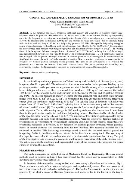
Abstract. In the handling and usage processes, sufficient density and durability <strong>of</strong> biomass (straw, read)<br />
briquettes should be provided. The orientation <strong>of</strong> straw or reed stalks had to promote binding by the pressing<br />
operation. In the previous investigations was stated that the density <strong>of</strong> the arranged reed and hemp stalk particles<br />
exceeds the recommended in standards 1000 kg·m -3 and reaches the value 1185 kg·m -3 for the arranged hemp<br />
stalk particles with the length 150 mm and briquetting pressure 212 MPa. The specific briquetting energy <strong>of</strong><br />
coarse chopped arranged reed and hemp stalk particles ranges from 51.61 kJ·kg -1 to 67.23 kJ·kg -1 . In comparison<br />
the fine chopped reed particle briquetting energy gives the maximum specific energy 40 kJ·kg -1 . The splitting<br />
force <strong>of</strong> the hemp stalk briquettes ranges from 110 N·mm -1 to 122.37 N·mm -1 , splitting force <strong>of</strong> the arranged<br />
reed particles lies between 65 N·mm -1 and 80 N·mm -1 . The specific splitting force is 2 to 5 times higher than for<br />
non arranged stalk briquettes. Arranged structure <strong>of</strong> biomass particles in briquetting die is recommended for<br />
significant increasing durability <strong>of</strong> stalk material briquettes. New briquetting equipment is necessary to be<br />
designed for biomass particle arranging before pressing. The goal <strong>of</strong> the investigation is to evaluate the<br />
geometric and kinematic parameters <strong>of</strong> the stalk biomass cutter. The article presents the modelling and<br />
experimental results <strong>of</strong> the biomass cutter designed for coarse cutting <strong>of</strong> arranged biomass stalks.<br />
Keywords: biomass, cutters, cutting energy.<br />
Introduction<br />
In the handling and usage processes, sufficient density and durability <strong>of</strong> biomass (straw, read)<br />
briquettes should be provided. The orientation <strong>of</strong> straw or reed stalks had to promote binding by the<br />
pressing operation. In the previous investigations was stated that the density <strong>of</strong> the arranged reed and<br />
hemp stalk particles exceeds the recommended in standards 1000 kg·m -3 and reaches the value<br />
1185 kg·m -3 for the arranged hemp stalk particles with the length 150 mm and briquetting pressure<br />
212 MPa. The specific briquetting energy <strong>of</strong> coarse chopped arranged reed and hemp stalk particles<br />
ranges from 51.61 kJ·kg -1 to 67.23 kJ·kg -1 . In comparison the fine chopped reed particle briquetting<br />
energy gives the maximum specific energy 40 kJ·kg -1 . The splitting force <strong>of</strong> the hemp stalk briquettes<br />
ranges from 110 N·mm -1 to 122.37 N·mm -1 , splitting force <strong>of</strong> the arranged reed particles lies between<br />
65 N·mm -1 and 80 N·mm -1 [1]. The specific splitting force is 2 to 5 times higher than for non arranged<br />
stalk briquettes. The specific cutting energy for 100 mm long stalk particles is more than 7 times lover<br />
then for the particle size used in the traditional briquetting process. The theoretically calculated value<br />
<strong>of</strong> the specific cutting energy is below 1 kJ·kg -1 . The structure <strong>of</strong> long stalk briquettes provides higher<br />
durability because long stalks work like reinforcement bars. Arranged structure <strong>of</strong> biomass particles in<br />
briquetting die is recommended for significant increasing durability <strong>of</strong> stalk material briquettes. New<br />
briquetting equipment is necessary to be designed for biomass particle arranging before pressing.<br />
Reeds in several countries are commonly used for ro<strong>of</strong> building. The necessary material for it is<br />
collected in bundles. This harvesting technology could be used also for reed material planed for<br />
briquetting. Stalks in bundles already are oriented in the direction necessary for it. The topicality <strong>of</strong><br />
this paper is connected with the bundle cutter which provides stalk orientation after cutting. The goal<br />
<strong>of</strong> the investigation is to evaluate the geometric and kinematic parameters <strong>of</strong> the stalk biomass cutter.<br />
The article presents the modelling and experimental results <strong>of</strong> the biomass cutter designed for coarse<br />
cutting <strong>of</strong> arranged biomass stalks.<br />
Materials and methods<br />
The study was carried out at the Institute <strong>of</strong> Mechanics, Faculty <strong>of</strong> Engineering. There are several<br />
methods used in biomass cutting. It has been proved that the lowest energy consumption <strong>of</strong> stalk<br />
shredding provides for shear cutting [2].<br />
In the result <strong>of</strong> the research a cutting method with two rotating knife rollers was developed, Fig. 1.<br />
The experimental model <strong>of</strong> the cutter was designed end experimentally tested. The cutter consists <strong>of</strong><br />
two rotors connected with each other with the gears 3. The blades 2 are mounted on the rotor and are<br />
powered by an electric motor 4. Biomass (common reed stalks) is fed to the knives on the tray 5.<br />
251
ENGINEERING FOR RURAL DEVELOPMENT Jelgava, 24.-25.05.2012.<br />
Angular velocity <strong>of</strong> the rotor was measured using the tachogenerator 6. To determine the geometric<br />
and kinematic parameters <strong>of</strong> the cutter a mathematical model was worked out. The main geometric<br />
parameters are given in Figure 2.<br />
In order to achieve high-quality cutting the blades should contact during rotation. Suppose that the<br />
cutting edges, points 1 and 2, Figure 3, are coming close to each other and cut down a reed. To avoid<br />
jamming the mechanism, the blade <strong>of</strong> the knife edge and the plane must have the proper clearance<br />
around moving.<br />
5<br />
4<br />
6<br />
3<br />
2<br />
1<br />
0<br />
l 0<br />
R 1 R 2<br />
φ 1<br />
φ 2<br />
x 2<br />
x 1<br />
b<br />
Fig. 1. Experimental cutter design:<br />
1 – body; 2 – blades; 3 – gears; 4 – electric<br />
drive; 5 – tray; 6 – tachogenerator<br />
Fig. 2. Geometric parameters <strong>of</strong> the cutter:<br />
R 1 and R 2 – radius <strong>of</strong> the rotors, b – knife edge<br />
projection outside the rotor, l 0 – distance between<br />
the rotor center, x 1 , x 2 – knife blade coordinates<br />
In order to design the proper knife shape, the distances between the knife edges and knife-plane<br />
tangent points ∆y 1 and ∆y 2 and knives overlap ∆x, Fig. 3, should be calculated. To create a knife<br />
movement kinematics model, assume the following notation, Fig. 3: points 1 and 2 – knife edge<br />
points, points n 1 and n 2 – points on the knife planes at the overlap ∆x.<br />
x 2<br />
∆x<br />
0<br />
−ϕ<br />
+ϕ<br />
y2<br />
x1<br />
n 2<br />
n 1 1<br />
φ 1 φ 2<br />
y1<br />
∆y2<br />
∆<br />
2<br />
yn1<br />
∆y1<br />
∆<br />
yn2<br />
Fig. 3. Scheme <strong>of</strong> calculations<br />
At first, calculate knife edge coordinates x 1 and x 2 :<br />
Assume that l 0<br />
= 2R + b , Fig. 2.<br />
Overlap <strong>of</strong> the blades:<br />
x = ( R + b) ⋅ cosϕ<br />
, (1)<br />
1 1<br />
x = (2 R + b) − ( R + b) ⋅ cosϕ<br />
. (2)<br />
2 2<br />
( )<br />
∆ x = x − x = ( R + b) ⋅cosϕ<br />
− 2 R + b + ( R + b) ⋅ cosϕ<br />
, (3)<br />
1 2 1 2<br />
252
ENGINEERING FOR RURAL DEVELOPMENT Jelgava, 24.-25.05.2012.<br />
after simplifying:<br />
1 2<br />
( )<br />
∆ x = ( R + b) ⋅ (cosϕ<br />
+ cos ϕ ) − 2R + b . (4)<br />
Knife edge coordinates y 1 and y 2 can be calculated according formulas (5) and (6):<br />
and<br />
y = ( R + b) ⋅ sinϕ<br />
, (5)<br />
1 1<br />
y = ( R + b) ⋅ sinϕ<br />
. (6)<br />
2 2<br />
Coordinates <strong>of</strong> the points n 1 and n 2 were calculated according to equations (7) and (8):<br />
and<br />
yn1 = y1 − ∆x ⋅ tgϕ1<br />
, (7)<br />
yn2 = y2 − ∆x ⋅ tgϕ2<br />
. (8)<br />
The distances between the knife edge and knife-plane tangent points ∆y 1 and ∆y 2 were calculated<br />
according to formulas: ∆ y1 = y1 − y n 2<br />
and ∆ y2 = y2 − y n 1<br />
.<br />
Given the equations (5), (6), (7) and (8), the distances ∆y 1 and ∆y 2 were calculated:<br />
and<br />
∆ y = ( R + b) ⋅ (sinϕ − sin ϕ ) + [( R + b)(cosϕ + cos ϕ ) − (2 R + b)]<br />
⋅ tgϕ<br />
, (9)<br />
1 1 2 1 2 2<br />
∆ y = ( R + b) ⋅ (sinϕ − sin ϕ ) + [( R + b)(cosϕ + cos ϕ ) − (2 R + b)]<br />
⋅ tgϕ<br />
. (10)<br />
2 2 1 1 2 1<br />
The knife mutual movement speed in the direction <strong>of</strong> x-axis was determined by differentiating ∆x<br />
overlap by time. Assume that the rotational speed is constant, and then the angles ϕ 1 and ϕ 2 are<br />
expressed by formulas (11) and (12);<br />
where ϕ 01 , ϕ 02 − initial angles, rad;<br />
ω − angular velocity, s -1 ;<br />
t – time, s.<br />
ϕ1 = ϕ01 + ω ⋅ t , (11)<br />
ϕ2 = ϕ02 + ω ⋅ t , (12)<br />
Inserting equations (11) and (12) in formula (4), and differentiating, we obtain the velocity change<br />
between the knives, equation (13):<br />
x<br />
( ) ⎡sin<br />
( ) sin ( )<br />
v = −ω ⋅ R + b ⋅ ϕ + ω ⋅ t + ϕ + ω ⋅ t ⎤<br />
⎣ 01 02 ⎦ . (13)<br />
The obtained equations 4, 9, 10 and 13 were used to simulate the kinematic parameters <strong>of</strong> the<br />
cutter.<br />
To determine the cutting energy <strong>of</strong> the reed stalks, the experimental tests were carried out. Energy<br />
consumption for reed stalk cutting has been investigated using experimental equipment Fig. 1. To<br />
calculate the cutting energy the electric drive voltage and current consumption were measured. The<br />
measurement data were recorded with a virtual data logger Picoscope and calculated with Excel<br />
s<strong>of</strong>tware. The total cutting power for one cut was represented by the area underneath the entire power<br />
– time curve, Fig. 4. No-loading energy was recorded and subtracted from the total energy.<br />
253
ENGINEERING FOR RURAL DEVELOPMENT Jelgava, 24.-25.05.2012.<br />
Cutting power, W<br />
14<br />
12<br />
10<br />
8<br />
6<br />
4<br />
2<br />
0<br />
400 500 600 700<br />
Time, ms<br />
Fig. 4. Cutting power depending on the cutting time<br />
The calculation <strong>of</strong> the energy for one cut E 1 is done according to equation (14):<br />
⎡ ⎛ P + P ⎞ ⎛ P + P ⎞ ⎛ P + P ⎞ ⎤<br />
1 ⎜ ⎟ ⎜ ⎟ ... ⎜ ⎟ , (14)<br />
⎢<br />
2 2 2<br />
⎥<br />
⎣⎝ ⎠ ⎝ ⎠ ⎝ ⎠ ⎦<br />
2 1 3 2 n n−1<br />
E = ∆ t + ∆ t + + ∆t<br />
where E 1 – energy for one cut, J;<br />
P 1 – first data point, W;<br />
P 2 – second data point, W;<br />
P n – n th data point, W;<br />
∆t – time interval between the data points, ms.<br />
The total energy E was the sum <strong>of</strong> the one cut energy E 1 <strong>of</strong> the sample. The reed samples were<br />
prepared using 3 and 5 reed stalks for one sample. For the experiments air dried reed stalks were used.<br />
The samples were weighed with electronic scales.<br />
The specific cutting energy E s was calculated for every reed stalk by equation (15):<br />
where E s is the specific cutting energy, J·g -1 ;<br />
n st – quantity <strong>of</strong> the stalks;<br />
n cut – number <strong>of</strong> cuttings;<br />
m s – specific mass <strong>of</strong> the stalks, g.<br />
E<br />
s<br />
E<br />
=<br />
n ⋅ n ⋅ m<br />
st cut s<br />
The specific mass <strong>of</strong> the stalk was calculated according to equation (16):<br />
where m s – specific mass <strong>of</strong> the stalks, g;<br />
n st – quantity <strong>of</strong> the stalks.<br />
m<br />
s<br />
m<br />
n<br />
st<br />
, (15)<br />
= , (16)<br />
Calculations were performed according to the experimental model size: R = 42.5 mm and b =<br />
5 mm. The specific cutting energy was calculated for three overlaps <strong>of</strong> the knives: 0.8, 3.0 and 5.2<br />
mm.<br />
Results and discussion<br />
To determine the geometric and kinematical parameters <strong>of</strong> the cutter suppose that the drive rotor<br />
is the left rotor in Fig. 3. Suppose that the rotor rotation is a clockwise direction and the angle is equal<br />
to zero if a knife lies on the right <strong>of</strong> the centre <strong>of</strong> rotation. The change <strong>of</strong> the parameters was modelled<br />
for the rotation angles -25º < ϕ < 25º. Τhe distance between the knife edge and knife-plane tangent<br />
254
ENGINEERING FOR RURAL DEVELOPMENT Jelgava, 24.-25.05.2012.<br />
point ∆y 1 , and the knife overlap was determined for different rotation angles and the angular<br />
differences. It was assumed that at the starting point |ϕ 01 | < |ϕ 02 |. The angular difference was calculated<br />
as |ϕ 02 | − |ϕ 01 |. Cutting <strong>of</strong> the biomass occurs when the knives come close each other. If the rotor<br />
angular difference ∆ϕ is equal to zero, the blades are facing directly to the edges when the overlap <strong>of</strong><br />
the knives is equal to zero (Fig. 5a).<br />
Parameter<br />
6<br />
5<br />
4<br />
3<br />
r<br />
e<br />
te 2<br />
m1<br />
a<br />
ra<br />
P<br />
0<br />
-1<br />
-2<br />
-3<br />
dy1<br />
dx<br />
vx<br />
-25 -20 -15 -10 -5 0 5 10 15 20 25<br />
Angle, deg.<br />
6<br />
5<br />
4<br />
3<br />
r<br />
e<br />
te 2<br />
m1<br />
a<br />
ra<br />
P<br />
0<br />
-1<br />
-2<br />
-3<br />
dy1<br />
dx<br />
vx<br />
-25 -20 -15 -10 -5 0 5 10 15 20 25<br />
Angle, deg.<br />
a) ∆ϕ = 0 b) ∆ϕ = 0.8<br />
Fig. 5. Kinematic and geometrical parameters depending on the rotation angle: dy1 – distance<br />
between the knife edge and knife-plane tangent points ∆y 1 , mm; dx – overlap <strong>of</strong> the blades, mm;<br />
vx – velocity change between the knives, m·s -1<br />
Further rotation <strong>of</strong> the knife blade crosses the other knife plane and cuts into it. The maximum<br />
cut-in depth reaches 0.62 mm (Fig. 6). To avoid jamming <strong>of</strong> the mechanism, a proper form <strong>of</strong> the<br />
knife surface should be designed.<br />
0.3 0,3<br />
0.2 0,2<br />
0.1 0,1<br />
0<br />
-0.1 -0,1<br />
-0.2 -0,2<br />
-0.3 -0,3<br />
-0.4 -0,4<br />
-0.5 -0,5<br />
-0.6 -0,6<br />
-0.7 -0,7<br />
0 0.2 0,2 0.4 0,4 0.6 0,6 0.8 0,8 1<br />
Angular difference, deg<br />
Distance, mm<br />
Fig. 6. Maximum penetration <strong>of</strong> the knife edge 1 in the knife-plane n 2<br />
depending on the angular difference<br />
Such location <strong>of</strong> the blade provides biomass shear cutting. The mutual velocity <strong>of</strong> the blades<br />
exceeds 2 m·s -1 , Fig. 5a. Increasing <strong>of</strong> the angular difference ∆ϕ decreases cut-in depth in the knife<br />
plane. If the angular displacement reaches 0.8 degrees, a blade <strong>of</strong> the knife 1 just touches the other<br />
knife plane when the overlap <strong>of</strong> the knives reaches 3 mm. The mutual movement <strong>of</strong> the blade speed is<br />
1.2 m·s -1 , Fig. 5b. As the knife blade is in contact with the plane direct shear cutting does not occur.<br />
Specific cutting energy was stated for three overlays <strong>of</strong> the knives with different rotation velocity.<br />
Samples were formed with three and five stalks, Fig. 7.<br />
As can be seen from Figure 7, the specific cutting energy <strong>of</strong> the samples with three stalks is less<br />
than for samples from five stalks <strong>of</strong> the knives overlay to 3.0 mm. If the knife overlay is 5.2 mm, the<br />
specific cutting energy decreases.<br />
Parameter<br />
255
ENGINEERING FOR RURAL DEVELOPMENT Jelgava, 24.-25.05.2012.<br />
E, J·g-1<br />
0.07<br />
0.06<br />
0.05<br />
0.04<br />
0.03<br />
0.02<br />
0.01<br />
0<br />
0.043 0.048 0.03<br />
0.057<br />
0.041<br />
0.061<br />
0.033<br />
0.055<br />
0.046<br />
0.039<br />
0.047<br />
1 2 3 4 5 6 7 8 9 10 11 12<br />
Samples<br />
Fig. 7. Specific cutting energy for different cutter parameters<br />
Explanation for Fig. 7<br />
0.041<br />
Table 3<br />
Number <strong>of</strong><br />
samples<br />
Overlay,<br />
mm<br />
Angular<br />
velocity, s -1<br />
Number<br />
<strong>of</strong> stalks<br />
Number <strong>of</strong><br />
samples<br />
Overlay,<br />
mm<br />
Angular<br />
velocity, s -1<br />
Number<br />
<strong>of</strong> stalks<br />
1 1.3 24 3 stalks 7 3 31.4 3 stalks<br />
2 1.3 24 5 stalks 8 3 31.4 5 stalks<br />
3 1.3 31.4 3 stalks 9 5.2 24 3 stalks<br />
4 1.3 31.4 5 stalks 10 5.2 24 5 stalks<br />
5 3 24 3 stalks 11 5.2 31.4 3 stalks<br />
6 3 24 5 stalks 12 5.2 31.4 5 stalks<br />
Conclusions<br />
1. If the rotor angular difference is equal to zero, the blades are facing directly to the edges and<br />
provide biomass shear cutting with the mutual velocity <strong>of</strong> the blades 2 m·s -1 . Maximum <strong>of</strong> the cutin<br />
depth <strong>of</strong> the blade in the knife plane reaches 0.62 mm.<br />
2. Increasing <strong>of</strong> the angular displacement <strong>of</strong> the blades to 0.8 º decreases the cut-in depth <strong>of</strong> the<br />
blade to zero and decreases the mutual velocity <strong>of</strong> cutting to 1.2 m·s -1 .<br />
3. The cutting energy ranges from 0.03 J·g -1 to 0.04 J·g -1 for the samples <strong>of</strong> three stalks and from<br />
0.05 J·g -1 to 0.06 J·g -1 for the samples <strong>of</strong> 5 stalks when the blade overlap does not exceed 3mm.<br />
4. If the blade ceiling is 5.2 mm, the specific cutting energy <strong>of</strong> three stalks is rising to 0.05 J·g -1 , but<br />
for five stalks goes down to 0.04 J·g -1 .<br />
5. The geometric and kinematic model will be used to design the proper blade shape and determine<br />
the most appropriate blade speed.<br />
Acknowledgments<br />
This publication has been prepared within the framework <strong>of</strong> the ERAF Project “Development <strong>of</strong><br />
mechanisation equipment for energy crops conditioning”, contract<br />
No. 2010/0306/2DP/2.1.1.1.0/10/APIA/VIAA/128.<br />
References<br />
1. <strong>Kakitis</strong> A., <strong>Nulle</strong> I., <strong>Ancans</strong> D. Mechanical properties <strong>of</strong> energy crops, 10th International<br />
scientific conference “Engineering for rural development” proceedings, May 26 - 27, 2011<br />
/ <strong>Latvia</strong> <strong>University</strong> <strong>of</strong> Agriculture. Faculty <strong>of</strong> Engineering. Institute <strong>of</strong> Mechanics. - Jelgava,<br />
2011. – pp. 440 – 445.<br />
2. Kronbergs E., Smits M. Cutting properties <strong>of</strong> common reed biomass, 8th International scientific<br />
conference “Engineering for rural development” proceedings, May 28 - 29, 2009 / <strong>Latvia</strong><br />
<strong>University</strong> <strong>of</strong> Agriculture. Faculty <strong>of</strong> Engineering. Institute <strong>of</strong> Mechanics. - Jelgava, 2009. – pp.<br />
207 – 211.<br />
256