043-092a HWBP-8D Instr Sheet - Lutron
043-092a HWBP-8D Instr Sheet - Lutron
043-092a HWBP-8D Instr Sheet - Lutron

You also want an ePaper? Increase the reach of your titles
YUMPU automatically turns print PDFs into web optimized ePapers that Google loves.
Installation <strong>Instr</strong>uctions<br />
Important Note<br />
The HomeWorks InteractiveTM breaker panels are<br />
required to be installed in a way to provide sufficient<br />
access and working space according to the National<br />
Electrical Code (NEC). Depending on the installation<br />
conditions, a typical installation may require 3-4 ft. in<br />
front of the panel and a 30 in. width (to provide enough<br />
space for personnel to perform examination, adjustment,<br />
servicing and maintenance of the equipment). Please<br />
consult your local electrical inspector for all NEC and<br />
local installation requirements (other possible<br />
requirements may include maximum and minimum<br />
breaker height above the floor, proximity to distribution<br />
panel, room size and room entrance specifications).<br />
Installation<br />
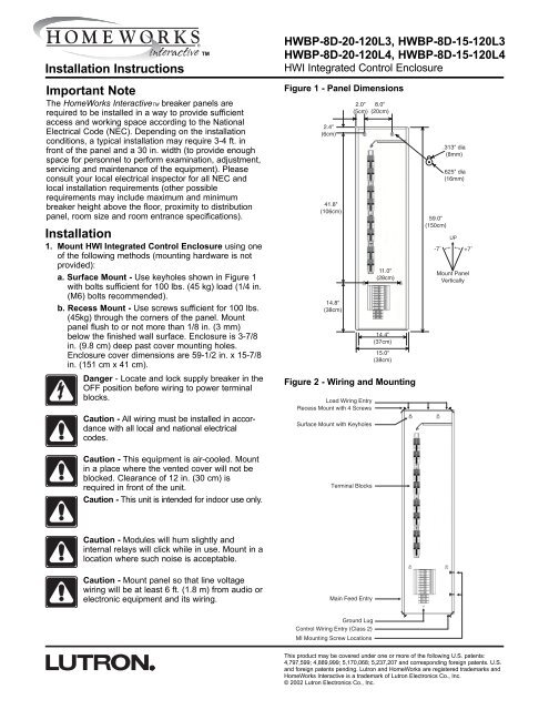
1. Mount HWI Integrated Control Enclosure using one<br />
of the following methods (mounting hardware is not<br />
provided):<br />
a. Surface Mount - Use keyholes shown in Figure 1<br />
with bolts sufficient for 100 lbs. (45 kg) load (1/4 in.<br />
(M6) bolts recommended).<br />
b. Recess Mount - Use screws sufficient for 100 lbs.<br />
(45kg) through the corners of the panel. Mount<br />
panel flush to or not more than 1/8 in. (3 mm)<br />
below the finished wall surface. Enclosure is 3-7/8<br />
in. (9.8 cm) deep past cover mounting holes.<br />
Enclosure cover dimensions are 59-1/2 in. x 15-7/8<br />
in. (151 cm x 41 cm).<br />
Danger - Locate and lock supply breaker in the<br />
OFF position before wiring to power terminal<br />
blocks.<br />
Caution - All wiring must be installed in accordance<br />
with all local and national electrical<br />
codes.<br />
TM<br />
<strong>HWBP</strong>-<strong>8D</strong>-20-120L3, <strong>HWBP</strong>-<strong>8D</strong>-15-120L3<br />
<strong>HWBP</strong>-<strong>8D</strong>-20-120L4, <strong>HWBP</strong>-<strong>8D</strong>-15-120L4<br />
HWI Integrated Control Enclosure<br />
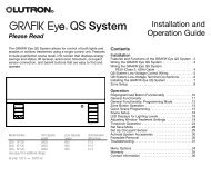
Figure 1 - Panel Dimensions<br />
2.4"<br />
(6cm)<br />
41.8"<br />
(106cm)<br />
14.8"<br />
(38cm)<br />
2.0" 8.0"<br />
(5cm) (20cm)<br />
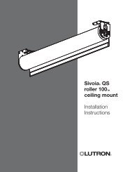
Figure 2 - Wiring and Mounting<br />
Load Wiring Entry<br />
Recess Mount with 4 Screws<br />
Surface Mount with Keyholes<br />
11.0"<br />
(28cm)<br />
14.4"<br />
(37cm)<br />
15.0"<br />
(38cm)<br />
59.0"<br />
(150cm)<br />
-7˚<br />
.313" dia<br />
(8mm)<br />
.625" dia<br />
(16mm)<br />
UP<br />
+7˚<br />
Mount Panel<br />
Vertically<br />
Caution - This equipment is air-cooled. Mount<br />
in a place where the vented cover will not be<br />
blocked. Clearance of 12 in. (30 cm) is<br />
required in front of the unit.<br />
Caution - This unit is intended for indoor use only.<br />
Terminal Blocks<br />
Caution - Modules will hum slightly and<br />
internal relays will click while in use. Mount in a<br />
location where such noise is acceptable.<br />
Caution - Mount panel so that line voltage<br />
wiring will be at least 6 ft. (1.8 m) from audio or<br />
electronic equipment and its wiring.<br />
Main Feed Entry<br />
Ground Lug<br />
Control Wiring Entry (Class 2)<br />
MI Mounting Screw Locations<br />
This product may be covered under one or more of the following U.S. patents:<br />
4,797,599; 4,889,999; 5,170,068; 5,237,207 and corresponding foreign patents. U.S.<br />
and foreign patents pending. <strong>Lutron</strong> and HomeWorks are registered trademarks and<br />
HomeWorks Interactive is a trademark of <strong>Lutron</strong> Electronics Co., Inc.<br />
© 2002 <strong>Lutron</strong> Electronics Co., Inc.
2. Run power wiring (120V/240V 1 Phase 3 Wire,<br />
120V/208V 3 Phase 4 Wire) into the panel.<br />
Locations to run power wiring into the panel are<br />
shown in Figure 2. Wire strip length should be 9/16 in.<br />
(1 cm). The Main Lug will accept wire up to 2/Ø.<br />
Tighten Lug to 50 in-lbs. (5.6 Nm) for #14 to 8 AWG<br />
and 120 in-lbs. (13.5 Nm) for #6 to 2/Ø. The <strong>HWBP</strong>-<br />
<strong>8D</strong>-20-120L3 and <strong>HWBP</strong>-<strong>8D</strong>-15-120L3 should be fed<br />
with an 80A single-phase feed. The <strong>HWBP</strong>-<strong>8D</strong>-20-<br />
120L4 and <strong>HWBP</strong>-<strong>8D</strong>-15-120L4 should be fed with a<br />
60A three-phase feed. All module and control feed<br />
wiring is pre-wired.<br />
3. Install load wiring. Each module controls up to 4<br />
loads. Wiring for the HW-RPM-4U, HW-RPM-4E and<br />
HW-RPM-4FSQ module is shown in Figure 3. (Wiring<br />
for HW-RPM-4M module will differ. Refer to the<br />
installation instructions packaged with the module.)<br />
The HW-RPM-4R module is not compatible with this<br />
panel.<br />
Caution - If a module location will be used with<br />
a HW-RPM-4M module, tie off the load wiring<br />
with a wire connector rather than terminating it<br />
to the terminal blocks. New replacement<br />
terminal blocks will be provided with these<br />
modules.<br />
LABEL EACH WIRE CLEARLY AS YOU WIRE TO THE<br />
TERMINAL BLOCKS.<br />
4. Test all load wiring. Turn on input power to the<br />
module locations. Check all connected lighting to<br />
ensure it is on. If a breaker trips, a wiring error or<br />
excessive load exists and must be resolved. The preinstalled<br />
bypass jumpers will distribute power to each<br />
load and MUST NOT be removed until after all loads<br />
are fully tested and all modules are installed (see<br />
Figure 3).<br />
Caution - Do not remove bypass jumpers at<br />
this time. They will be removed after the<br />
modules are installed.<br />
5. Mount MI mounting screws. If enclosure is recess<br />
(flush) mounted, install MI mounting screws that are<br />
provided. See Figure 2 for locations.<br />
6. Complete panel cover label. Record load names for<br />
each zone on the panel cover label.<br />
7. Install cover. Ensure vents are on the right hand side<br />
of the cover, over the module area. Tighten cover<br />
screws to 20 in-lbs. (2.3 Nm). If a module interface<br />
has not been installed, leave this instruction sheet in<br />
the enclosure.<br />
Technical and Sales Assistance<br />
If you need assistance, call the toll-free <strong>Lutron</strong><br />
Technical Support Center. Please provide exact<br />
model number when calling.<br />
(800) 523-9466 (U.S.A., Canada and the Caribbean)<br />
Other countries call:<br />
Tel: (610) 282-3800<br />
Fax: (610) 282-3090<br />
Visit our Web site at www.lutron.com<br />
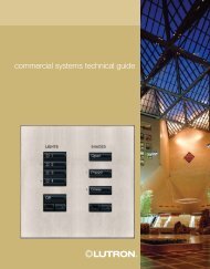
Figure 3 - Module Wiring (HW-RPM-4U, HW-RPM-4E, and HW-<br />
RPM-4FSQ only)<br />
Load<br />
Torque Terminal Blocks from 3.5 - 5 in-lbs (0.4 - 0.57 Nm)<br />
Figure 4 - Dedicated Control Assembly Feed<br />
Input Hot From Control Breaker<br />
(pre-wired)<br />
Neutral From Main Lug<br />
(pre-wired)<br />
H<br />
H<br />
N<br />
N<br />
N<br />
G<br />
Output 1<br />
Output 2<br />
Output 3<br />
Output 4<br />
Input Hot from Module Breaker (pre-wired)<br />
(Module 1 of 8 shown)<br />
Input Neutral from Main Lug (pre-wired)<br />
Load Neutral 1<br />
Load Neutral 2<br />
Load Neutral 3<br />
Load Neutral 4<br />
Black<br />
Feed<br />
Plug<br />
White<br />
MOVs<br />
(Do Not Remove)<br />
Green/Yellow<br />
World Headquarters<br />
<strong>Lutron</strong> Electronics Co., Inc.<br />
7200 Suter Road<br />
Coopersburg, PA 18036-1299, U.S.A.<br />
TOLL FREE: (800) 523-9466 (U.S.A., Canada and the Caribbean)<br />
Tel: (610) 282-3800; International 1 610 282-3800<br />
Fax: (610) 282-3090; International 1 610 282-3090<br />
LIMITED WARRANTY<br />
<strong>Lutron</strong> will, at its option, repair or replace any unit that is defective in materials or manufacture<br />
within two years after purchase. For warranty service, return unit to place of purchase or mail<br />
to <strong>Lutron</strong> at 7200 Suter Rd., Coopersburg, PA 18036-1299, postage pre-paid. Telephone the<br />
<strong>Lutron</strong> Technical Support Center toll free at 800-523-9466. After the two year period, a prorated<br />
warranty applies to this product until eight years after the purchase. For more<br />
information regarding this warranty contact your <strong>Lutron</strong> representative.<br />
THIS WARRANTY IS IN LIEU OF ALL OTHER EXPRESS WARRANTIES, AND THE<br />
IMPLIED WARRANTY OF MERCHANTABILITY IS LIMITED TO TWO YEARS FROM<br />
PURCHASE. THIS WARRANTY DOES NOT COVER THE COST OF INSTALLATION,<br />
REMOVAL OR REINSTALLATION, OR DAMAGE RESULTING FROM MISUSE, ABUSE,<br />
OR IMPROPER OR INCORRECT REPAIR, OR DAMAGE FROM IMPROPER WIRING OR<br />
INSTALLATION. THIS WARRANTY DOES NOT COVER INCIDENTAL OR<br />
CONSEQUENTIAL DAMAGES. LUTRON’S LIABILITY ON ANY CLAIM FOR DAMAGES<br />
ARISING OUT OF OR IN CONNECTION WITH THE MANUFACTURE, SALE,<br />
INSTALLATION, DELIVERY, OR USE OF THE UNIT SHALL NEVER EXCEED THE<br />
PURCHASE PRICE OF THE UNIT.<br />
This warranty gives you specific legal rights, and you may also have other rights which vary<br />
from state to state. Some states do not allow limitations on how long an implied warranty<br />
lasts, so the above limitation may not apply to you. Some states do not allow the exclusion<br />
or limitation of incidental or consequential damages, so the above limitation or exclusion may<br />
not apply to you.<br />
DH<br />
1<br />
DH<br />
2<br />
DH<br />
3<br />
DH<br />
4<br />
H<br />
N<br />
N<br />
N<br />
N<br />
N<br />
Bypass Jumper<br />
(Do not remove<br />
until after the<br />
modules are<br />
installed)<br />
Red<br />
Black<br />
White<br />
<strong>Lutron</strong> Electronics Co., Inc.<br />
7200 Suter Road<br />
Coopersburg, PA 18036-1299<br />
Made and printed in the U.S.A. 3/02 P/N <strong>043</strong>-092 Rev. A