ELC - Alpermann+Velte
ELC - Alpermann+Velte
ELC - Alpermann+Velte

Create successful ePaper yourself
Turn your PDF publications into a flip-book with our unique Google optimized e-Paper software.
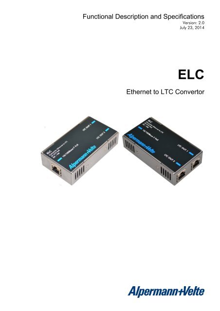
Functional Description and Specifications<br />
Version: 2.0<br />
July 23, 2014<br />
<strong>ELC</strong><br />
Ethernet to LTC Convertor
Functional Description and Specifications <strong>ELC</strong><br />
Page 3<br />
CONTENTS<br />
A1<br />
A2<br />
A3<br />
A4<br />
A5<br />
REVISION HISTORY<br />
COPYRIGHT<br />
CERTIFICATIONS & COMPLIANCES<br />
WARRANTY<br />
UNPACKING/SHIPPING/REPACKAGING INFORMATION<br />
1 DESCRIPTION 8<br />
1.1 INTRODUCTION 8<br />
1.2 CONNECTIONS AND SPECIFICATIONS 9<br />
1.3 POWER SUPPLY 10<br />
1.4 STATUS INDICATION BY LED 11<br />
1.5 MOUNTING 12<br />
2 FIRMWARE UPDATE 13<br />
3 SOFTWARE TOOLS FOR <strong>ELC</strong> 14<br />
3.1 THE UD/SC CONFIGURATION PROGRAM 14<br />
3.2 THE INTEGRATED ETHERNET SERVER 15<br />
3.3 CONFIGURATION 16<br />
3.3.1 General 16<br />
3.3.2 “Profile“: Store and Load a Complete Set-Up 17<br />
3.3.3 “System“: View and Change System Parameters 18<br />
3.3.4 “Source“: Select the Signal Source 19<br />
3.3.5 “Ethernet“: Set-Up of Network Parameters 20<br />
3.3.6 “Real-Time“: NTP Real-Time Parameters 22<br />
3.3.7 “Output“: Set-Up of LTC Outputs 23<br />
4 APPLICATIONS 27<br />
4.1 MTD TIMER SYSTEM AND LTC DISPLAYS 27<br />
4.2 GENERATE LTC - UTC AND LTC - LOCAL TIME 28
Functional Description and Specifications <strong>ELC</strong><br />
Page 4<br />
A1 Revision History<br />
No. Date Subject<br />
0.n Preliminary documents, changes without notice.<br />
1.0 October 16, 2012 First release.<br />
1.1 November 30, 2012 Chapter “Output – Set-Up of LTC Outputs” revised.<br />
1.2 April 02, 2014 Chapter “System: View and Change System Parameters”: added note if password is lost.<br />
2.0 July 23, 2014 Completely revised. Set-up can now be done via integrated Ethernet server.<br />
Due to constant product development the features of <strong>ELC</strong> are subject to change. The current<br />
functional description always refers to the current firmware and the current configuration tool.<br />
You can download the latest version of the standard firmware from<br />
http://www.alpermann-velte.com/serv_e/software_e/software_e.html.<br />
Please be sure to use the latest configuration program after having done an update. You can<br />
download the latest version from the address above.
Functional Description and Specifications <strong>ELC</strong><br />
Page 5<br />
A2<br />
Copyright<br />
Copyright © <strong>Alpermann+Velte</strong> Electronic Engineering GmbH 2002. All rights reserved. No<br />
part of this publication may be reproduced, translated into another language, stored in a<br />
retrieval system, or transmitted, in any form or by any means, electronic, mechanical, photocopying,<br />
recording, or otherwise without the prior written consent of <strong>Alpermann+Velte</strong><br />
Electronic Engineering GmbH.<br />
Printed in Germany.<br />
Technical changes are reserved.<br />
All brand and product names mentioned herein are used for identification purposes only, and<br />
are trademarks or registered trademarks of their respective holders.<br />
Information in this publication replaces all previously published information. <strong>Alpermann+Velte</strong><br />
Electronic Engineering GmbH assumes no responsibility for errors or omissions. Neither is any<br />
liability assumed for damages resulting from the use of the information contained herein.<br />
For further information please contact your local dealer or:<br />
<strong>Alpermann+Velte</strong><br />
Electronic Engineering GmbH<br />
Otto-Hahn-Str. 42<br />
D-42369 Wuppertal<br />
Phone: ++49 - (0)202 – 244 111 0<br />
Fax: ++49 - (0)202 – 244 111 5<br />
E-Mail: info@alpermann-velte.com<br />
Internet: http://www.alpermann-velte.com<br />
A3<br />
Certifications & Compliances<br />
CE-Declaration <strong>ELC</strong>:<br />
We,<br />
<strong>Alpermann+Velte</strong><br />
Electronic Engineering GmbH<br />
Otto-Hahn-Str. 42<br />
D-42103 Wuppertal<br />
herewith declare under our sole responsibility that the<br />
<strong>ELC</strong><br />
meets the intent of the following directives, standards and specifications:<br />
2004/108/EC<br />
EMC Directive<br />
applying the following standards:<br />
EN 55022:2006<br />
Emission<br />
EN 55024:1998 + A1:2001 + A2:2003 Immunity
Functional Description and Specifications <strong>ELC</strong><br />
Page 6<br />
A3<br />
Warranty<br />
<strong>Alpermann+Velte</strong> warrants that their products will be free from defects in materials and<br />
workmanship for a period of two years from the date of shipment. If this product proves<br />
defective during the warranty period, <strong>Alpermann+Velte</strong>, at its option, will repair or replace the<br />
defective product without charge, provided this product are returned to <strong>Alpermann+Velte</strong><br />
freight prepaid.<br />
In order to obtain service under this warranty, Customer must notify <strong>Alpermann+Velte</strong> of the<br />
defect before expiration of the warranty period and make suitable arrangements for the<br />
performance of service. Customer shall be responsible for packaging and shipping the<br />
defective product to <strong>Alpermann+Velte</strong>, please notice the Shipping Information given below.<br />
This warranty shall not apply to any defect, failure or damage caused by abuse, misuse,<br />
improper use, negligence, accident, modification, alteration, or improper or inadequate<br />
maintenance and care.<br />
This warranty is given by <strong>Alpermann+Velte</strong> with respect to this product in lieu of any other<br />
warranties, express or implied. <strong>Alpermann+Velte</strong> and its vendors disclaim any implied<br />
warranties of merchantability or fitness for a particular purpose. <strong>Alpermann+Velte</strong>’s responsibility<br />
to repair or replace defective products is the sole and exclusive remedy provided to the<br />
customer for breach of this warranty. <strong>Alpermann+Velte</strong> and its vendors will not be liable for<br />
any indirect, special, incidental, or consequential damages irrespective of whether<br />
<strong>Alpermann+Velte</strong> or the vendor has advance notice of the possibility of such damages.
Functional Description and Specifications <strong>ELC</strong><br />
Page 7<br />
A4<br />
Unpacking/Shipping/Repackaging Information<br />
This product has been carefully inspected, tested and calibrated before shipment to ensure<br />
years of stable and trouble-free service.<br />
The shipping carton and pads provide protection for the product during transit. Retain the<br />
shipping cartons in case subsequent shipment becomes necessary.<br />
Carefully unpack the product from its transit material and carefully check the product for signs<br />
of damage. In the event that the product has been damaged during transit, contact the carrier<br />
and your <strong>Alpermann+Velte</strong> dealer.<br />
Please confirm that all items listed on the packing list have been received. Check the items<br />
against your original order to ensure that you have received the correct parts. If any item is<br />
missing, please contact your <strong>Alpermann+Velte</strong> dealer.<br />
Ensure that all packaging material is removed from the product and its associated<br />
components before installing the unit.<br />
Products returned to <strong>Alpermann+Velte</strong> for servicing or repair should have a tag attached<br />
showing:<br />
<br />
<br />
Name and complete address of the owner and the name of the person that can be<br />
contacted.<br />
Unit’s serial number and a description of the service required or failure detected.<br />
Products returned should be shipped prepaid in the original packaging material if possible. If<br />
the original packaging is not available or is unfit for use, supply an adequate packaging<br />
which should meet the following criteria:<br />
<br />
<br />
<br />
<br />
<br />
Packaging must be able to withstand the product weight.<br />
Product must be held rigid within the packaging.<br />
Allow at least one inch of space between the product and the container.<br />
The corners of the product must be protected.<br />
Seal the carton with shipping tape or an industrial stapler.<br />
If the product is still within the warranty period, the product will be returned by prepaid
Functional Description and Specifications <strong>ELC</strong><br />
Page 8<br />
1 Description<br />
1.1 Introduction<br />
<strong>ELC</strong> serves as an LTC generator with two output stages. The data content within the LTC time<br />
code is either fed from an NTP server or an MTDoE master device. Both LTC output signals are<br />
phase locked to UTC time which is available as well in NTP mode as in MTDoE mode. Time<br />
addresses as well as user data (binary groups) of the LTC can be independently configured<br />
and generated.<br />
These are the key features of <strong>ELC</strong>:<br />
<br />
<br />
<br />
<br />
<br />
<br />
<br />
<br />
<br />
PoE power supply.<br />
Connectors: 1 x RJ45 for Ethernet/PoE, 2 x RJ45 for LTC outputs.<br />
Set-up and firmware update possible via the “UD SC Config“ program.<br />
Set-up and status display possible via the integrated Ethernet server.<br />
All settings will be stored at a non-volatile memory, so the latest set-up will not get lost<br />
if <strong>ELC</strong> was powered off.<br />
Frame rate of LTC outputs selectable: 24/25/30/29.97 frames per second.<br />
LTC signal level adjustable for each output separately.<br />
Source = NTP:<br />
• One “Primary“ and one “Secondary“ NTP Server can be addressed.<br />
• Various date formats can be transported in the binary groups (user data) of the<br />
LTC.<br />
• Based on UTC received from the NTP Server, <strong>ELC</strong> can output a time & date LTC of<br />
any time zone, with or without Daylight Saving Time switching.<br />
Source = MTD:<br />
• Selectable MTDoE group.<br />
• Time addresses of LTC can be a local real-time or a time of any MTD counter.<br />
• A date can be transported in the binary groups (user data) of the LTC.
Functional Description and Specifications <strong>ELC</strong><br />
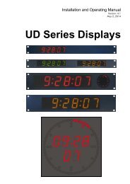
1.2 Connections and Specifications<br />
Page 9<br />
STAT<br />
ACT<br />
Green LED STAT<br />
indicates status.<br />
Yellow LED ACT<br />
indicates Ethernet<br />
activity.<br />
10/100Base-T PoE<br />
RJ45 jack<br />
1: Tx+ / V PoE +<br />
2: Tx– / V PoE +<br />
3: Rx+ / V PoE –<br />
4: V PoE +<br />
5: V PoE +<br />
6: Rx– / V PoE –<br />
7: V PoE –<br />
8: V PoE –<br />
LTC OUT 2 LTC OUT 1<br />
2 x RJ45 jack<br />
Pin assignment of both outputs and<br />
adaption to XLR3 connector:<br />
Signal RJ45 XLR3<br />
GND 4 1<br />
LTC OUT + 3 2<br />
LTC OUT – 6 3<br />
Operating voltage<br />
Power consumption<br />
Weight<br />
Dimensions<br />
Environmental<br />
characteristics,<br />
operating<br />
Environmental<br />
characteristics, nonoperating<br />
Ethernet connector<br />
Ethernet<br />
LTC output<br />
According to PoE specification (48 VDC nominal)<br />
≤ 2 W<br />
0.2 kg<br />
W x H x D: 100 x 26 x 56 mm; 3.94 x 1.02 x 2.20 inches<br />
Temperature: 5 °C to 40 °C<br />
Relative humidity:<br />
30 % to 85 %, non-condensing<br />
Temperature: -10 °C to +60 °C<br />
Relative humidity:<br />
RJ45 jack 10/100 BASE-T<br />
10/100Base-T<br />
5 % to 95 %, non-condensing<br />
Balanced LTC (Linear Time Code) outputs.<br />
Format:<br />
according to SMPTE 12M-1-2008<br />
Output impedance: < 50 <br />
Connecting and signal levels (adjustable):<br />
balanced use<br />
to XLR3F<br />
GND<br />
LTC OUT -<br />
LTC OUT +<br />
2 1<br />
3<br />
unbalanced<br />
to Cinch/RCA/BNC<br />
LTC OUT +<br />
GND<br />
LTC OUT -<br />
Minimum: –16.1 dBu/0.3 V pp –22.2 dBu/0.17 V pp<br />
Maximum: +8.5 dBu/5.8 V pp +2.5 dBu/2.9 V pp
Functional Description and Specifications <strong>ELC</strong><br />
Page 10<br />
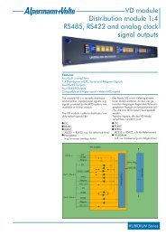
1.3 Power Supply<br />
<strong>ELC</strong> receives power via “Power over Ethernet“ (PoE). Power over Ethernet or PoE technology<br />
describes a system to pass electrical power, along with data, on Ethernet cabling. Just connect<br />
<strong>ELC</strong> to a PoE port of a switch.<br />
PoE Switch<br />
<strong>ELC</strong><br />
PoE<br />
10/100Base-T PoE<br />
If no PoE port is available, use the PI external PoE injector. You can order this part with order<br />
number 14085015.<br />
Non-PoE Switch<br />
<strong>ELC</strong><br />
10/100Base-T PoE<br />
Power-over-Ethernet Injector<br />
External Power Supply:<br />
Option PI<br />
~ AC Power
Functional Description and Specifications <strong>ELC</strong><br />
Page 11<br />
1.4 Status Indication by LED<br />
The green LED STAT indicates the operating status of the unit.<br />
Event Status LED<br />
Power just turned<br />
on<br />
First NTP query<br />
Synchronization<br />
Synchronized<br />
No IP address assigned for the unit, DHCP is still<br />
running.<br />
No LTC output.<br />
First NTP query after power has turned on or after<br />
changing the set-up regarding NTP server.<br />
No LTC output.<br />
NTP query has been successful, but synchronization<br />
still is running.<br />
No LTC output.<br />
Normal operation.<br />
As long as the LTC output is switch on, LTC will be<br />
generated – even if synchronization will be lost.<br />
Flickering<br />
Off,<br />
lights up shortly<br />
once per second<br />
On,<br />
turns off shortly<br />
once per second<br />
On<br />
Faults<br />
DHCP successful,<br />
but no<br />
communication<br />
NTP server not<br />
available<br />
NTP server lost<br />
MTD master lost<br />
“Source = MTD”: No MTD master found yet.<br />
“Source = NTP”: Invalid NTP server address (e.g.<br />
0.0.0.0).<br />
No LTC output.<br />
No return from NTP server at all.<br />
No LTC output.<br />
“Source = NTP”: Timeout, communication between<br />
<strong>ELC</strong> and NTP server is disrupted.<br />
As long as the LTC output is switch on, LTC will be<br />
generated.<br />
“Source = MTD”: Timeout, communication between<br />
<strong>ELC</strong> and MTD master is disrupted.<br />
As long as the LTC output is switch on, LTC will be<br />
generated.<br />
Flashing:<br />
1 s on – 1 s off<br />
Off,<br />
turns off shortly<br />
twice per second<br />
On,<br />
turns off shortly<br />
twice per second<br />
On,<br />
turns off shortly<br />
twice per second
Functional Description and Specifications <strong>ELC</strong><br />
Page 12<br />
1.5 Mounting<br />
There are two threaded holes (M3) at the bottom of the unit.<br />
Maximum screw-in depth: 15 mm/0.59 inches.<br />
100 mm<br />
50 mm<br />
56 mm<br />
<strong>Alpermann+Velte</strong><br />
Drawing not to scale!<br />
PREVENT OVERHEATING<br />
To prevent product overheating, position the unit only where sufficient air<br />
circulation can be maintained. Good air circulation is essential to prevent internal<br />
heat build-up, do not block any ventilation openings. Do not expose the unit to<br />
direct sun light or any other strong lights. Keep the unit away from heat sources.<br />
PROVIDE PROPER ENVIRONMENT<br />
Dust, humidity, shocks and strong electromagnetic fields must be avoided. Do not<br />
expose this unit to dripping or splashing water. Ensure that no objects filled with<br />
liquid are placed on the unit.
2 Firmware Update<br />
Functional Description and Specifications <strong>ELC</strong><br />
Page 13<br />
Firmware updates require a computer with the UD SC Config program and an Ethernet connection.<br />
Computer and <strong>ELC</strong> have to be connected to the same network. When using a<br />
firewall, either disable it or ensure that the computer can connect to the unit on UDP port<br />
8051 for both incoming and outgoing traffic.<br />
Please have the new firmware (.tcf file) stored on your computer. The latest firmware is<br />
available at:<br />
http://www.alpermann-velte.com/serv_e/software_e/software_e.html.<br />
Execute UD SC Config on your computer. The program gives a list of all MTD devices found<br />
in the network. <strong>ELC</strong> should be on this list. Access via Ethernet can be protected by a password<br />
(please refer to chapter “System”: View and Change System Parameters).<br />
Select the <strong>ELC</strong> line, open the File menu, choose Flash Update..., and open the .tcf file.<br />
During the flash update the operation of the device stops!
Functional Description and Specifications <strong>ELC</strong><br />
Page 14<br />
3 Software Tools for <strong>ELC</strong><br />
3.1 The UD/SC Configuration Program<br />
Via the UD SC Config program you can locate and setup <strong>ELC</strong> units in your network. It runs<br />
on a computer (32/64 bit Windows operating systems 2000/XP/2003/Vista/2008/7). You can<br />
download the latest version of the program from:<br />
http://www.alpermann-velte.com/serv_e/software_e/software_e.html.<br />
<strong>ELC</strong> set-up is done via Ethernet; the computer must be connected to the same network. Access<br />
via Ethernet can be protected by a password (please refer to chapter “System”: View and<br />
Change System Parameters).<br />
Firmware update is performed by this program as well. Please refer to chapter “Firmware<br />
Update”.<br />
After program start a list is given of all MTD devices and their IP addresses found in your local<br />
network:<br />
Select the <strong>ELC</strong> line and click button “Configure”, or double click on the line. Additional tabs<br />
will be shown. On these tabs you can check or change the set-up as described in chapter<br />
“Configuration”.
Functional Description and Specifications <strong>ELC</strong><br />
3.2 The Integrated Ethernet Server<br />
Page 15<br />
Start an Internet Browser and type in the IP address of <strong>ELC</strong>. If you do not know the IP address,<br />
start the UD SC Config program (refer to chapter “The UD/SC Configuration Program”).<br />
The menu at the left border offers three links: System and NTP Status – where you can have<br />
status information; and Configuration – which enables to set-up the <strong>ELC</strong> module (please<br />
refer to chapter “Configuration“).<br />
System indicates the installed<br />
firmware and the current network<br />
parameters.<br />
NTP Status indicates the most<br />
relevant information regarding<br />
the NTP Client functionality.
Functional Description and Specifications <strong>ELC</strong><br />
Page 16<br />
3.3 Configuration<br />
3.3.1 General<br />
You can do a set-up of <strong>ELC</strong> via the UD SC Config PC program or via the integrated Ethernet<br />
server.<br />
Set-up via UD SC Config:<br />
After program start the <strong>ELC</strong> module should appear in the list. Select the <strong>ELC</strong> line and<br />
click button , or double click on the line – this opens the configuration.<br />
Additional tabs will be shown which will be described in the following chapters.<br />
Set-up via integrated Ethernet server:<br />
Start an Internet Browser and type in the IP address of the <strong>ELC</strong> module. Click<br />
Configuration in the menu at the left border – this opens the configuration. A new<br />
menu appears which shows a list of all configuration pages which are currently<br />
available. With a click on one of these entries of the menu a configuration page will be<br />
opened where you can see and change parameters. Each configuration page will be<br />
described in the following chapters.
Functional Description and Specifications <strong>ELC</strong><br />
Page 17<br />
3.3.2 “Profile“: Store and Load a Complete Set-Up<br />
Configuration options (example shows a screen shot of the Ethernet server):<br />
This feature enables to easily change the complete set-up of the unit during normal operation.<br />
During installation, the current set-up can be stored as a “profile”. You can enter a name in<br />
the “name” entry before storing. Now choose a different set-up and store this as a different<br />
profile. Fife profiles are available.<br />
Five different set-ups can be stored into the<br />
non-volatile memory of the unit.<br />
Click Store:<br />
Any set-up stored as a profile can replace<br />
the current set-up.<br />
Click Load:<br />
Profile: Select 1 – 5.<br />
Info Operator: You may enter a text.<br />
Comment: You may enter a text.<br />
Click OK to store the current set-up.<br />
Profile: Select “Factory Settings“ or 1 – 5.<br />
“Factory Settings“ installs the<br />
default set-up.<br />
Click OK to replace the current set-up by<br />
the selected profile. If no valid set-up has<br />
been stored, an error message is given.
Functional Description and Specifications <strong>ELC</strong><br />
Page 18<br />
3.3.3 “System“: View and Change System Parameters<br />
Configuration options (example shows a screen shot of the Ethernet server):<br />
Unit<br />
Name<br />
Reboot<br />
Give the device a significant name. This name appears wherever <strong>ELC</strong> devices can<br />
be found.<br />
Enter a text (10 characters) in the Name field. Complete with Enter or Tab key.<br />
Warm boot of the unit.<br />
Security<br />
It is provided to protect the unit against non permission or unintentional access via Ethernet.<br />
With a click on the Change button the following entry opens:<br />
Enter the password twice and press the OK button.<br />
Clear an existing password by checking No Password.<br />
Password forgotten? → Please read chapter “Passwords” of “The MTD System” manual.<br />
Info<br />
Indicates some device status, e.g. the version of the installed firmware.
Functional Description and Specifications <strong>ELC</strong><br />
Page 19<br />
3.3.4 “Source“: Select the Signal Source<br />
Configuration options (example shows a screen shot of the Ethernet server):<br />
MTD<br />
NTP<br />
<strong>ELC</strong> is able to convert data of an MTDoE system to LTC. These data include six<br />
independent programmable timers, real-time, date, and a time of a time code.<br />
Each timer can show a stop timer, a remaining time, a time difference, a time<br />
of a time zone etc.<br />
For a detailed description of the MTDoE system please read the manual The<br />
MTD System – Installation and Operation Manual.<br />
<strong>ELC</strong> transfers a time & date into LTC. The reference time, received from an NTP<br />
server, can get a programmable offset. It is possible to enable a Daylight<br />
Saving Time handling.
Functional Description and Specifications <strong>ELC</strong><br />
Page 20<br />
3.3.5 “Ethernet“: Set-Up of Network Parameters<br />
Configuration options (example shows a screen shot of the UD SC Config PC program):<br />
“Source = MTD“<br />
“Source = NTP“<br />
Current Settings<br />
This box indicates the current network parameters of the device.<br />
Only available with the UD SC Config PC program:<br />
A click on Change... enables to change parameters:<br />
Use DHCP<br />
If checked, the device will automatically request its IP parameters (IP address,<br />
subnet mask, and gateway) from a DHCP server. In this case the “IP Address”,<br />
“Subnet Mask”, and “Gateway” boxes have no relevance.<br />
Please let the device restart (power off – on) if you select this mode.
Functional Description and Specifications <strong>ELC</strong><br />
Page 21<br />
MTD - if “Source = MTD“ has been selected<br />
Automatic MTD Master IP Address If checked, the device will automatically find the<br />
MTDoE central unit responsible for the group number below.<br />
In a redundant system (two MTDoE central units), an<br />
automatic changeover can take place in case one central<br />
unit fails.<br />
MTD Master IP Address If “Automatic Host IP Address” is not checked, the IP address<br />
of the MTDoE central unit has to be entered manually.<br />
Group<br />
Indicates the MTDoE group number. Likewise, you can<br />
change this number here.<br />
Click Reload Page at the bottom of the tab if the „Current Settings“ box does not show the<br />
new parameters.<br />
NTP Client - if “Source = NTP“ has been selected<br />
Enter the IP addresses which the NTP client of the device uses to request time & date<br />
information of an NTP server.<br />
Primary Server IP Address Address of the primary (1st) NTP server.<br />
Secondary Server IP Address Address of a secondary (back-up) NTP Server.<br />
Click Reload Page at the bottom of the tab if the „Current Settings“ box does not show a<br />
changed address.
Functional Description and Specifications <strong>ELC</strong><br />
Page 22<br />
3.3.6 “Real-Time“: NTP Real-Time Parameters<br />
“Source = NTP“ only.<br />
Configuration options (example shows a screen shot of the Ethernet server):<br />
<strong>ELC</strong> receives time & date from an NTP server according to the set-up at the “Ethernet” tab.<br />
Time and date refers to UTC (Universal Time Coordinated = world time reference without a<br />
Daylight Saving Time [DST]). Having the UTC as a time base, any local time zone can be<br />
calculated and displayed.<br />
Enable Real-Time Enables or disables the time zone handling.<br />
If checked, offsets will be calculated and a DST switching can be done automatically.<br />
If not checked, the generated time corresponds to the reference time without offset.<br />
Local Time Zone 1 / 2 Local time zone will be defined with respect to UTC. <strong>ELC</strong> has two<br />
independent programmable LTC outputs; therefore two time zones can be programmed<br />
independently.<br />
Offset from UTC Sign and hours/minutes offset for standard time (winter time).<br />
If the time zone has a DST period, the following parameters should be programmed:<br />
Automatically set Daylight Saving Time Check, if reference input has a DST period.<br />
DST Bias Enter the DST correction value. Most of the cases the correction value will be<br />
(+) one hour.<br />
DST Start Using these inputs (e.g. last Sunday of March at 2 o’clock) the device<br />
calculates the start of DST for the current year.<br />
DST End Using these inputs (e.g. last Sunday of October at 3 o’clock) the device<br />
calculates the end of DST for the current year.
Functional Description and Specifications <strong>ELC</strong><br />
Page 23<br />
3.3.7 “Output“: Set-Up of LTC Outputs<br />
Configuration options (example shows a screen shot of the Ethernet server):<br />
Frame Rate Select the frame rate of both LTC outputs:<br />
Auto<br />
24<br />
25<br />
30<br />
30 df / 29.97<br />
Please note: An LTC counting for a 29.97 Hz system (drop-frame mode) has<br />
severe difficulties in a real-time application, because an odd number of frames<br />
per second will be generated.<br />
“Auto“: If “Source = NTP“: frame rate equal to 25.<br />
If “Source = MTD“: frame rate set from MTDoE master device.
Functional Description and Specifications <strong>ELC</strong><br />
Page 24<br />
LTC 1 / LTC 2<br />
Data content and level of both LTC outputs can be set individually. The mode of<br />
synchronization is fixed for both outputs, so that each time code word starts at exactly the<br />
same time.<br />
Time<br />
This entry determines what will be the data content of the time addresses of the<br />
time code. Any time code reader will display these data in a “time” mode.<br />
“Source = MTD“<br />
Real-Time Local real-time.<br />
Timer A (B, C, D, E, F) Time of counter A (B, C, D, E, F).<br />
Main 1 (2, 3) Time of MTD “main time“ 1 (2, 3).<br />
Time Code Time of a time code of the MTDoE system.<br />
“Source = NTP“<br />
UTC<br />
Time Zone 1<br />
Time Zone 2<br />
Reference time without any offset or DST correction.<br />
Time of time zone 1 – refer to “Real-Time“ tab.<br />
Time of time zone 2 – refer to “Real-Time“ tab..<br />
User<br />
This entry determines what will be the data content of the user data (binary<br />
groups) of the time code. Any time code reader will display these data in a “user”<br />
mode.<br />
The user data consists of eight four-bit groups which will be denoted as BG1 to<br />
BG8, and they are paired in the following way:<br />
BG8/7 = “Hours“,<br />
BG6/5 = “Minutes“,<br />
BG4/3 = “Seconds“,<br />
BG2/1 = “Frames“.<br />
Date formats: A “U” in a date format receives that value of the binary group<br />
which has been entered at the “Set User” entry for this position. DD denotes the<br />
day, MM the month, YY the year – all BCD coded.<br />
Set<br />
Fixed values as programmed at the “Set User“ entry.<br />
--- Date --- Various date formats.<br />
“Source = MTD“: Date refers to local time.<br />
“Source = NTP“: Date refers to the time zone selected at “Time“.<br />
Survey of various BCD coded formats:<br />
BG8/7 BG6/5 BG4/3 BG2/1<br />
UU.DD.MM.YY U U DD M M YY<br />
DD.MM.YY.YY DD M M YY YY<br />
YY.MM.DD.UU YY M M DD U U<br />
UU.YY.MM.DD U U YY M M DD<br />
UY.YM.MD.DU U Y Y M M D D U<br />
DD.MM.YY.UU DD M M YY U U<br />
MM.DD.YY.UU M M DD YY U U<br />
UU.MM.DD.YY U U M M DD YY
Functional Description and Specifications <strong>ELC</strong><br />
Page 25<br />
BBC Date coded according to the “EBU Technical Information I29-<br />
1995” (so-called BBC format). The date is BCD coded and<br />
assigned to the binary groups as follows:<br />
BG1 Reserved All bits = 0<br />
BG2 Units of the day 4 bits, LSB = bit 12<br />
BG3 Units of the month 4 bits, LSB = bit 20<br />
BG4 Tens of the day 2 bits, LSB = bit 28<br />
Tens of the month 1 bit = bit 30, bit 31 = 0<br />
BG5 Reserved All bits = 0<br />
BG6 Units of the year 4 bits, LSB = bit 44<br />
BG7 Reserved All bits = 0<br />
BG8 Tens of the year 4 bits, LSB = bit 60<br />
309M: YYMMDD Date and time zone information according to the SMPTE<br />
309M-1999 “YYMMDD” format.<br />
309M: MJD Date and time zone information according to the SMPTE 309M-<br />
1999 “MJD” format.<br />
--- MTD --- “Source = MTD“: Counter values decoded out of the MTD data:<br />
Timer A (B, C, D, E, F) Time of counter A (B, C, D, E, F).<br />
Real-Time<br />
Local real-time.<br />
Main 1 (2, 3) Time of MTD “main time“ 1 (2, 3).<br />
Time Code<br />
Time of a time code of the MTDoE system.<br />
Set User<br />
Gain<br />
Manual entry of user data. Enter 8 characters (0 – 9, A – F). Complete with Enter<br />
or Tab key.<br />
Select the output level from the drop-down list. You can mute an output by<br />
selecting “off”.<br />
The values in this list refer to a use of balanced signals for output and input, i.e.<br />
V PP (= peak-to-peak value) will be the difference between LTC OUT + and LTC<br />
OUT –. V PP will be half of the indicated value if unbalanced signals are used, i.e.<br />
the peak-to-peak value of the single LTC OUT + or LTC OUT – signal.<br />
Correspondence between balanced use and unbalanced use:<br />
Use of balanced signals<br />
Maximum: +8.5 dBu / 5.8 V PP<br />
Use of unbalanced signals<br />
+2.5 dBu / 2.9 V PP<br />
+6.2 dBu / 4.5 V PP 0.2 dBu / 2.2 V PP<br />
+2.0 dBu / 2.8 V PP –4.0 dBu / 1.4 V PP<br />
–6.5 dBu / 1.0 V PP –12.5 dBu / 0.5 V PP<br />
Minimum: –16.1 dBu / 0.3 V PP<br />
–22.1 dBu / 0.17 V PP
Functional Description and Specifications <strong>ELC</strong><br />
Page 26<br />
Digits<br />
Still -<br />
PC Bit<br />
“6 Digits” or “8 Digits” can be selected. This set-up is relevant only if one of the<br />
MTD timers “Timer A – F“ or “Main 1 – 3“ has been selected and this timer is<br />
counting down. If a display or a similar device reads this LTC and displays the<br />
time without frames (e.g. HH:MM:SS), the “6 Digits” mode should be selected. If<br />
this device displays the time with frames, the “8 Digits” mode should be selected.<br />
The correct choice ensures that the down-counting time at the display reaches 0<br />
synchronous with the original MTD time.<br />
For example: MTD timer counting down from 1s to 0s<br />
MTD Timer <strong>ELC</strong>-LTC “6 Digits“ Display HH:MM:SS Display MM:SS:FF<br />
00:00:01 00:00:01:00 00:00:01 00:01:00<br />
00:00:00 00:00:00:24 00:00:00 00:00:24<br />
MTD Timer <strong>ELC</strong>-LTC “8 Digits“ Display HH:MM:SS Display MM:SS:FF<br />
00:00:01 00:00:00:01 00:00:00 00:00:01<br />
00:00:00 00:00:00:00 00:00:00 00:00:00<br />
Usually an LTC reader compensates the decoding delay of one frame by adding<br />
one frame to the current value being indicated. Some readers can switch off this<br />
compensation automatically receiving a "still" LTC; this ensures a frame accurate<br />
value while the LTC time stands still. If the LTC is connected to a display or a<br />
similar device which utilizes this compensations mechanism, do not click "Still –",<br />
otherwise "Still –" should be clicked.<br />
Example: Standing LTC time = 01:02:03:04<br />
<strong>ELC</strong>-LTC with "Still –" Device with compensation Device without compensation<br />
01:02:03:03 01:02:03:03 01:02:03:04<br />
<strong>ELC</strong>-LTC without "Still –" Device with compensation Device without compensation<br />
01:02:03:04 01:02:03:04 01:02:03:05<br />
If checked: The polarity of the synchronization word of the LTC output will be<br />
stabilised. The polarity correction bit is put in a state, so that every 80-bit word<br />
contains an even number of logical zeros. The polarity correction bit is bit no. 27<br />
in the 525/60 system, no. 59 in the 625/50 system. Checking this checkbox is<br />
helpful if you do some LTC measurements with an oscilloscope.<br />
During normal operation mode you can let it unchecked.<br />
Down Reverse The LTC word can be generated with a “forward” or “reverse” code.<br />
Independent from this, the time addresses of the LTC can count upwards,<br />
downwards, or can stop counting. This especially will become true if <strong>ELC</strong><br />
generates the time of a stop timer (e.g. timer A of the MTD system).<br />
If Down Reverse is not checked, the LTC signal always has the “forward” code.<br />
Some LTC readers may run into problems if the code will not match the direction<br />
of counting. Check Down Reverse to overcome this problem.<br />
During normal operation mode you can let it checked.
4 Applications<br />
Functional Description and Specifications <strong>ELC</strong><br />
Page 27<br />
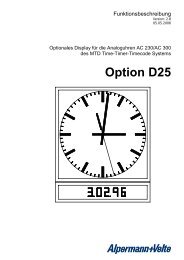
4.1 MTD Timer System and LTC Displays<br />
<strong>ELC</strong> offers an easy and cost effective opportunity to display UP or DOWN counters of the<br />
<strong>Alpermann+Velte</strong> MTD system at Non-<strong>Alpermann+Velte</strong> displays. These displays must be able<br />
to read SMPTE/EBU time code (LTC).<br />
LTC OUT 2<br />
<strong>ELC</strong><br />
LTC OUT 1<br />
<strong>Alpermann+Velte</strong><br />
TIMER A<br />
DOWN<br />
7 8 9<br />
4 5 6<br />
1 2 3<br />
+ 0<br />
_<br />
OFFSET DIFF<br />
DOWN TIME TIME<br />
STOP<br />
START RESET<br />
Local<br />
Network<br />
IN<br />
2 1<br />
3<br />
LTC Display: Timer A<br />
TCUE / SPT<br />
LTC Display: Timer B<br />
2 1<br />
3<br />
IN<br />
<strong>ELC</strong> set-up: “Source“: Select MTD.<br />
“Ethernet“:<br />
“Output“:<br />
Check Automatic MTD Master IP Address and select your MTD<br />
group (normally = 1).<br />
LTC 1 – Time: e.g. “Timer A“; LTC 1 – User: e.g. “Set“.<br />
LTC 2 – Time: e.g. “Timer B“; LTC 1 – User: e.g. “Set“.<br />
Digits = “6 Digits”, if the connected device (display) does not<br />
indicated frames.<br />
Digits = “8 Digits”, if the connected device (display) indicates<br />
frames.<br />
Note:<br />
If it is required to show more than two counters, additional <strong>ELC</strong> units can be<br />
integrated.
Functional Description and Specifications <strong>ELC</strong><br />
Page 28<br />
4.2 Generate LTC - UTC and LTC - Local Time<br />
<strong>ELC</strong> offers an easy and cost effective opportunity to provide one LTC line with UTC reference<br />
time and a second LTC line with local time.<br />
LTC - UTC<br />
LTC - local time<br />
NTP<br />
Server<br />
LTC OUT 2 LTC OUT 1 1 2<br />
3<br />
<strong>ELC</strong><br />
1 2<br />
3<br />
1 2<br />
3<br />
IN<br />
1 2<br />
3<br />
2 1<br />
3<br />
1 2<br />
3<br />
1 2<br />
3<br />
1 2<br />
3<br />
IN<br />
1 2<br />
3<br />
OUT OUT OUT OUT OUT OUT OUT OUT<br />
AUDIO<br />
DISTRIBUTION<br />
AUDIO<br />
DISTRIBUTION<br />
2 1<br />
3<br />
<strong>ELC</strong> set-up: “Source“: Select NTP.<br />
“Ethernet“:<br />
Enter the IP address of your NTP server at the NTP Client<br />
entry.<br />
“Real-Time“: Check Enable Real-Time and program Local Time Zone 1.<br />
“Output“:<br />
LTC 1 – Time = UTC; LTC 1 – User = any date format.<br />
LTC 2 – Time = Time Zone 1; LTC 2 – User = any date format.<br />
Notes:<br />
This application basically does not provide LTC outputs which are phase<br />
locked to a video sync signal. The LTC outputs are locked to video, if<br />
the video sync generator (SPG) is frequency and phase locked to a realtime<br />
source (e.g. locked by PPS and 10 MHz signals of a GPS receiver),<br />
and the NTP server for <strong>ELC</strong> uses the same real-time reference as the video<br />
sync generator (SPG),<br />
and the video system provides an even number of pictures per second (PAL<br />
625/50, but not NTSC 525/59.94).<br />
Please remember that an LTC counting for a 29.97 Hz system (drop-frame<br />
mode) has severe difficulties in a real-time application.