TSC2046: Low Voltage I/O Touch Screen Controller (Rev. B)
TSC2046: Low Voltage I/O Touch Screen Controller (Rev. B)
TSC2046: Low Voltage I/O Touch Screen Controller (Rev. B)

You also want an ePaper? Increase the reach of your titles
YUMPU automatically turns print PDFs into web optimized ePapers that Google loves.
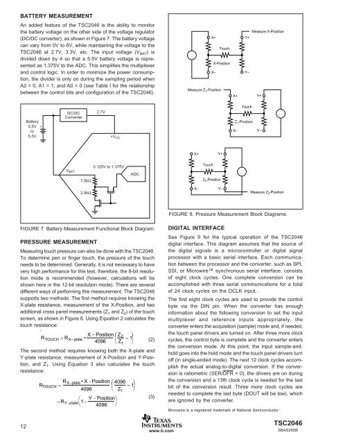
BATTERY MEASUREMENT<br />
An added feature of the <strong>TSC2046</strong> is the ability to monitor<br />
the battery voltage on the other side of the voltage regulator<br />
(DC/DC converter), as shown in Figure 7. The battery voltage<br />
can vary from 0V to 6V, while maintaining the voltage to the<br />
<strong>TSC2046</strong> at 2.7V, 3.3V, etc. The input voltage (V BAT ) is<br />
divided down by 4 so that a 5.5V battery voltage is represented<br />
as 1.375V to the ADC. This simplifies the multiplexer<br />
and control logic. In order to minimize the power consumption,<br />
the divider is only on during the sampling period when<br />
A2 = 0, A1 = 1, and A0 = 0 (see Table I for the relationship<br />
between the control bits and configuration of the <strong>TSC2046</strong>).<br />
Measure X-Position<br />
X+ Y+<br />
<strong>Touch</strong><br />
X-Position<br />
X– Y–<br />
Measure Z 1 -Position<br />
X+ Y+<br />
Battery<br />
0.5V +<br />
to<br />
5.5V<br />
DC/DC<br />
Converter<br />
2.7V<br />
+V CC<br />
<strong>Touch</strong><br />
Z 1 -Position<br />
X–<br />
Y–<br />
X+ Y+<br />
V BAT<br />
7.5kΩ<br />
0.125V to 1.375V<br />
ADC<br />
<strong>Touch</strong><br />
Z 2 -Position<br />
2.5kΩ<br />
X–<br />
Y–<br />
Measure Z 2 -Position<br />
FIGURE 8. Pressure Measurement Block Diagrams.<br />
FIGURE 7. Battery Measurement Functional Block Diagram.<br />
PRESSURE MEASUREMENT<br />
Measuring touch pressure can also be done with the <strong>TSC2046</strong>.<br />
To determine pen or finger touch, the pressure of the touch<br />
needs to be determined. Generally, it is not necessary to have<br />
very high performance for this test, therefore, the 8-bit resolution<br />
mode is recommended (however, calculations will be<br />
shown here in the 12-bit resolution mode). There are several<br />
different ways of performing this measurement. The <strong>TSC2046</strong><br />
supports two methods. The first method requires knowing the<br />
X-plate resistance, measurement of the X-Position, and two<br />
additional cross panel measurements (Z 1 and Z 2 ) of the touch<br />
screen, as shown in Figure 8. Using Equation 2 calculates the<br />
touch resistance:<br />
R TOUCH = R X– plate • X – Position ⎛<br />
⎜<br />
Z 2 ⎞<br />
–1⎟<br />
4096 ⎝ Z 1 ⎠<br />
(2)<br />
The second method requires knowing both the X-plate and<br />
Y-plate resistance, measurement of X-Position and Y-Position,<br />
and Z 1 . Using Equation 3 also calculates the touch<br />
resistance:<br />
R TOUCH = R X−plate •X−Position<br />
4096<br />
⎛<br />
–R Y−plate 1− Y − Position ⎞<br />
⎝ 4096 ⎠<br />
⎛ 4096 ⎞<br />
⎜ –1⎟<br />
⎝ Z 1 ⎠<br />
(3)<br />
DIGITAL INTERFACE<br />
See Figure 9 for the typical operation of the <strong>TSC2046</strong><br />
digital interface. This diagram assumes that the source of<br />
the digital signals is a microcontroller or digital signal<br />
processor with a basic serial interface. Each communication<br />
between the processor and the converter, such as SPI,<br />
SSI, or Microwire synchronous serial interface, consists<br />
of eight clock cycles. One complete conversion can be<br />
accomplished with three serial communications for a total<br />
of 24 clock cycles on the DCLK input.<br />
The first eight clock cycles are used to provide the control<br />
byte via the DIN pin. When the converter has enough<br />
information about the following conversion to set the input<br />
multiplexer and reference inputs appropriately, the<br />
converter enters the acquisition (sample) mode and, if needed,<br />
the touch panel drivers are turned on. After three more clock<br />
cycles, the control byte is complete and the converter enters<br />
the conversion mode. At this point, the input sample-andhold<br />
goes into the hold mode and the touch panel drivers turn<br />
off (in single-ended mode). The next 12 clock cycles accomplish<br />
the actual analog-to-digital conversion. If the conversion<br />
is ratiometric (SER/DFR = 0), the drivers are on during<br />
the conversion and a 13th clock cycle is needed for the last<br />
bit of the conversion result. Three more clock cycles are<br />
needed to complete the last byte (DOUT will be low), which<br />
are ignored by the converter.<br />
Microwire is a registered trademark of National Semiconductor.<br />
12<br />
www.ti.com<br />
<strong>TSC2046</strong><br />
SBAS265B