TSC2046: Low Voltage I/O Touch Screen Controller (Rev. B)
TSC2046: Low Voltage I/O Touch Screen Controller (Rev. B)
TSC2046: Low Voltage I/O Touch Screen Controller (Rev. B)

You also want an ePaper? Increase the reach of your titles
YUMPU automatically turns print PDFs into web optimized ePapers that Google loves.
®<br />
<strong>TSC2046</strong><br />
®<br />
®<br />
<strong>TSC2046</strong><br />
<strong>TSC2046</strong><br />
<strong>TSC2046</strong><br />
<strong>Low</strong> <strong>Voltage</strong> I/O<br />
TOUCH SCREEN CONTROLLER<br />
SBAS265B – OCTOBER 2002 – REVISED AUGUST 2003<br />
FEATURES<br />
• SAME PINOUT AS ADS7846<br />
• 2.2V TO 5.25V OPERATION<br />
• 1.5V TO 5.25V DIGITAL I/O<br />
• INTERNAL 2.5V REFERENCE<br />
• DIRECT BATTERY MEASUREMENT (0V to 6V)<br />
• ON-CHIP TEMPERATURE MEASUREMENT<br />
• TOUCH-PRESSURE MEASUREMENT<br />
• QSPI TM AND SPI TM 3-WIRE INTERFACE<br />
• AUTO POWER-DOWN<br />
• AVAILABLE IN TSSOP-16, QFN-16, AND<br />
VFBGA-48 PACKAGES<br />
APPLICATIONS<br />
• PERSONAL DIGITAL ASSISTANTS<br />
• PORTABLE INSTRUMENTS<br />
• POINT-OF-SALE TERMINALS<br />
• PAGERS<br />
• TOUCH SCREEN MONITORS<br />
• CELLULAR PHONES<br />
US Patent No. 6246394<br />
QSPI and SPI are registered trademarks of Motorola.<br />
Pen<br />
Detect<br />
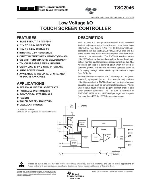
DESCRIPTION<br />
The <strong>TSC2046</strong> is a next-generation version to the ADS7846<br />
4-wire touch screen controller which supports a low-voltage<br />
I/O interface from 1.5V to 5.25V. The <strong>TSC2046</strong> is 100% pincompatible<br />
with the existing ADS7846, and will drop into the<br />
same socket. This allows for easy upgrade of current applications<br />
to the new version. The <strong>TSC2046</strong> also has an onchip<br />
2.5V reference that can be used for the auxiliary input,<br />
battery monitor, and temperature measurement modes. The<br />
reference can also be powered down when not used to<br />
conserve power. The internal reference operates down to<br />
2.7V supply voltage, while monitoring the battery voltage<br />
from 0V to 6V.<br />
The low-power consumption of < 0.75mW typ at 2.7V (reference<br />
off), high-speed (up to 125kHz sample rate), and onchip<br />
drivers make the <strong>TSC2046</strong> an ideal choice for batteryoperated<br />
systems such as personal digital assistants (PDAs)<br />
with resistive touch screens, pagers, cellular phones, and<br />
other portable equipment. The <strong>TSC2046</strong> is available in<br />
TSSOP-16, QFN-16, and VFBGA-48 packages and is specified<br />
over the –40°C to +85°C temperature range.<br />
PENIRQ<br />
X+<br />
X–<br />
Temperature<br />
Sensor<br />
IOVDD<br />
Y+<br />
<strong>TSC2046</strong><br />
DOUT<br />
Y–<br />
BUSY<br />
Comparator<br />
6-Channel<br />
Serial CS<br />
MUX<br />
CDAC<br />
Data<br />
In/Out<br />
V BAT<br />
Battery<br />
DCLK<br />
Monitor<br />
DIN<br />
AUX<br />
SAR<br />
Internal 2.5V<br />
Reference<br />
Please be aware that an important notice concerning availability, standard warranty, and use in critical applications of<br />
Texas Instruments semiconductor products and disclaimers thereto appears at the end of this data sheet.<br />
PRODUCTION DATA information is current as of publication date.<br />
Products conform to specifications per the terms of Texas Instruments<br />
standard warranty. Production processing does not necessarily include<br />
testing of all parameters.<br />
www.ti.com<br />
Copyright © 2002-2003, Texas Instruments Incorporated
ABSOLUTE MAXIMUM RATINGS (1)<br />
+V CC and IOVDD to GND ..................................................... –0.3V to +6V<br />
Analog Inputs to GND ............................................ –0.3V to +V CC + 0.3V<br />
Digital Inputs to GND .......................................... –0.3V to IOVDD + 0.3V<br />
Power Dissipation .......................................................................... 250mW<br />
Maximum Junction Temperature ................................................... +150°C<br />
Operating Temperature Range ....................................... –40°C to +85°C<br />
Storage Temperature Range ......................................... –65°C to +150°C<br />
Lead Temperature (soldering, 10s) ............................................... +300°C<br />
NOTE: (1) Stresses above these ratings can cause permanent damage.<br />
Exposure to absolute maximum conditions for extended periods may degrade<br />
device reliability.<br />
ELECTROSTATIC<br />
DISCHARGE SENSITIVITY<br />
This integrated circuit can be damaged by ESD. Texas<br />
Instruments recommends that all integrated circuits be handled<br />
with appropriate precautions. Failure to observe proper handling<br />
and installation procedures can cause damage.<br />
ESD damage can range from subtle performance degradation<br />
to complete device failure. Precision integrated circuits<br />
may be more susceptible to damage because very small<br />
parametric changes could cause the device not to meet its<br />
published specifications.<br />
PACKAGE/ORDERING INFORMATION<br />
NOMINAL<br />
PENIRQ MAXIMUM<br />
PULLUP INTEGRAL SPECIFIED<br />
RESISTOR LINEARITY PACKAGE TEMPERATURE PACKAGE ORDERING TRANSPORT<br />
PRODUCT VALUES ERROR (LSB) PACKAGE-LEAD DESIGNATOR (1) RANGE MARKING NUMBER MEDIA, QUANTITY<br />
<strong>TSC2046</strong> 50kΩ ±2 VFBGA-48 GQC –40°C to +85°C AZ2046 <strong>TSC2046</strong>IGQCR Tape and Reel, 2500<br />
<strong>TSC2046</strong>-90 90kΩ " " " " AZ2046A <strong>TSC2046</strong>IGQCR-90 "<br />
<strong>TSC2046</strong> 50kΩ ±2 TSSOP-16 PW –40°C to +85°C <strong>TSC2046</strong>I <strong>TSC2046</strong>IPW Rails, 94<br />
" " " " " " " <strong>TSC2046</strong>IPWR Tape and Reel, 2500<br />
<strong>TSC2046</strong> " ±2 QFN-16 RGV –40°C to +85°C <strong>TSC2046</strong> <strong>TSC2046</strong>IRGVT Tape and Reel, 250<br />
" " " " " " " <strong>TSC2046</strong>IRGVR Tape and Reel, 2500<br />
NOTE: (1) For the most current specifications and package information, refer to our web site at www.ti.com.<br />
2<br />
www.ti.com<br />
<strong>TSC2046</strong><br />
SBAS265B
ELECTRICAL CHARACTERISTICS<br />
At T A = –40°C to +85°C, +V CC = +2.7V, V REF = 2.5V internal voltage, f SAMPLE = 125kHz, f CLK = 16 • f SAMPLE = 2MHz, 12-bit mode, digital inputs = GND or IOVDD,<br />
and +V CC must be • IOVDD, unless otherwise noted.<br />
<strong>TSC2046</strong><br />
PARAMETER CONDITIONS MIN TYP MAX UNITS<br />
ANALOG INPUT<br />
Full-Scale Input Span Positive Input-Negative Input 0 V REF V<br />
Absolute Input Range Positive Input –0.2 +V CC + 0.2 V<br />
Negative Input –0.2 +0.2 V<br />
Capacitance 25 pF<br />
Leakage Current 0.1 µA<br />
SYSTEM PERFORMANCE<br />
Resolution 12 Bits<br />
No Missing Codes 11 Bits<br />
Integral Linearity Error ±2 LSB (1)<br />
Offset Error ±6 LSB<br />
Gain Error External V REF ±4 LSB<br />
Noise Including Internal V REF 70 µVrms<br />
Power-Supply Rejection 70 dB<br />
SAMPLING DYNAMICS<br />
Conversion Time 12 CLK Cycles<br />
Acquisition Time 3 CLK Cycles<br />
Throughput Rate 125 kHz<br />
Multiplexer Settling Time 500 ns<br />
Aperture Delay 30 ns<br />
Aperture Jitter 100 ps<br />
Channel-to-Channel Isolation V IN = 2.5Vp-p at 50kHz 100 dB<br />
SWITCH DRIVERS<br />
On-Resistance<br />
Y+, X+ 5 Ω<br />
Y–, X– 6 Ω<br />
Drive Current (2) Duration 100ms 50 mA<br />
REFERENCE OUTPUT<br />
Internal Reference <strong>Voltage</strong> 2.45 2.50 2.55 V<br />
Internal Reference Drift 15 ppm/°C<br />
Quiescent Current 500 µA<br />
REFERENCE INPUT<br />
Range 1.0 +V CC V<br />
Input Impedance SER/DFR = 0, PD1 = 0, 1 GΩ<br />
Internal Reference Off<br />
Internal Reference On 250 Ω<br />
BATTERY MONITOR<br />
Input <strong>Voltage</strong> Range 0.5 6.0 V<br />
Input Impedance<br />
Sampling Battery 10 kΩ<br />
Battery Monitor Off 1 GΩ<br />
Accuracy V BAT = 0.5V to 5.5V, External V REF = 2.5V –2 +2 %<br />
V BAT = 0.5V to 5.5V, Internal Reference –3 +3 %<br />
TEMPERATURE MEASUREMENT<br />
Temperature Range –40°C +85 °C<br />
Resolution Differential Method (3) 1.6 °C<br />
TEMP0 (4) 0.3 °C<br />
Accuracy Differential Method (3) ±2 °C<br />
TEMP0 (4) ±3 °C<br />
DIGITAL INPUT/OUTPUT<br />
Logic Family<br />
CMOS<br />
V IH | I IH | ≤ +5µA IOVDD • 0.7 IOVDD + 0.3 V<br />
V IL | I IL | ≤ +5µA –0.3 0.3 • IOVDD V<br />
V OH I OH = –250µA IOVDD • 0.8 V<br />
V OL I OL = 250µA 0.4 V<br />
Data Format<br />
Straight Binary<br />
POWER-SUPPLY REQUIREMENTS<br />
+V (5) CC Specified Performance 2.7 3.6 V<br />
Operating Range 2.2 5.25 V<br />
IOVDD (6) 1.5 +V CC V<br />
Quiescent Current (7) Internal Reference Off 280 650 µA<br />
Internal Reference On 780 µA<br />
f SAMPLE = 12.5kHz 220 µA<br />
Power-Down Mode with 3 µA<br />
CS = DCLK = DIN = IOVDD<br />
Power Dissipation +V CC = +2.7V 1.8 mW<br />
TEMPERATURE RANGE<br />
Specified Performance –40 +85 °C<br />
NOTES: (1) LSB means least significant bit. With V REF = +2.5V, one LSB is 610µV. (2) Assured by design, but not tested. Exceeding 50mA source current may result<br />
in device degradation. (3) Difference between TEMP0 and TEMP1 measurement, no calibration necessary. (4) Temperature drift is –2.1mV/°C. (5) <strong>TSC2046</strong> operates<br />
down to 2.2V. (6) IOVDD must be - +V CC . (7) Combined supply current from +V CC and IOVDD. Typical values obtained from conversions on AUX input with<br />
PD0 = 0.<br />
<strong>TSC2046</strong> 3<br />
SBAS265B<br />
www.ti.com
PIN CONFIGURATION<br />
Top View<br />
TSSOP<br />
Top View<br />
VFBGA<br />
DCLK<br />
CS DIN BUSY DOUT<br />
+V CC<br />
1<br />
16<br />
DCLK<br />
X+<br />
2<br />
15<br />
CS<br />
1 2 3 4 5 6 7<br />
Y+<br />
3<br />
14<br />
DIN<br />
A<br />
NC<br />
NC<br />
X–<br />
Y–<br />
4<br />
5<br />
<strong>TSC2046</strong><br />
13<br />
12<br />
BUSY<br />
DOUT<br />
+V CC<br />
B<br />
C<br />
NC<br />
NC<br />
NC<br />
NC<br />
NC<br />
NC<br />
NC<br />
NC<br />
NC<br />
PENIRQ<br />
GND<br />
6<br />
11<br />
PENIRQ<br />
+V CC<br />
IOVDD<br />
V BAT<br />
7<br />
10<br />
IOVDD<br />
X+<br />
D<br />
NC<br />
NC<br />
NC<br />
NC<br />
NC<br />
V REF<br />
AUX<br />
8<br />
9<br />
V REF<br />
Y+<br />
E<br />
NC<br />
NC<br />
NC<br />
NC<br />
NC<br />
AUX<br />
F<br />
NC<br />
NC<br />
NC<br />
NC<br />
NC<br />
NC<br />
NC<br />
G<br />
NC<br />
NC<br />
X– Y– GND GND V BAT<br />
Top View<br />
TSSOP<br />
16<br />
15<br />
14<br />
13<br />
DOUT<br />
PENIRQ<br />
IOVDD<br />
V REF<br />
BUSY<br />
1<br />
12<br />
AUX<br />
DIN<br />
CS<br />
2<br />
3<br />
<strong>TSC2046</strong><br />
11<br />
10<br />
V BAT<br />
GND<br />
DCLK<br />
4<br />
9<br />
Y–<br />
+V CC<br />
X+<br />
Y+<br />
X–<br />
5<br />
6<br />
7<br />
8<br />
PIN DESCRIPTION<br />
TSSOP PIN # VFBGA PIN # QFN PIN # NAME DESCRIPTION<br />
1 B1 and C1 5 +V CC Power Supply<br />
2 D1 6 X+ X+ Position Input<br />
3 E1 7 Y+ Y+ Position Input<br />
4 G2 8 X– X– Position Input<br />
5 G3 9 Y– Y– Position Input<br />
6 G4 and G5 10 GND Ground<br />
7 G6 11 V BAT Battery Monitor Input<br />
8 E7 12 AUX Auxiliary Input to ADC<br />
9 D7 13 V REF <strong>Voltage</strong> Reference Input/Output<br />
10 C7 14 IOVDD Digital I/O Power Supply<br />
11 B7 15 PENIRQ Pen Interrupt<br />
12 A6 16 DOUT Serial Data Output. Data is shifted on the falling edge of DCLK. This output is high<br />
impedance when CS is high.<br />
13 A5 1 BUSY Busy Output. This output is high impedance when CS is high.<br />
14 A4 2 DIN Serial Data Input. If CS is low, data is latched on rising edge of DCLK.<br />
15 A3 3 CS Chip Select Input. Controls conversion timing and enables the serial input/output register.<br />
CS high = power-down mode (ADC only).<br />
16 A2 4 DCLK External Clock Input. This clock runs the SAR conversion process and synchronizes serial data<br />
I/O.<br />
4<br />
www.ti.com<br />
<strong>TSC2046</strong><br />
SBAS265B
TYPICAL CHARACTERISTICS<br />
At T A = +25°C, +V CC = +2.7V, IOVDD = +1.8V, V REF = External +2.5V, 12-bit mode, PD0 = 0, f SAMPLE = 125kHz, and f CLK = 16 • f SAMPLE = 2MHz, unless otherwise noted.<br />
400<br />
+V CC SUPPLY CURRENT vs TEMPERATURE<br />
30<br />
IOVDD SUPPLY CURRENT vs TEMPERATURE<br />
+V CC Supply Current (µA)<br />
350<br />
300<br />
250<br />
200<br />
150<br />
IOVDD Supply Current (µA)<br />
25<br />
20<br />
15<br />
10<br />
100<br />
–40 –20 0 20 40 60 80 100<br />
5<br />
–40 –20 0 20 40 60 80 100<br />
Temperature (°C)<br />
Temperature (°C)<br />
140<br />
POWER-DOWN SUPPLY CURRENT vs TEMPERATURE<br />
450<br />
+V CC SUPPLY CURRENT vs +V CC<br />
Supply Current (nA)<br />
120<br />
100<br />
80<br />
60<br />
+V CC Supply Current (µA)<br />
400<br />
350<br />
300<br />
250<br />
200<br />
150<br />
f SAMPLE = 12.5kHz<br />
f SAMPLE = 125kHz<br />
40<br />
–40 –20 0 20 40 60 80 100<br />
Temperature (°C)<br />
100<br />
2.0 2.5 3.0 3.5 4.0 4.5 5.0<br />
+V CC (V)<br />
60<br />
IOVDD SUPPLY CURRENT vs IOVDD<br />
+V CC<br />
≥ IOVDD<br />
1M<br />
MAXIMUM SAMPLE RATE vs +V CC<br />
IOVDD Supply Current (µA)<br />
50<br />
40<br />
30<br />
20<br />
10<br />
f SAMPLE<br />
= 125kHz<br />
f SAMPLE = 12.5kHz<br />
Sample Rate (Hz)<br />
100k<br />
10k<br />
0<br />
1.0 1.5 2.0 2.5 3.0 3.5 4.0 4.5 5.0<br />
IOVDD (V)<br />
1k<br />
2.0 2.5 3.0 3.5 4.0 4.5 5.0<br />
+V CC (V)<br />
<strong>TSC2046</strong> 5<br />
SBAS265B<br />
www.ti.com
TYPICAL CHARACTERISTICS (Cont.)<br />
At T A = +25°C, +V CC = +2.7V, IOVDD = +1.8V, V REF = External +2.5V, 12-bit mode, PD0 = 0, f SAMPLE = 125kHz, and f CLK = 16 • f SAMPLE = 2MHz, unless otherwise noted.<br />
0.15<br />
CHANGE IN GAIN vs TEMPERATURE<br />
0.6<br />
CHANGE IN OFFSET vs TEMPERATURE<br />
0.10<br />
0.4<br />
Delta from +25°C (LSB)<br />
0.05<br />
0<br />
–0.05<br />
–0.10<br />
Delta from +25°C (LSB)<br />
0.2<br />
0<br />
–0.2<br />
–0.4<br />
–0.15<br />
–0.6<br />
–40 –20 0 20 40 60 80 100<br />
–40 –20 0 20 40 60 80 100<br />
Temperature (°C)<br />
Temperature (°C)<br />
14<br />
REFERENCE CURRENT vs SAMPLE RATE<br />
18<br />
REFERENCE CURRENT vs TEMPERATURE<br />
12<br />
16<br />
Reference Current (µA)<br />
10<br />
8<br />
6<br />
4<br />
2<br />
Reference Current (µA)<br />
14<br />
12<br />
10<br />
8<br />
0<br />
0 25 50 75 100 125<br />
Sample Rate (kHz)<br />
6<br />
–40 –20 0 20 40 60 80 100<br />
Temperature (°C)<br />
8<br />
SWITCH ON-RESISTANCE vs +V CC<br />
(X+, Y+: +V CC<br />
to Pin; X–, Y–: Pin to GND)<br />
8<br />
SWITCH ON-RESISTANCE vs TEMPERATURE<br />
(X+, Y+: +V CC<br />
to Pin; X–, Y–: Pin to GND)<br />
Y–<br />
7<br />
Y–<br />
7<br />
6<br />
R ON (Ω)<br />
6<br />
5<br />
X–<br />
R ON (Ω)<br />
5<br />
4<br />
X–<br />
X+, Y+<br />
4<br />
X+, Y+<br />
3<br />
2<br />
3<br />
2.0 2.5 3.0 3.5 4.0 4.5 5.0<br />
+V CC<br />
(V)<br />
1<br />
–40 –20 0 20 40 60 80 100<br />
Temperature (°C)<br />
6<br />
www.ti.com<br />
<strong>TSC2046</strong><br />
SBAS265B
TYPICAL CHARACTERISTICS (Cont.)<br />
At T A = +25°C, +V CC = +2.7V, IOVDD = +1.8V, V REF = External +2.5V, 12-bit mode, PD0 = 0, f SAMPLE = 125kHz, and f CLK = 16 • f SAMPLE = 2MHz, unless otherwise noted.<br />
Max Absolute Delta Error from<br />
R IN = 0 (LSB)<br />
2.0<br />
1.8<br />
1.6<br />
1.4<br />
1.2<br />
1.0<br />
0.8<br />
0.6<br />
0.4<br />
0.2<br />
MAXIMUM SAMPLING RATE vs R IN<br />
INL: R IN = 500Ω<br />
INL: R IN = 2kΩ<br />
DNL: R IN = 500Ω<br />
DNL: R IN = 2kΩ<br />
Internal V REF (V)<br />
2.5080<br />
2.5075<br />
2.5070<br />
2.5065<br />
2.5060<br />
3.5055<br />
2.5050<br />
2.5045<br />
2.5040<br />
2.5035<br />
INTERNAL V REF vs TEMPERATURE<br />
0<br />
20 40 60 80 100 120 140 160 180 200<br />
Sampling Rate (kHz)<br />
2.5030<br />
–40<br />
–35<br />
–30<br />
–25<br />
–20<br />
–15<br />
–10<br />
–5<br />
0<br />
5<br />
10<br />
15<br />
20<br />
25<br />
30<br />
35<br />
40<br />
45<br />
50<br />
55<br />
60<br />
65<br />
70<br />
75<br />
80<br />
85<br />
Temperature (°C)<br />
2.510<br />
INTERNAL V REF vs +V CC<br />
100<br />
INTERNAL V REF vs TURN-ON TIME<br />
Internal V REF (V)<br />
2.505<br />
2.500<br />
2.495<br />
2.490<br />
Internal V REF (%)<br />
80<br />
60<br />
40<br />
No Cap<br />
(42µs)<br />
12-Bit Settling<br />
1µF Cap<br />
(1240µs)<br />
12-Bit Settling<br />
2.485<br />
20<br />
2.480<br />
2.5 3.0 3.5 4.0 4.5 5.0<br />
+V CC (V)<br />
0<br />
0 200 400 600 800 1000 1200 1400<br />
Turn-On Time (µs)<br />
850<br />
TEMP DIODE VOLTAGE vs TEMPERATURE<br />
604<br />
TEMP0 DIODE VOLTAGE vs +V CC<br />
TEMP Diode <strong>Voltage</strong> (mV)<br />
800<br />
750<br />
700<br />
650<br />
600<br />
550<br />
500<br />
90.1mV<br />
TEMP0<br />
TEMP1<br />
135.1mV<br />
TEMP0 Diode <strong>Voltage</strong> (mV)<br />
602<br />
600<br />
598<br />
596<br />
450<br />
–40<br />
–35<br />
–30<br />
–25<br />
–20<br />
–15<br />
–10<br />
–5<br />
0<br />
5<br />
10<br />
15<br />
20<br />
25<br />
30<br />
35<br />
40<br />
45<br />
50<br />
55<br />
60<br />
65<br />
70<br />
75<br />
80<br />
85<br />
Temperature (°C)<br />
594<br />
2.7 3.0 3.3<br />
+V CC (V)<br />
<strong>TSC2046</strong> 7<br />
SBAS265B<br />
www.ti.com
TYPICAL CHARACTERISTICS (Cont.)<br />
At T A = +25°C, +V CC = +2.7V, IOVDD = +1.8V, V REF = External +2.5V, 12-bit mode, PD0 = 0, f SAMPLE = 125kHz, and f CLK = 16 • f SAMPLE = 2MHz, unless otherwise noted.<br />
720<br />
TEMP1 DIODE VOLTAGE vs +V CC<br />
TEMP1 Diode <strong>Voltage</strong> (mV)<br />
718<br />
716<br />
714<br />
712<br />
710<br />
2.7 3.0 3.3<br />
+V CC (V)<br />
THEORY OF OPERATION<br />
The <strong>TSC2046</strong> is a classic successive approximation register<br />
(SAR) analog-to-digital converter (ADC). The architecture is<br />
based on capacitive redistribution, which inherently includes<br />
a sample-and-hold function. The converter is fabricated on a<br />
0.6µm CMOS process.<br />
The basic operation of the <strong>TSC2046</strong> is shown in Figure 1.<br />
The device features an internal 2.5V reference and uses an<br />
external clock. Operation is maintained from a single supply<br />
of 2.7V to 5.25V. The internal reference can be overdriven<br />
with an external, low-impedance source between 1V and<br />
+V CC . The value of the reference voltage directly sets the<br />
input range of the converter.<br />
The analog input (X-, Y-, and Z-Position coordinates, auxiliary<br />
input, battery voltage, and chip temperature) to the converter is<br />
provided via a multiplexer. A unique configuration of low onresistance<br />
touch panel driver switches allows an unselected<br />
ADC input channel to provide power and the accompanying pin<br />
to provide ground for an external device, such as a touch<br />
screen. By maintaining a differential input to the converter and<br />
a differential reference architecture, it is possible to negate the<br />
error from each touch panel driver switch’s on-resistance (if this<br />
is a source of error for the particular measurement).<br />
+2.7V to +5V<br />
<strong>TSC2046</strong><br />
1µF<br />
+<br />
to <br />
10µF<br />
(Optional)<br />
0.1µF<br />
B1 +V CC<br />
C1 +V CC <br />
DCLK A2<br />
CS A3<br />
Serial/Conversion Clock<br />
Chip Select<br />
D1 X+<br />
DIN A4<br />
Serial Data In<br />
E1 Y+<br />
BUSY A5<br />
Converter Status<br />
<strong>Touch</strong> <br />
<strong>Screen</strong><br />
To Battery<br />
G2 X–<br />
G3 Y–<br />
G6 V BAT<br />
DOUT A6<br />
PENIRQ B7<br />
IOVDD C7<br />
Serial Data Out<br />
Pen Interrupt<br />
Auxiliary Input<br />
E7<br />
AUX<br />
V REF<br />
D7<br />
<strong>Voltage</strong><br />
Regulator<br />
GND<br />
G4<br />
G5<br />
GND<br />
NOTE: BGA package and pin names shown.<br />
FIGURE 1. Basic Operation of the <strong>TSC2046</strong>.<br />
8<br />
www.ti.com<br />
<strong>TSC2046</strong><br />
SBAS265B
ANALOG INPUT<br />
Figure 2 shows a block diagram of the input multiplexer on<br />
the <strong>TSC2046</strong>, the differential input of the ADC, and the<br />
differential reference of the converter. Table I and Table II<br />
show the relationship between the A2, A1, A0, and SER/DFR<br />
control bits and the configuration of the <strong>TSC2046</strong>. The<br />
control bits are provided serially via the DIN pin—see the<br />
Digital Interface section of this data sheet for more details.<br />
When the converter enters the hold mode, the voltage<br />
difference between the +IN and –IN inputs (as shown in<br />
Figure 2) is captured on the internal capacitor array. The<br />
input current into the analog inputs depends on the conversion<br />
rate of the device. During the sample period, the source<br />
must charge the internal sampling capacitor (typically 25pF).<br />
After the capacitor has been fully charged, there is no further<br />
input current. The rate of charge transfer from the analog<br />
source to the converter is a function of conversion rate.<br />
PENIRQ<br />
IOVDD<br />
+V CC<br />
V REF<br />
Level<br />
Shifter<br />
50kΩ<br />
or<br />
90kΩ<br />
TEMP1<br />
TEMP0<br />
Logic<br />
A2-A0<br />
(Shown 001 B )<br />
SER/DFR<br />
(Shown <strong>Low</strong>)<br />
X+<br />
X–<br />
Ref On/Off<br />
Y+<br />
Y–<br />
2.5V<br />
Reference<br />
+IN<br />
–IN<br />
+REF<br />
ADC<br />
–REF<br />
7.5kΩ<br />
V BAT<br />
2.5kΩ<br />
AUX<br />
GND<br />
Battery<br />
On<br />
FIGURE 2. Simplified Diagram of Analog Input.<br />
A2 A1 A0 V BAT AUX IN TEMP Y– X+ Y+ Y-POSITION X-POSITION Z 1 -POSITION Z 2 -POSITION X-DRIVERS Y-DRIVERS<br />
0 0 0 +IN (TEMP0) Off Off<br />
0 0 1 +IN Measure Off On<br />
0 1 0 +IN Off Off<br />
0 1 1 +IN Measure X–, On Y+, On<br />
1 0 0 +IN Measure X–, On Y+, On<br />
1 0 1 +IN Measure On Off<br />
1 1 0 +IN Off Off<br />
1 1 1 +IN (TEMP1) Off Off<br />
TABLE I. Input Configuration (DIN), Single-Ended Reference Mode (SER/DFR high).<br />
A2 A1 A0 +REF –REF Y– X+ Y+ Y-POSITION X-POSITION Z 1 -POSITION Z 2 -POSITION DRIVERS ON<br />
0 0 1 Y+ Y– +IN Measure Y+, Y–<br />
0 1 1 Y+ X– +IN Measure Y+, X–<br />
1 0 0 Y+ X– +IN Measure Y+, X–<br />
1 0 1 X+ X– +IN Measure X+, X–<br />
TABLE II. Input Configuration (DIN), Differential Reference Mode (SER/DFR low).<br />
<strong>TSC2046</strong> 9<br />
SBAS265B<br />
www.ti.com
INTERNAL REFERENCE<br />
The <strong>TSC2046</strong> has an internal 2.5V voltage reference that can<br />
be turned on or off with the control bit, PD1 (see Table V and<br />
Figure 3). Typically, the internal reference voltage is only used<br />
in the single-ended mode for battery monitoring, temperature<br />
measurement, and for using the auxiliary input. Optimal touch<br />
screen performance is achieved when using the differential<br />
mode. The internal reference voltage of the <strong>TSC2046</strong> must be<br />
commanded to be off to maintain compatibility with the<br />
ADS7843. Therefore, after power-up, a write of PD1 = 0 is<br />
required to insure the reference is off (see the Typical Characteristics<br />
for power-up time of the reference from powerdown).<br />
is made by connecting the X+ input to the ADC, turning on the<br />
Y+ and Y– drivers, and digitizing the voltage on X+ (Figure 4<br />
shows a block diagram). For this measurement, the resistance<br />
in the X+ lead does not affect the conversion (it does affect the<br />
settling time, but the resistance is usually small enough that<br />
this is not a concern). However, since the resistance between<br />
Y+ and Y– is fairly low, the on-resistance of the Y drivers does<br />
make a small difference. Under the situation outlined so far, it<br />
is not possible to achieve a 0V input or a full-scale input<br />
regardless of where the pointing device is on the touch screen<br />
because some voltage is lost across the internal switches. In<br />
addition, the internal switch resistance is unlikely to track the<br />
resistance of the touch screen, providing an additional source<br />
of error.<br />
Reference<br />
Power-Down<br />
+V CC V REF<br />
Y+<br />
Band<br />
Gap<br />
Buffer<br />
To<br />
CDAC<br />
V REF<br />
Optional<br />
X+<br />
+IN<br />
–IN<br />
+REF<br />
Converter<br />
–REF<br />
FIGURE 3. Simplified Diagram of the Internal Reference.<br />
Y–<br />
REFERENCE INPUT<br />
The voltage difference between +REF and –REF (see Figure 2)<br />
sets the analog input range. The <strong>TSC2046</strong> operates with a<br />
reference in the range of 1V to +V CC . There are several critical<br />
items concerning the reference input and its wide voltage range.<br />
As the reference voltage is reduced, the analog voltage weight<br />
of each digital output code is also reduced. This is often referred<br />
to as the LSB (least significant bit) size and is equal to the<br />
reference voltage divided by 4096 in 12-bit mode. Any offset or<br />
gain error inherent in the ADC appears to increase, in terms of<br />
LSB size, as the reference voltage is reduced. For example, if<br />
the offset of a given converter is 2LSBs with a 2.5V reference,<br />
it is typically 5LSBs with a 1V reference. In each case, the<br />
actual offset of the device is the same, 1.22mV. With a lower<br />
reference voltage, more care must be taken to provide a clean<br />
layout including adequate bypassing, a clean (low-noise, lowripple)<br />
power supply, a low-noise reference (if an external<br />
reference is used), and a low-noise input signal.<br />
The voltage into the V REF input directly drives the capacitor<br />
digital-to-analog converter (CDAC) portion of the <strong>TSC2046</strong>.<br />
Therefore, the input current is very low (typically < 13µA).<br />
There is also a critical item regarding the reference when<br />
making measurements while the switch drivers are ON . For this<br />
discussion, it is useful to consider the basic operation of the<br />
<strong>TSC2046</strong>, (see Figure 1). This particular application shows<br />
the device being used to digitize a resistive touch screen. A<br />
measurement of the current Y-Position of the pointing device<br />
GND<br />
FIGURE 4. Simplified Diagram of Single-Ended Reference<br />
(SER/DFR high, Y switches enabled, X+ is analog<br />
input).<br />
This situation can be remedied as shown in Figure 5. By setting<br />
the SER/DFR bit low, the +REF and –REF inputs are connected<br />
directly to Y+ and Y–, respectively, which makes the analog-todigital<br />
conversion ratiometric. The result of the conversion is<br />
Y+<br />
X+<br />
Y–<br />
GND<br />
+V CC<br />
Converter<br />
FIGURE 5. Simplified Diagram of Differential Reference<br />
(SER/DFR low, Y switches enabled, X+ is<br />
analog input).<br />
+IN<br />
–IN<br />
+REF<br />
–REF<br />
10<br />
www.ti.com<br />
<strong>TSC2046</strong><br />
SBAS265B
always a percentage of the external resistance, regardless of<br />
how it changes in relation to the on-resistance of the internal<br />
switches. Note that there is an important consideration regarding<br />
power dissipation when using the ratiometric mode of operation<br />
(see the Power Dissipation section for more details).<br />
As a final note about the differential reference mode, it must<br />
be used with +V CC as the source of the +REF voltage and<br />
cannot be used with V REF . It is possible to use a highprecision<br />
reference on V REF and single-ended reference<br />
mode for measurements which do not need to be ratiometric.<br />
In some cases, it is possible to power the converter directly<br />
from a precision reference. Most references can provide<br />
enough power for the <strong>TSC2046</strong>, but might not be able to<br />
supply enough current for the external load (such as a<br />
resistive touch screen).<br />
offers two modes of operation. The first mode requires<br />
calibration at a known temperature, but only requires a single<br />
reading to predict the ambient temperature. A diode is used<br />
(turned on) during this measurement cycle. The voltage<br />
across the diode is connected through the MUX for digitizing<br />
the forward bias voltage by the ADC with an address of<br />
A2 = 0, A1 = 0, and A0 = 0 (see Table I and Figure 6 for<br />
details). This voltage is typically 600mV at +25°C with a 20µA<br />
current through the diode. The absolute value of this diode<br />
voltage can vary a few millivolts. However, the TC of this<br />
voltage is very consistent at –2.1mV/°C. During the final test<br />
of the end product, the diode voltage would be stored at a<br />
known room temperature, in memory, for calibration purposes<br />
by the user. The result is an equivalent temperature<br />
measurement resolution of 0.3°C/LSB (in 12-bit mode).<br />
TOUCH SCREEN SETTLING<br />
In some applications, external capacitors may be required<br />
across the touch screen for filtering noise picked up by the<br />
touch screen (e.g., noise generated by the LCD panel or<br />
backlight circuitry). These capacitors provide a low-pass filter<br />
to reduce the noise, but cause a settling time requirement<br />
when the panel is touched that typically shows up as a gain<br />
error. There are several methods for minimizing or eliminating<br />
this issue. The problem is the input and/or reference has not<br />
settled to the final steady-state value prior to the ADC sampling<br />
the input(s) and providing the digital output. Additionally, the<br />
reference voltage may still be changing during the measurement<br />
cycle. Option 1 is to stop or slow down the <strong>TSC2046</strong><br />
DCLK for the required touch screen settling time. This allows<br />
the input and reference to have stable values for the Acquire<br />
period (3 clock cycles of the <strong>TSC2046</strong>; see Figure 9). This<br />
works for both the single-ended and the differential modes.<br />
Option 2 is to operate the <strong>TSC2046</strong> in the differential mode<br />
only for the touch screen measurements and command the<br />
<strong>TSC2046</strong> to remain on (touch screen drivers ON) and not go<br />
into power-down (PD0 = 1). Several conversions are made<br />
depending on the settling time required and the <strong>TSC2046</strong> data<br />
rate. Once the required number of conversions have been<br />
made, the processor commands the <strong>TSC2046</strong> to go into its<br />
power-down state on the last measurement. This process is<br />
required for X-Position, Y-Position, and Z-Position measurements.<br />
Option 3 is to operate in the 15 Clock-per-Conversion<br />
mode, which overlaps the analog-to-digital conversions and<br />
maintains the touch screen drivers on until commanded to stop<br />
by the processor (see Figure 13).<br />
TEMPERATURE MEASUREMENT<br />
In some applications, such as battery recharging, a measurement<br />
of ambient temperature is required. The temperature<br />
measurement technique used in the <strong>TSC2046</strong> relies on the<br />
characteristics of a semiconductor junction operating at a<br />
fixed current level. The forward diode voltage (V BE ) has a<br />
well-defined characteristic versus temperature. The ambient<br />
temperature can be predicted in applications by knowing the<br />
+25°C value of the V BE voltage and then monitoring the delta<br />
of that voltage as the temperature changes. The <strong>TSC2046</strong><br />
TEMP0<br />
+V CC<br />
TEMP1<br />
MUX<br />
ADC<br />
FIGURE 6. Functional Block Diagram of Temperature Measurement<br />
Mode.<br />
The second mode does not require a test temperature calibration,<br />
but uses a two-measurement method to eliminate the<br />
need for absolute temperature calibration and for achieving<br />
2°C accuracy. This mode requires a second conversion with<br />
an address of A2 = 1, A1 = 1, and A0 = 1, with a 91 times larger<br />
current. The voltage difference between the first and second<br />
conversion using 91 times the bias current is represented by<br />
kT/q • ln (N), where N is the current ratio = 91,<br />
k = Boltzmann’s constant (1.38054 • 10 –23 electron volts/<br />
degrees Kelvin), q = the electron charge (1.602189 • 10 –19 C),<br />
and T = the temperature in degrees Kelvin. This method can<br />
provide improved absolute temperature measurement over<br />
the first mode at the cost of less resolution (1.6°C/LSB). The<br />
equation for solving for °K is:<br />
°K = q • ∆V/(k • ln (N)) (1)<br />
where, ∆V = V (I 91 ) – V (I 1 ) (in mV)<br />
∴ °K = 2.573 °K/mV • ∆V<br />
°C = 2.573 • ∆V(mV) – 273°K<br />
NOTE: The bias current for each diode temperature measurement<br />
is only on for 3 clock cycles (during the acquisition<br />
mode) and, therefore, does not add any noticeable increase<br />
in power, especially if the temperature measurement only<br />
occurs occasionally.<br />
<strong>TSC2046</strong> 11<br />
SBAS265B<br />
www.ti.com
BATTERY MEASUREMENT<br />
An added feature of the <strong>TSC2046</strong> is the ability to monitor<br />
the battery voltage on the other side of the voltage regulator<br />
(DC/DC converter), as shown in Figure 7. The battery voltage<br />
can vary from 0V to 6V, while maintaining the voltage to the<br />
<strong>TSC2046</strong> at 2.7V, 3.3V, etc. The input voltage (V BAT ) is<br />
divided down by 4 so that a 5.5V battery voltage is represented<br />
as 1.375V to the ADC. This simplifies the multiplexer<br />
and control logic. In order to minimize the power consumption,<br />
the divider is only on during the sampling period when<br />
A2 = 0, A1 = 1, and A0 = 0 (see Table I for the relationship<br />
between the control bits and configuration of the <strong>TSC2046</strong>).<br />
Measure X-Position<br />
X+ Y+<br />
<strong>Touch</strong><br />
X-Position<br />
X– Y–<br />
Measure Z 1 -Position<br />
X+ Y+<br />
Battery<br />
0.5V +<br />
to<br />
5.5V<br />
DC/DC<br />
Converter<br />
2.7V<br />
+V CC<br />
<strong>Touch</strong><br />
Z 1 -Position<br />
X–<br />
Y–<br />
X+ Y+<br />
V BAT<br />
7.5kΩ<br />
0.125V to 1.375V<br />
ADC<br />
<strong>Touch</strong><br />
Z 2 -Position<br />
2.5kΩ<br />
X–<br />
Y–<br />
Measure Z 2 -Position<br />
FIGURE 8. Pressure Measurement Block Diagrams.<br />
FIGURE 7. Battery Measurement Functional Block Diagram.<br />
PRESSURE MEASUREMENT<br />
Measuring touch pressure can also be done with the <strong>TSC2046</strong>.<br />
To determine pen or finger touch, the pressure of the touch<br />
needs to be determined. Generally, it is not necessary to have<br />
very high performance for this test, therefore, the 8-bit resolution<br />
mode is recommended (however, calculations will be<br />
shown here in the 12-bit resolution mode). There are several<br />
different ways of performing this measurement. The <strong>TSC2046</strong><br />
supports two methods. The first method requires knowing the<br />
X-plate resistance, measurement of the X-Position, and two<br />
additional cross panel measurements (Z 1 and Z 2 ) of the touch<br />
screen, as shown in Figure 8. Using Equation 2 calculates the<br />
touch resistance:<br />
R TOUCH = R X– plate • X – Position ⎛<br />
⎜<br />
Z 2 ⎞<br />
–1⎟<br />
4096 ⎝ Z 1 ⎠<br />
(2)<br />
The second method requires knowing both the X-plate and<br />
Y-plate resistance, measurement of X-Position and Y-Position,<br />
and Z 1 . Using Equation 3 also calculates the touch<br />
resistance:<br />
R TOUCH = R X−plate •X−Position<br />
4096<br />
⎛<br />
–R Y−plate 1− Y − Position ⎞<br />
⎝ 4096 ⎠<br />
⎛ 4096 ⎞<br />
⎜ –1⎟<br />
⎝ Z 1 ⎠<br />
(3)<br />
DIGITAL INTERFACE<br />
See Figure 9 for the typical operation of the <strong>TSC2046</strong><br />
digital interface. This diagram assumes that the source of<br />
the digital signals is a microcontroller or digital signal<br />
processor with a basic serial interface. Each communication<br />
between the processor and the converter, such as SPI,<br />
SSI, or Microwire synchronous serial interface, consists<br />
of eight clock cycles. One complete conversion can be<br />
accomplished with three serial communications for a total<br />
of 24 clock cycles on the DCLK input.<br />
The first eight clock cycles are used to provide the control<br />
byte via the DIN pin. When the converter has enough<br />
information about the following conversion to set the input<br />
multiplexer and reference inputs appropriately, the<br />
converter enters the acquisition (sample) mode and, if needed,<br />
the touch panel drivers are turned on. After three more clock<br />
cycles, the control byte is complete and the converter enters<br />
the conversion mode. At this point, the input sample-andhold<br />
goes into the hold mode and the touch panel drivers turn<br />
off (in single-ended mode). The next 12 clock cycles accomplish<br />
the actual analog-to-digital conversion. If the conversion<br />
is ratiometric (SER/DFR = 0), the drivers are on during<br />
the conversion and a 13th clock cycle is needed for the last<br />
bit of the conversion result. Three more clock cycles are<br />
needed to complete the last byte (DOUT will be low), which<br />
are ignored by the converter.<br />
Microwire is a registered trademark of National Semiconductor.<br />
12<br />
www.ti.com<br />
<strong>TSC2046</strong><br />
SBAS265B
Control Byte<br />
The control byte (on DIN), as shown in Table III, provides the<br />
start conversion, addressing, ADC resolution, configuration,<br />
and power-down of the <strong>TSC2046</strong>. Figure 9 and Tables III and<br />
IV give detailed information regarding the order and description<br />
of these control bits within the control byte.<br />
Bit 7 Bit 0<br />
(MSB) Bit 6 Bit 5 Bit 4 Bit 3 Bit 2 Bit 1 (LSB)<br />
S A2 A1 A0 MODE SER/DFR PD1 PD0<br />
TABLE III. Order of the Control Bits in the Control Byte.<br />
BIT NAME DESCRIPTION<br />
7 S Start bit. Control byte starts with first high bit on DIN.<br />
A new control byte can start every 15th clock cycle<br />
in 12-bit conversion mode or every 11th clock cycle<br />
in 8-bit conversion mode (see Figure 13).<br />
6-4 A2-A0 Channel Select bits. Along with the SER/DFR bit, these<br />
bits control the setting of the multiplexer input, touch driver<br />
switches, and reference inputs (see Tables I and II).<br />
3 MODE 12-Bit/8-Bit Conversion Select bit. This bit controls<br />
the number of bits for the next conversion: 12-bits<br />
(low) or 8-bits (high).<br />
2 SER/DFR Single-Ended/Differential Reference Select bit. Along<br />
with bits A2-A0, this bit controls the setting of the<br />
multiplexer input, touch driver switches, and reference<br />
inputs (see Tables I and II).<br />
1-0 PD1-PD0 Power-Down Mode Select bits. Refer to Table V for<br />
details.<br />
TABLE IV. Descriptions of the Control Bits within the Control Byte.<br />
Initiate START—The first bit, the S bit, must always be high<br />
and initiates the start of the control byte. The <strong>TSC2046</strong><br />
ignores inputs on the DIN pin until the start bit is detected.<br />
Addressing—The next three bits (A2, A1, and A0) select the<br />
active input channel(s) of the input multiplexer (see Tables I, II,<br />
and Figure 2), touch screen drivers, and the reference inputs.<br />
MODE—The mode bit sets the resolution of the ADC. With<br />
this bit low, the next conversion has 12 bits of resolution,<br />
whereas with this bit high, the next conversion has 8 bits of<br />
resolution.<br />
SER/DFR—The SER/DFR bit controls the reference mode,<br />
either single-ended (high) or differential (low). The differential<br />
mode is also referred to as the ratiometric conversion mode<br />
and is preferred for X-Position, Y-Position, and Pressure-<br />
<strong>Touch</strong> measurements for optimum performance. The reference<br />
is derived from the voltage at the switch drivers, which<br />
is almost the same as the voltage to the touch screen. In this<br />
case, a reference voltage is not needed as the reference<br />
voltage to the ADC is the voltage across the touch screen. In<br />
the single-ended mode, the converter reference voltage is<br />
always the difference between the V REF and GND pins (see<br />
Tables I and II, and Figures 2 through 5 for further information).<br />
If X-Position, Y-Position, and Pressure-<strong>Touch</strong> are measured<br />
in the single-ended mode, an external reference voltage is<br />
needed. The <strong>TSC2046</strong> must also be powered from the<br />
external reference. Caution should be observed when using<br />
the single-ended mode such that the input voltage to the<br />
ADC does not exceed the internal reference voltage, especially<br />
if the supply voltage is greater than 2.7V.<br />
NOTE: The differential mode can only be used for X-Position,<br />
Y-Position, and Pressure-<strong>Touch</strong> measurements. All other<br />
measurements require the single-ended mode.<br />
PD0 and PD1—Table V describes the power-down and the<br />
internal reference voltage configurations. The internal reference<br />
voltage can be turned on or off independently of the<br />
ADC. This can allow extra time for the internal reference<br />
voltage to settle to the final value prior to making a conversion.<br />
Make sure to also allow this extra wake-up time if the<br />
internal reference is powered down. The ADC requires no<br />
wake-up time and can be instantaneously used. Also note<br />
CS<br />
t ACQ<br />
DCLK<br />
1<br />
8 1<br />
8 1 8<br />
DIN S A2 A1 A0 MODE SER/<br />
DFR PD1 PD0<br />
(START)<br />
Idle Acquire<br />
Conversion Idle<br />
BUSY<br />
DOUT<br />
11 10 9 8 7 6 5 4 3 2 1 0 Zero Filled...<br />
(MSB)<br />
(LSB)<br />
Drivers 1 and 2 (1)<br />
(SER/DFR High)<br />
Off<br />
On<br />
Off<br />
Drivers 1 and 2 (1, 2)<br />
(SER/DFR <strong>Low</strong>)<br />
Off<br />
On<br />
Off<br />
NOTES: (1) For Y-Position, Driver 1 is on X+ is selected, and Driver 2 is off. For X-Position, Driver 1 is off, Y+ is selected,<br />
and Driver 2 is on. Y– will turn on when power-down mode is entered and PD0 = 0. (2) Drivers will remain on if PD0 = 1 (no<br />
power down) until selected input channel, reference mode, or power-down mode is changed, or CS is high.<br />
FIGURE 9. Conversion Timing, 24 Clocks-per-Conversion, 8-Bit Bus Interface. No DCLK delay required with dedicated serial port.<br />
<strong>TSC2046</strong> 13<br />
SBAS265B<br />
www.ti.com
PD1 PD0 PENIRQ DESCRIPTION<br />
0 0 Enabled Power-Down Between Conversions. When each<br />
conversion is finished, the converter enters a<br />
low-power mode. At the start of the next conversion,<br />
the device instantly powers up to full power.<br />
There is no need for additional delays to ensure<br />
full operation, and the very first conversion is<br />
valid. The Y– switch is on when in power-down.<br />
0 1 Disabled Reference is off and ADC is on.<br />
1 0 Enabled Reference is on and ADC is off.<br />
1 1 Disabled Device is always powered. Reference is on and<br />
ADC is ON.<br />
TABLE V. Power-Down and Internal Reference Selection.<br />
Y+<br />
X+<br />
High except<br />
when TEMP0,<br />
TEMP1 activated.<br />
50kΩ<br />
or<br />
90kΩ<br />
IOVDD<br />
+V CC<br />
Level<br />
Shifter<br />
TEMP0<br />
+V CC<br />
PENIRQ<br />
TEMP<br />
DIODE<br />
TEMP1<br />
that the status of the internal reference power-down is<br />
latched into the part (internally) with BUSY going high. In<br />
order to turn the reference off, an additional write to the<br />
<strong>TSC2046</strong> is required after the channel has been converted.<br />
PENIRQ OUTPUT<br />
Y–<br />
On<br />
Y+ or X+ drivers on,<br />
or TEMP0, TEMP1<br />
measurements activated.<br />
The pen-interrupt output function is shown in Figure 10. While<br />
in power-down mode with PD0 = 0, the Y– driver is on and<br />
connects the Y-plane of the touch screen to GND. The<br />
PENIRQ output is connected to the X+ input through two<br />
transmission gates. When the screen is touched, the X+ input<br />
is pulled to ground through the touch screen.<br />
In most of the <strong>TSC2046</strong> models, the internal pullup resistor<br />
value is nominally 50kΩ, but this may vary between 36kΩ<br />
and 67kΩ given process and temperature variations. In<br />
order to assure a logic low of 0.35VDD is presented to the<br />
PENIRQ circuitry, the total resistance between the X+ and<br />
Y- terminals must be less than 21kΩ.<br />
The -90 version of the <strong>TSC2046</strong> uses a nominal 90kΩ pullup<br />
resistor, which allows the total resistance between the X+<br />
and Y- terminals to be as high as 30kΩ. Note that the higher<br />
pullup resistance will cause a slower response time of the<br />
PENIRQ to a screen touch, so user software should take this<br />
into account.<br />
The PENIRQ output goes low due to the current path through<br />
the touch screen to ground, which initiates an interrupt to the<br />
FIGURE 10. PENIRQ Functional Block Diagram.<br />
processor. During the measurement cycle for X-, Y-, and Z-<br />
Position, the X+ input is disconnected from the PENIRQ<br />
internal pull-up resistor. This is done to eliminate any leakage<br />
current from the internal pull-up resistor through the<br />
touch screen, thus causing no errors.<br />
Furthermore, the PENIRQ output is disabled and low during<br />
the measurement cycle for X-, Y-, and Z-Position. The PENIRQ<br />
output is disabled and high during the measurement cycle for<br />
battery monitor, auxiliary input, and chip temperature. If the<br />
last control byte written to the <strong>TSC2046</strong> contains PD0 = 1, the<br />
pen-interrupt output function is disabled and is not able to<br />
detect when the screen is touched. In order to re-enable the<br />
pen-interrupt output function under these circumstances, a<br />
control byte needs to be written to the <strong>TSC2046</strong> with PD0 = 0.<br />
If the last control byte written to the <strong>TSC2046</strong> contains PD0<br />
= 0, the pen-interrupt output function is enabled at the end of<br />
the conversion. The end of the conversion occurs on the<br />
falling edge of DCLK after bit 1 of the converted data is<br />
CS<br />
DCLK<br />
1<br />
8 1<br />
8 1 8<br />
1<br />
DIN<br />
S<br />
S<br />
Control Bits<br />
Control Bits<br />
BUSY<br />
DOUT<br />
11<br />
10 9 8 7 6 5 4 3 2 1 0 11 10 9<br />
FIGURE 11. Conversion Timing, 16 Clocks-per-Conversion, 8-Bit Bus Interface. No DCLK delay required with dedicated<br />
serial port.<br />
14<br />
www.ti.com<br />
<strong>TSC2046</strong><br />
SBAS265B
clocked out of the <strong>TSC2046</strong>.<br />
It is recommended that the processor mask the interrupt<br />
PENIRQ is associated with whenever the processor sends a<br />
control byte to the <strong>TSC2046</strong>. This prevents false triggering<br />
of interrupts when the PENIRQ output is disabled in the<br />
cases discussed in this section.<br />
16 Clocks-per-Conversion<br />
The control bits for conversion n + 1 can be overlapped with<br />
conversion n to allow for a conversion every 16 clock cycles,<br />
as shown in Figure 11. This figure also shows possible serial<br />
communication occurring with other serial peripherals between<br />
each byte transfer from the processor to the converter.<br />
This is possible, provided that each conversion completes<br />
within 1.6ms of starting. Otherwise, the signal that is<br />
captured on the input sample-and-hold may droop enough to<br />
affect the conversion result. Note that the <strong>TSC2046</strong> is fully<br />
powered while other serial communications are taking place<br />
during a conversion.<br />
+V CC • 2.7V,<br />
+V CC • IOVDD • 1.5V,<br />
C LOAD = 50pF<br />
SYMBOL DESCRIPTION MIN TYP MAX UNITS<br />
t ACQ Acquisition Time 1.5 µs<br />
t DS DIN Valid Prior to DCLK Rising 100 ns<br />
t DH DIN Hold After DCLK High 50 ns<br />
t DO DCLK Falling to DOUT Valid 200 ns<br />
t DV CS Falling to DOUT Enabled 200 ns<br />
t TR CS Rising to DOUT Disabled 200 ns<br />
t CSS CS Falling to First DCLK Rising 100 ns<br />
t CSH CS Rising to DCLK Ignored 10 ns<br />
t CH DCLK High 200 ns<br />
t CL DCLK <strong>Low</strong> 200 ns<br />
t BD DCLK Falling to BUSY Rising/Falling 200 ns<br />
t BDV CS Falling to BUSY Enabled 200 ns<br />
t BTR CS Rising to BUSY Disabled 200 ns<br />
TABLE VI. Timing Specifications, T A = –40°C to +85°C.<br />
CS<br />
t CSS<br />
t CH<br />
t CL<br />
t DO<br />
t CSH<br />
DCLK<br />
t DS<br />
t DH<br />
DIN<br />
PD0<br />
t BDV<br />
t BTR<br />
BUSY<br />
t DV<br />
t BD t BD<br />
t TR<br />
DOUT<br />
11<br />
10<br />
FIGURE 12. Detailed Timing Diagram.<br />
CS<br />
Power-Down<br />
DCLK<br />
1<br />
15 1 15<br />
1<br />
DIN S A2 A1 A0 MODE SER/<br />
SER/<br />
S A2 A1 A0 MODE DFR PD1 PD0 S A2<br />
A1 A0<br />
DFR PD1 PD0 10 9 8 7 6 5 4 3 2 1 0 11 10 9 8 7<br />
BUSY<br />
DOUT<br />
11<br />
FIGURE 13. Maximum Conversion Rate, 15 Clocks-per-Conversion.<br />
<strong>TSC2046</strong> 15<br />
SBAS265B<br />
www.ti.com
Digital Timing<br />
Figures 9 and 12 and Table VI provide detailed timing for the<br />
digital interface of the <strong>TSC2046</strong>.<br />
15 Clocks-per-Conversion<br />
FS = Full-Scale <strong>Voltage</strong> = V REF<br />
(1) <br />
1LSB = V REF<br />
(1) /4096<br />
POWER DISSIPATION<br />
There are two major power modes for the <strong>TSC2046</strong>: full-power<br />
(PD0 = 1) and auto power-down (PD0 = 0). When operating at<br />
full speed and 16 clocks-per-conversion (see Figure 11), the<br />
<strong>TSC2046</strong> spends most of the time acquiring or converting.<br />
There is little time for auto power-down, assuming that this<br />
mode is active. Therefore, the difference between full-power<br />
mode and auto power-down is negligible. If the conversion rate<br />
11...111<br />
11...110<br />
1LSB<br />
1000<br />
Output Code<br />
11...101<br />
00...010<br />
00...001<br />
00...000<br />
0V<br />
Input <strong>Voltage</strong> (2) (V)<br />
FS – 1LSB<br />
NOTES: (1) Reference voltage at converter: +REF – (–REF), see Figure 2. <br />
(2) Input voltage at converter, after multiplexer: +IN – (–IN), see Figure 2<br />
Supply Current (µA)<br />
100<br />
10<br />
1<br />
1k<br />
f CLK = 16 • f SAMPLE<br />
f CLK = 2MHz<br />
10k<br />
100k<br />
f SAMPLE (Hz)<br />
Supply Current from<br />
+V CC and IOVDD<br />
T A = 25°C<br />
+V CC = 2.7V<br />
IOVDD = 1.8V<br />
1M<br />
FIGURE 14. Ideal Input <strong>Voltage</strong>s and Output Codes.<br />
Figure 13 provides the fastest way to clock the <strong>TSC2046</strong>.<br />
This method does not work with the serial interface of most<br />
microcontrollers and digital signal processors, as they are<br />
generally not capable of providing 15 clock cycles per serial<br />
transfer. However, this method can be used with field programmable<br />
gate arrays (FPGAs) or application specific integrated<br />
circuits (ASICs). Note that this effectively increases<br />
the maximum conversion rate of the converter beyond the<br />
values given in the specification tables, which assume 16<br />
clock cycles per conversion.<br />
Data Format<br />
The <strong>TSC2046</strong> output data is in Straight Binary format, as<br />
shown in Figure 14. This figure shows the ideal output code<br />
for the given input voltage and does not include the effects<br />
of offset, gain, or noise.<br />
8-Bit Conversion<br />
The <strong>TSC2046</strong> provides an 8-bit conversion mode that can be<br />
used when faster throughput is needed and the digital result<br />
is not as critical. By switching to the 8-bit mode, a conversion<br />
is complete four clock cycles earlier. Not only does this shorten<br />
each conversion by four bits (25% faster throughput), but each<br />
conversion can actually occur at a faster clock rate. This is<br />
because the internal settling time of the <strong>TSC2046</strong> is not as<br />
critical—settling to better than 8 bits is all that is needed. The<br />
clock rate can be as much as 50% faster. The faster clock rate<br />
and fewer clock cycles combine to provide a 2x increase in<br />
conversion rate.<br />
FIGURE 15. Supply Current versus Directly Scaling the Frequency<br />
of DCLK with Sample Rate or Maintaining<br />
DCLK at the Maximum Possible Frequency.<br />
is decreased by slowing the frequency of the DCLK input, the<br />
two modes remain approximately equal. However, if the DCLK<br />
frequency is kept at the maximum rate during a conversion but<br />
conversions are done less often, the difference between the<br />
two modes is dramatic.<br />
Figure 15 shows the difference between reducing the DCLK<br />
frequency (scaling DCLK to match the conversion rate) or<br />
maintaining DCLK at the highest frequency and reducing the<br />
number of conversions per second. In the latter case, the<br />
converter spends an increasing percentage of time in powerdown<br />
mode (assuming the auto power-down mode is active).<br />
Another important consideration for power dissipation is the<br />
reference mode of the converter. In the single-ended reference<br />
mode, the touch panel drivers are ON only when the<br />
analog input voltage is being acquired (see Figure 9 and<br />
Table I). The external device (e.g., a resistive touch screen),<br />
therefore, is only powered during the acquisition period. In<br />
the differential reference mode, the external device must be<br />
powered throughout the acquisition and conversion periods<br />
(see Figure 9). If the conversion rate is high, this could<br />
substantially increase power dissipation.<br />
16<br />
www.ti.com<br />
<strong>TSC2046</strong><br />
SBAS265B
CS also puts the <strong>TSC2046</strong> into power-down mode. When<br />
CS goes high, the <strong>TSC2046</strong> immediately goes into powerdown<br />
mode and does not complete the current conversion.<br />
The internal reference, however, does not turn off with CS<br />
going high. To turn the reference off, an additional write is<br />
required before CS goes high (PD1 = 0).<br />
When the <strong>TSC2046</strong> first powers up, the device draws about<br />
20µA of current until a control byte is written to it with PD0 = 0<br />
to put it into power-down mode. This can be avoided if the<br />
<strong>TSC2046</strong> is powered up with CS = 0 and DCLK = IOVDD.<br />
LAYOUT<br />
The following layout suggestions provide the most optimum<br />
performance from the <strong>TSC2046</strong>. Many portable applications,<br />
however, have conflicting requirements concerning power,<br />
cost, size, and weight. In general, most portable devices<br />
have fairly clean power and grounds because most of the<br />
internal components are very low power. This situation means<br />
less bypassing for the converter power and less concern<br />
regarding grounding. Still, each situation is unique and the<br />
following suggestions should be reviewed carefully.<br />
For optimum performance, care should be taken with the<br />
physical layout of the <strong>TSC2046</strong> circuitry. The basic SAR<br />
architecture is sensitive to glitches or sudden changes on the<br />
power supply, reference, ground connections, and digital<br />
inputs that occur just prior to latching the output of the analog<br />
comparator. Therefore, during any single conversion for an<br />
n-bitSAR converter, there are n ‘windows’ in which large<br />
external transient voltages can easily affect the conversion<br />
result. Such glitches can originate from switching power<br />
supplies, nearby digital logic, and high-power devices. The<br />
degree of error in the digital output depends on the reference<br />
voltage, layout, and the exact timing of the external event.<br />
The error can change if the external event changes in time<br />
with respect to the DCLK input.<br />
With this in mind, power to the <strong>TSC2046</strong> should be clean<br />
and well bypassed. A 0.1µF ceramic bypass capacitor should<br />
be placed as close to the device as possible. A 1µF to 10µF<br />
capacitor may also be needed if the impedance of the<br />
connection between +V CC or IOVDD and the power supplies<br />
is high. <strong>Low</strong>-leakage capacitors should be used to minimize<br />
power dissipation through the bypass capacitors when the<br />
<strong>TSC2046</strong> is in power-down mode.<br />
A bypass capacitor is generally not needed on the V REF pin<br />
because the internal reference is buffered by an internal op<br />
amp. If an external reference voltage originates from an op amp,<br />
make sure that it can drive any bypass capacitor that is used<br />
without oscillation.<br />
The <strong>TSC2046</strong> architecture offers no inherent rejection of<br />
noise or voltage variation in regards to using an external<br />
reference input. This is of particular concern when the reference<br />
input is tied to the power supply. Any noise and ripple<br />
from the supply appears directly in the digital results. Whereas<br />
high-frequency noise can be filtered out, voltage variation due<br />
to line frequency (50Hz or 60Hz) can be difficult to remove.<br />
The GND pin must be connected to a clean ground point. In<br />
many cases, this is the analog ground. Avoid connections<br />
which are too near the grounding point of a microcontroller or<br />
digital signal processor. If needed, run a ground trace directly<br />
from the converter to the power-supply entry or batteryconnection<br />
point. The ideal layout includes an analog ground<br />
plane dedicated to the converter and associated analog<br />
circuitry.<br />
In the specific case of use with a resistive touch screen, care<br />
should be taken with the connection between the converter<br />
and the touch screen. Although resistive touch screens have<br />
fairly low resistance, the interconnection should be as short<br />
and robust as possible. Longer connections are a source of<br />
error, much like the on-resistance of the internal switches.<br />
Likewise, loose connections can be a source of error when<br />
the contact resistance changes with flexing or vibrations.<br />
As indicated previously, noise can be a major source of error<br />
in touch screen applications (e.g., applications that require a<br />
backlit LCD panel). This EMI noise can be coupled through<br />
the LCD panel to the touch screen and cause “flickering” of<br />
the converted data. Several things can be done to reduce<br />
this error, such as using a touch screen with a bottom-side<br />
metal layer connected to ground to shunt the majority of<br />
noise to ground. Additionally, filtering capacitors from Y+,<br />
Y–, X+, and X– pins to ground can also help. Caution should<br />
be observed under these circumstances for settling time of<br />
the touch screen, especially operating in the single-ended<br />
mode and at high data rates.<br />
<strong>TSC2046</strong> 17<br />
SBAS265B<br />
www.ti.com
PACKAGE OPTION ADDENDUM<br />
www.ti.com<br />
3-Oct-2003<br />
PACKAGING INFORMATION<br />
ORDERABLE DEVICE STATUS(1) PACKAGE TYPE PACKAGE DRAWING PINS PACKAGE QTY<br />
<strong>TSC2046</strong>IGQCR ACTIVE VFBGA GQC 48 2500<br />
<strong>TSC2046</strong>IPW ACTIVE TSSOP PW 16 100<br />
<strong>TSC2046</strong>IPWR ACTIVE TSSOP PW 16 2500<br />
<strong>TSC2046</strong>IRGVR ACTIVE QFN RGV 16 2500<br />
<strong>TSC2046</strong>IRGVT ACTIVE QFN RGV 16 250<br />
(1) The marketing status values are defined as follows:<br />
ACTIVE: Product device recommended for new designs.<br />
LIFEBUY: TI has announced that the device will be discontinued, and a lifetime-buy period is in effect.<br />
NRND: Not recommended for new designs. Device is in production to support existing customers, but TI does not recommend using this part in<br />
a new design.<br />
PREVIEW: Device has been announced but is not in production. Samples may or may not be available.<br />
OBSOLETE: TI has discontinued the production of the device.
MECHANICAL DATA<br />
MPLG008D – APRIL 2000 – REVISED FEBRUARY 2002<br />
GQC (S-PBGA-N48)<br />
PLASTIC BALL GRID ARRAY<br />
4,10<br />
3,90<br />
SQ<br />
0,50<br />
3,00 TYP<br />
G<br />
F<br />
E<br />
D<br />
C<br />
0,50<br />
3,00 TYP<br />
B<br />
A<br />
A1 Corner<br />
1<br />
2 3 4 5 6 7<br />
Bottom View<br />
0,77<br />
0,71<br />
1,00 MAX<br />
Seating Plane<br />
0,35<br />
0,25<br />
0,05<br />
M<br />
0,25<br />
0,15<br />
0,08<br />
4200460/E 01/02<br />
NOTES: A. All linear dimensions are in millimeters.<br />
B. This drawing is subject to change without notice.<br />
C. MicroStar Junior BGA configuration<br />
D. Falls within JEDEC MO-225<br />
MicroStar Junior is a trademark of Texas Instruments.<br />
POST OFFICE BOX 655303 • DALLAS, TEXAS 75265<br />
1
MECHANICAL DATA<br />
MTSS001C – JANUARY 1995 – REVISED FEBRUARY 1999<br />
PW (R-PDSO-G**)<br />
14 PINS SHOWN<br />
PLASTIC SMALL-OUTLINE PACKAGE<br />
0,30<br />
0,65 0,10 M<br />
0,19<br />
14<br />
8<br />
4,50<br />
4,30<br />
6,60<br />
6,20<br />
0,15 NOM<br />
Gage Plane<br />
1<br />
A<br />
7<br />
0°–8°<br />
0,25<br />
0,75<br />
0,50<br />
1,20 MAX<br />
0,15<br />
0,05<br />
Seating Plane<br />
0,10<br />
DIM<br />
PINS **<br />
8<br />
14<br />
16<br />
20<br />
24<br />
28<br />
A MAX<br />
3,10<br />
5,10<br />
5,10<br />
6,60<br />
7,90<br />
9,80<br />
A MIN<br />
2,90<br />
4,90<br />
4,90<br />
6,40<br />
7,70<br />
9,60<br />
4040064/F 01/97<br />
NOTES: A. All linear dimensions are in millimeters.<br />
B. This drawing is subject to change without notice.<br />
C. Body dimensions do not include mold flash or protrusion not to exceed 0,15.<br />
D. Falls within JEDEC MO-153<br />
POST OFFICE BOX 655303 • DALLAS, TEXAS 75265<br />
1
IMPORTANT NOTICE<br />
Texas Instruments Incorporated and its subsidiaries (TI) reserve the right to make corrections, modifications,<br />
enhancements, improvements, and other changes to its products and services at any time and to discontinue<br />
any product or service without notice. Customers should obtain the latest relevant information before placing<br />
orders and should verify that such information is current and complete. All products are sold subject to TI’s terms<br />
and conditions of sale supplied at the time of order acknowledgment.<br />
TI warrants performance of its hardware products to the specifications applicable at the time of sale in<br />
accordance with TI’s standard warranty. Testing and other quality control techniques are used to the extent TI<br />
deems necessary to support this warranty. Except where mandated by government requirements, testing of all<br />
parameters of each product is not necessarily performed.<br />
TI assumes no liability for applications assistance or customer product design. Customers are responsible for<br />
their products and applications using TI components. To minimize the risks associated with customer products<br />
and applications, customers should provide adequate design and operating safeguards.<br />
TI does not warrant or represent that any license, either express or implied, is granted under any TI patent right,<br />
copyright, mask work right, or other TI intellectual property right relating to any combination, machine, or process<br />
in which TI products or services are used. Information published by TI regarding third-party products or services<br />
does not constitute a license from TI to use such products or services or a warranty or endorsement thereof.<br />
Use of such information may require a license from a third party under the patents or other intellectual property<br />
of the third party, or a license from TI under the patents or other intellectual property of TI.<br />
Reproduction of information in TI data books or data sheets is permissible only if reproduction is without<br />
alteration and is accompanied by all associated warranties, conditions, limitations, and notices. Reproduction<br />
of this information with alteration is an unfair and deceptive business practice. TI is not responsible or liable for<br />
such altered documentation.<br />
Resale of TI products or services with statements different from or beyond the parameters stated by TI for that<br />
product or service voids all express and any implied warranties for the associated TI product or service and<br />
is an unfair and deceptive business practice. TI is not responsible or liable for any such statements.<br />
Following are URLs where you can obtain information on other Texas Instruments products and application<br />
solutions:<br />
Products<br />
Applications<br />
Amplifiers amplifier.ti.com Audio www.ti.com/audio<br />
Data Converters dataconverter.ti.com Automotive www.ti.com/automotive<br />
DSP dsp.ti.com Broadband www.ti.com/broadband<br />
Interface interface.ti.com Digital Control www.ti.com/digitalcontrol<br />
Logic logic.ti.com Military www.ti.com/military<br />
Power Mgmt power.ti.com Optical Networking www.ti.com/opticalnetwork<br />
Microcontrollers microcontroller.ti.com Security www.ti.com/security<br />
Telephony<br />
www.ti.com/telephony<br />
Video & Imaging www.ti.com/video<br />
Wireless<br />
www.ti.com/wireless<br />
Mailing Address:<br />
Texas Instruments<br />
Post Office Box 655303 Dallas, Texas 75265<br />
Copyright © 2003, Texas Instruments Incorporated