Rutland 503 Windcharger Fault Finding Guide - Marlec Engineering ...
Rutland 503 Windcharger Fault Finding Guide - Marlec Engineering ...
Rutland 503 Windcharger Fault Finding Guide - Marlec Engineering ...
Create successful ePaper yourself
Turn your PDF publications into a flip-book with our unique Google optimized e-Paper software.
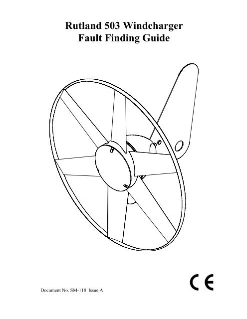
<strong>Rutland</strong> <strong>503</strong> <strong>Windcharger</strong><br />
<strong>Fault</strong> <strong>Finding</strong> <strong>Guide</strong><br />
Document No. SM-118 Issue A
INTRODUCTION<br />
This manual contains important information concerning fault<br />
finding on your <strong>Rutland</strong> <strong>503</strong> <strong>Windcharger</strong>.<br />
It is strongly recommended that you read this manual and<br />
familiarise yourself with its contents before attempting to<br />
repair the <strong>Windcharger</strong> system.<br />
To use this fault finding guide, open out this flow chart, select<br />
the symptom in the left hand column & follow the arrows &<br />
instructions.<br />
WARNING!<br />
• When turning, the <strong>Windcharger</strong> is capable of generating<br />
voltages in excess of the nominal voltage. Caution must be<br />
exercised at all times to avoid electric shock.<br />
• No attempt to repair the system should be made until the<br />
wind generator is restrained from turning.<br />
• The <strong>Windcharger</strong> is fitted with ceramic magnets which can<br />
be damaged by heavy handling. The main generator assembly<br />
should be treated with care during transit and assembly.<br />
• It is essential to observe the correct polarity when<br />
connecting the <strong>Windcharger</strong> and all other components into an<br />
electrical circuit. Reverse connection will damage the<br />
<strong>Windcharger</strong> and incorrect installation will invalidate the<br />
warranty.<br />
• If in doubt, refer to your dealer, a competent electrical<br />
engineer or the manufacturer.
WG<strong>503</strong> <strong>Fault</strong> <strong>Finding</strong> <strong>Guide</strong><br />
Notes:<br />
1. Insufficient Wind / Turbulence<br />
Please see page 4 of the WG<strong>503</strong> Owners Manual “Siting the <strong>Windcharger</strong>”-<br />
Document No SM-115 supplied with the WG<strong>503</strong>.<br />
2. Turbine Not Turning<br />
A. Check for a short circuit in the system. Ensure there are no wires trapped or<br />
shorted to the supporting pole or other earth on the system. Ensure all wiring is<br />
connected correctly and securely.<br />
B. Check that the generator hub is running freely by rotating the hub by hand. If it<br />
does not, it could be due to a mechanical defect inside the hub. If the hub produces<br />
a rumbling sound, this could be due to faulty bearings which should be replaced.<br />
3. Check Brushes and Slipring<br />
• Remove the generator from it’s mounting & place it face down on a suitable flat<br />
surface.<br />
• Remove the 2 screws which secure the tail fin in place, remove the tail fin. Slide<br />
the nacelle from the protruding semi-circular casting to expose the rectifier<br />
assembly.<br />
• Remove each brush holder cap in turn & withdraw the carbon brush.<br />
Check the brushes for signs of damage or overheating, overheating indicates that at<br />
some time the battery has been connected with reverse polarity.<br />
• Replace brushes if necessary.<br />
• Replace the brush holder caps tightly.<br />
4. Check Battery Condition.<br />
• Check that the battery voltage is correct for the system.<br />
• Check the battery terminal voltage.<br />
• Check electrolyte level if a non-sealed battery is fitted.<br />
5. Check Regulator.<br />
This section applies to the SR60 regulator. If you have a RWS60 or other regulator,<br />
please refer to the regulator manual.<br />
Before attempting to bench test the regulator, disconnect it from the system & reconnect<br />
the wind generator directly to the battery, if the system now charges as<br />
expected this indicates that the regulator is at fault, if the symptoms are still<br />
unchanged then this indicates the fault is elsewhere.<br />
In order to check the regulator it is necessary to use a variable d.c power supply<br />
together with a voltmeter and ammeter, if this equipment is not available the regulator<br />
must be returned to the manufacturer.<br />
• Connect the Black lead of the SR60 to the negative of the power supply.<br />
• Connect both the Brown and the Red leads of the SR60 to the positive of the<br />
power supply.<br />
Document SM-118 Issue A<br />
<strong>Marlec</strong> <strong>Engineering</strong> Co Ltd
WG<strong>503</strong> <strong>Fault</strong> <strong>Finding</strong> <strong>Guide</strong><br />
• Slowly increase the voltage of the power supply until 13.8v is reached, at this point<br />
the regulator will begin to draw current, a further increase of the power supply<br />
voltage will cause the Regulator to draw more current.<br />
• The built in blocking diode can be checked using a multimeter set to Ohms range<br />
applied between the Red & Brown leads of the Regulator. Positive lead to Brown,<br />
negative lead to Red should show continuity. Positive lead to Red, negative lead to<br />
Brown should show no continuity.<br />
• If the Regulator does not operate as above it should be returned to the<br />
manufacturer or replaced.<br />
6. Check Rectifier.<br />
• It is first necessary to remove the generator and it’s nacelle cover as in Note 3.<br />
• Un-solder the 3 stator output leads from the rectifier.<br />
• Using a multimeter on Ohms range, the rectifier can be tested as follows.<br />
Red lead to +ve brush holder, Black lead to each a.c terminal - No Continuity<br />
Black lead to +ve brush holder, Red lead to each a.c terminal - Continuity<br />
Red lead to -ve brush holder, Black lead to each a.c terminal - Continuity<br />
Black lead to -ve brush holder, Red lead to each a.c terminal - No Continuity<br />
+VE<br />
AC<br />
AC<br />
-VE<br />
• If the rectifier does not check out as above it should be replaced.<br />
• Re-solder the 3 stator output leads to the rectifier.<br />
7. Check Winding.<br />
• It is first necessary to remove the generator and it’s nacelle cover as in Note 3.<br />
• De-solder the 3 stator output leads from the rectifier.<br />
• Using a multimeter on Ohms range or an Ohmeter, measure the resistance between<br />
2 of the 3 leads, the reading should be approx 1.8Ω at 20°C.<br />
• Repeat the process for each combination of 2 leads, in each case the readings<br />
should be approximately the same.<br />
• If the resistance measured is greatly different from above, the winding should be<br />
replaced.<br />
Document SM-118 Issue A<br />
<strong>Marlec</strong> <strong>Engineering</strong> Co Ltd
WG<strong>503</strong> <strong>Fault</strong> <strong>Finding</strong> <strong>Guide</strong><br />
8. Check System Wiring<br />
• Check all wiring & connections between the wind generator, regulator and<br />
battery for damage, corrosion & open circuit or poor/loose connections.<br />
Document SM-118 Issue A<br />
<strong>Marlec</strong> <strong>Engineering</strong> Co Ltd
WG<strong>503</strong> <strong>Fault</strong> <strong>Finding</strong> <strong>Guide</strong><br />
Exploded View 1. Main assemblies.<br />
Item No Description <strong>Marlec</strong> Part No<br />
1 Nose Dome 05-034<br />
2 Hub assembly (Exploded view 2) SA-50/10<br />
Including: Magnet assembly Qty 2(Item 9)<br />
Turbine Blade (Item 10)<br />
Bearings Qty 2 (Item 11)<br />
Stator Winding (Item 12)<br />
3 Nacelle Back Plate 05-035<br />
4 Wind Shaft casting Assembly (Exploded view 3) SA-50/13<br />
Including: Windshaft casting<br />
Brush Holder/Brush kit (item 13)<br />
5 Post Adaptor assembly SA-50/14<br />
Including: Post Adaptor<br />
Post Shaft<br />
Bearing (Item 15)<br />
Bearing (Item 16)<br />
Slipring (Item 17)<br />
Associated fasteners<br />
6 Rectifier assembly SA-50/16<br />
7 Nacelle 05-031<br />
8 Tail assembly SA-50/15<br />
Items above with Part Nos prefixed ‘SA’ are supplied ready assembled.<br />
Document SM-118 Issue A<br />
<strong>Marlec</strong> <strong>Engineering</strong> Co Ltd
WG<strong>503</strong> <strong>Fault</strong> <strong>Finding</strong> <strong>Guide</strong><br />
Components of assemblies with Item numbers are available separately.<br />
Exploded view 2. Hub assembly<br />
Item No Description <strong>Marlec</strong> Part No<br />
9 Magnet assembly (pair) SA-50/12<br />
10 Turbine Blade 05-001<br />
11 6002ZZ bearing (2 per hub) 921-014<br />
12 Stator winding (including bearings) SA-50/11<br />
Document SM-118 Issue A<br />
<strong>Marlec</strong> <strong>Engineering</strong> Co Ltd
WG<strong>503</strong> <strong>Fault</strong> <strong>Finding</strong> <strong>Guide</strong><br />
Exploded view 3. Wind shaft casting assembly<br />
Item No Description <strong>Marlec</strong> Part No<br />
13 Brush Holder/Brush Kit SA-10/04<br />
14 Brush 4x4x15 (2 per unit) 917-001<br />
Exploded view 4. Post adaptor assembly.<br />
Item No Description <strong>Marlec</strong> Part No<br />
15 6000ZZ bearing 921-009<br />
16 6202ZZ bearing 921-001<br />
17 Slipring 919-001<br />
Document SM-118 Issue A<br />
<strong>Marlec</strong> <strong>Engineering</strong> Co Ltd


