Rutland 914i Windcharger Owners Manual - Marlec Engineering Co ...
Rutland 914i Windcharger Owners Manual - Marlec Engineering Co ...
Rutland 914i Windcharger Owners Manual - Marlec Engineering Co ...
- No tags were found...

You also want an ePaper? Increase the reach of your titles
YUMPU automatically turns print PDFs into web optimized ePapers that Google loves.
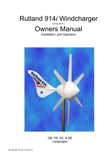
<strong>Rutland</strong> <strong>914i</strong> <strong>Windcharger</strong>Installation & Operation<strong>Rutland</strong> <strong>914i</strong> <strong>Windcharger</strong>(12 or 24 V )<strong>Owners</strong> <strong>Manual</strong>Installation and OperationGB, FR, ES & DELanguagesDoc No:SM-137 Iss. C 13.02.13 1 <strong>Marlec</strong> Eng <strong>Co</strong> Ltd
<strong>Rutland</strong> <strong>914i</strong> <strong>Windcharger</strong>Installation & OperationDoc No:SM-137 Iss. C 13.02.13 2 <strong>Marlec</strong> Eng <strong>Co</strong> Ltd
<strong>Rutland</strong> <strong>914i</strong> <strong>Windcharger</strong>Installation & Operation<strong>Co</strong>ntentsPage:Introduction 4Summary of Features and Uses 4Profile and Dimensions 4General Guidelines and Warnings 5Check You Have Received 6Other Items 7Exploded View of the <strong>Rutland</strong> <strong>914i</strong> 7Assembly & InstallationTwelve Step Quick Start Guide 8Tower Preparation 9Blade Assembly 9Tail and Nose Assembly 10Electrical <strong>Co</strong>nnection & Fitting to the Tower 11Up & RunningFour Point Checklist 11Typical Wiring Diagrams for the <strong>Rutland</strong> <strong>914i</strong> <strong>Windcharger</strong> 12Siting the <strong>Windcharger</strong>General <strong>Co</strong>nsiderations 13Mounting The <strong>Windcharger</strong>On Board Systems 14Land Based Systems 15Further System RequirementsBatteries 16Cable Specifications 16Specification & PerformanceGuideline Performance Curve 17Maintenance & TroubleshootingInspection & Maintenance 18Troubleshooting 19Installation Instructions (abbreviated) - French 21Installation Instructions (abbreviated) - Spanish 24Installation Instructions (abbreviated) - German 27For Your Records 30Limited Warranty 31Doc No:SM-137 Iss. C 13.02.13 3 <strong>Marlec</strong> Eng <strong>Co</strong> Ltd
<strong>Rutland</strong> <strong>914i</strong> <strong>Windcharger</strong>Installation & OperationIntroduction<strong>Co</strong>ngratulations and thank you for purchasing your <strong>Rutland</strong> <strong>914i</strong> <strong>Windcharger</strong>.The utmost of care goes into the manufacture of all our products in our ISO9001approved factory. To ensure you get the very best out of the <strong>Rutland</strong> <strong>914i</strong> werecommend that you read this manual and familiarise yourself with its contentsbefore installing and operating the <strong>Windcharger</strong> system.Summary of Features and Uses Aerodynamically improved to maintain good wind flow and stability. Maximum power point tracking technology yields up to 30% more power thanthe <strong>Rutland</strong> 913. Low wind speed start up maximises power generation in low winds. High grade construction materials for durability, U.V. stability and weatherresistance. Provides a D.C. power supply to charge 12 or 24 V battery banks. Designed for use on board sailing yachts, motor caravans, static caravansand sites where low power is needed for domestic devices as well asnavigation equipment etc. Note: There are other <strong>Rutland</strong> <strong>Windcharger</strong>s designed for permanentinstallations on land - contact <strong>Marlec</strong> or visit www.marlec.co.uk to find outmore.<strong>Rutland</strong> <strong>914i</strong> Profile & DimensionsFig 1Doc No:SM-137 Iss. C 13.02.13 4 <strong>Marlec</strong> Eng <strong>Co</strong> Ltd
<strong>Rutland</strong> <strong>914i</strong> <strong>Windcharger</strong>Installation & OperationGeneral Guidelines & Warnings Mounting pole outside diameter MUST NOT exceed 48.5mm for at least thetop 0.5m. Larger section poles must not be used as this will reduce the towerto blade clearance. In high wind conditions this could cause damage to the<strong>Windcharger</strong> by allowing the blade to come into contact with the mountingpole. A broken blade will cause turbine imbalance with consequent damage. When turning, the <strong>Windcharger</strong> is capable of generating voltages in excess ofthe nominal voltage. The turbine must never be allowed to rotate unless it iselectrically connected to a regulator or batteries. <strong>Co</strong>nnecting an open circuitrunning turbine to the electrical system can cause serious damage to systemcomponents owing to excessive voltage. Caution must be exercised at alltimes to avoid electric shock. Stopping the turbine – this may be necessary to undertake batterymaintenance. If possible stopping the turbine should be done in low windspeed conditions. The turbine can be slowed by rotating or orienting the tail finupwind, this will slow the turbine sufficiently for it to be safely secured to thepole with rope. Avoid leaving the turbine tied up for any period of time, werecommend that the turbine either be covered to give protection from theweather or removed and stored in a dry location. We recommend the use of<strong>Marlec</strong> charge regulator that includes a shutdown switch. Choose a calm day to install the equipment and consider other safety aspects.No attempt to repair the system should be made until the wind generatorsrestrained from turning. The <strong>Windcharger</strong> is fitted with ceramic magnets, which can be damaged byheavy handling. The main generator assembly should be treated with careduring transit and assembly. It is essential to observe the correct polarity when connecting the <strong>Windcharger</strong>and all other components into an electrical circuit. Reverse connection willdamage the <strong>Windcharger</strong> and incorrect installation will invalidate the warranty.Doc No:SM-137 Iss. C 13.02.13 5 <strong>Marlec</strong> Eng <strong>Co</strong> Ltd
<strong>Rutland</strong> <strong>914i</strong> <strong>Windcharger</strong>Installation & OperationThe fuse supplied must be fitted to protect the system. The <strong>Rutland</strong> <strong>914i</strong> <strong>Windcharger</strong> is suitable for sailing boats and some landbased applications. When storm winds are forecast the turbine can be restrainedto minimise wear and tear particularly when installed on land basedapplications where Furlmatic model windchargers are normally recommended.Note that where the manufacturer recommends a furling type windchargershould have been used the warranty is invalidated in cases of storm damage. If in doubt, refer to your dealer, a competent electrical engineer or themanufacturer.Check You Have Received - See <strong>Rutland</strong> <strong>914i</strong> Exploded View 24 x No.10x25mm special self-tapping screws for aerofoil blades 1 x No.4 x 13mm self tapping screw for tail bracket covers 2 x M6 x 16mm hex. Head screws for tail fin 2 x M6 nylock nuts for tail fin 1 x fuse and fuse holder 1 x main generator assembly 6 x aerofoil blades 1 x tail fin 2 x tail bracket covers 1 x nose cone + 3 x nylon fixing screws 1 x 6mm Allen key 1 x 2-way terminal block 2 x M10 buttoncap screws 2 x shakeproof washersIn the event of loss or damage, consult your dealer or the manufacturer.Doc No:SM-137 Iss. C 13.02.13 6 <strong>Marlec</strong> Eng <strong>Co</strong> Ltd
<strong>Rutland</strong> <strong>914i</strong> <strong>Windcharger</strong>Installation & OperationOther ItemsWhat You Will Need - Tools Suitable wire stripper Small terminal screwdriver Large flat blade screwdriver Crosshead screwdriver 10mm Spanner or SocketOther Items You Will Need Mounting pole Cable Batteries Battery terminals <strong>Co</strong>nnector blocks (as determinedby your total system)Other Items You May Have Selected HRSi or HRDi Charge Regulator Cable (usually 2.5mm² twin core - Part No: 902-015) <strong>Rutland</strong> <strong>914i</strong> Marine Mounting Kit and Stays Kit ( CA-12/02 & CA-12/32 ) <strong>Rutland</strong> <strong>914i</strong> Land Tower & Rigging Kit (Part Nos: CA-12/08 & CA-12/07) Short section of stainless steel tube to adapt into your own mounting design. Voltmeter & AmmeterExploded View of The <strong>Rutland</strong> <strong>914i</strong>Nacelle DomeSix Blades withTwenty FourTail finNose <strong>Co</strong>neWith ThreeScrewsPost AdaptorGenerator HubDoc No:SM-137 Iss. C 13.02.13 7 <strong>Marlec</strong> Eng <strong>Co</strong> Ltd
<strong>Rutland</strong> <strong>914i</strong> <strong>Windcharger</strong>Installation & OperationAssembly and InstallationTwelve Step Quick Start Guide1. Choose an open site to expose the <strong>Windcharger</strong> to a clear flow of wind and avoidingobstructions. On board mount the <strong>Windcharger</strong> at least 2.4 metres above the deck andon land at least 4 - 6 m high. Read the full section on Siting.2. Choose a mounting pole with an internal diameter of 41.0mm and externaldiameter of no greater than 48.5 mm for the top 0.6m minimum to (i) preventaccidental damage and (ii) meet warranty conditions.3. Mount a charge regulator, from the <strong>Marlec</strong> range, to a suitable vertical surfaceand close to the battery. Follow instructions supplied with the charge regulator.4. Drill the mounting pole, if required, in preparation to accept and secure the<strong>Windcharger</strong>. See Assembly and Installation section.5. Choose suitable two core cable to connect from the <strong>Windcharger</strong> to the regulator. Upto 20m this should be of at least 2.5mm² cross sectional area. A short section of 4mm²cross sectional area is required to link the regulator to the battery. For other distancessee the table in Cable Specifications.6. Position the mounting pole ( this may be done on the ground before raising thepole ) so that the selected cable can be threaded along it.7. Fit the blades, tail and nose to the <strong>Windcharger</strong> using fasteners provided. It isessential that 4 screws are fitted per blade.8. Join the cable threaded through the pole to the <strong>Windcharger</strong> output cable usingthe connector block provided. Wrap with insulating tape. Alternatively use alatching plug and socket. We recommend looping back the cable and securingwith a cable tie to provide strain relief to the joint.9. Carefully push the cables down the pole whilst sliding the post adaptor downthe pole. Line up the holes and secure in place with the screws and washersprovided. Tighten with the Allen key. Do not allow the turbine to spin freely.10.Locate the charge regulator close to the battery and carefully follow ALL theregulator guidelines and installation sequences for connecting the <strong>Windcharger</strong>through to the battery. Note : Install the in-line fuse supplied with the<strong>Windcharger</strong> between the battery and charge regulator.11.Ensure that the battery connections are permanent as the <strong>Windcharger</strong> shouldNEVER be operated without a connection to the battery.12.Raise and secure the <strong>Windcharger</strong>. It can now be allowed to rotate. Follow the“ Up and Running- Four Points Final Checklist” featured later. Also the“ General Guidelines and Warnings” section expands on the above points.Doc No:SM-137 Iss. C 13.02.13 8 <strong>Marlec</strong> Eng <strong>Co</strong> Ltd
<strong>Rutland</strong> <strong>914i</strong> <strong>Windcharger</strong>Installation & OperationAssembly and Installation Detailed InstructionsFig.2Tower Preparation (Fig.2)1. Select a suitable pole from the suggestedguidelines in Mounting the <strong>Windcharger</strong>.Note that the post adapter fitted to the <strong>914i</strong>is designed to fit inside a standard 41mm(1”) internal diameter tube.The adapter is provided with a flat on oneside to clear the weld seam on seamed pipe.2. Mark and centre-punch two positions diametrically opposite, at 90° to the pipeseam if necessary, 20mm from top of the tubeNote: Use metric measurements for this operation3. Drill two holes 10.5mm in diameter on centre-punch positions.Note :Use metric measurements for this operationNote: When using <strong>Rutland</strong> <strong>914i</strong> Mounting Kit , items 2 and 3 can be ignored as<strong>Marlec</strong> supplied poles are pre-drilled.Fig. 3Blade Assembly (Fig.3)1. Place the generator assembly on a flatsurface hub-side down. Position blade asshown. The blades will only fit one wayaround.2. Insert the protrusion at the trailing edge ofthe blade root fixing first into the socket toalign with the corresponding recess in theblade socket. The blade can then beinserted with a lever action. A soft facedmallet may be used to tap the end of the3. First fit each blade with two special self-tapping screws provided to the rear ofeach blade by inserting each in turn through the cut out in the nacelle, rotatingthe generator each time until the holes align. Fit the remaining blade screwsfrom the front of the generator hub. Check tightness of all screws but do notover-tighten. Caution- It is essential that all 4 screws are fitted!Alternatively the blades, tail and nose dome can be fitted after mounting thegenerator assembly to the tower.Doc No:SM-137 Iss. C 13.02.13 9 <strong>Marlec</strong> Eng <strong>Co</strong> Ltd
<strong>Rutland</strong> <strong>914i</strong> <strong>Windcharger</strong>Installation & OperationFitting The Tail and Nose Assembly (Fig.4)1. Slide the tail fin between the two tail brackets lining up all drilled holes.2. Locate the two screws provided through the appropriate holes and securewith nuts.3. Locate the tail bracket covers into the nacelle grommet whilst positioningthe processes for the fixing screw into the appropriate drilled hole in thetail.4. Secure with the self tapping screw provided.Tail Bracket <strong>Co</strong>versTail BracketsTail FinNacelleFig.44. Fit the plastic nose dome in position on the front of the generator hub andsecure in place with the three nylon screws provided.5. You may now mount the <strong>Rutland</strong> <strong>914i</strong> on to the tower if you have notalready done so.Doc No:SM-137 Iss. C 13.02.13 10 <strong>Marlec</strong> Eng <strong>Co</strong> Ltd
<strong>Rutland</strong> <strong>914i</strong> <strong>Windcharger</strong>Installation & OperationElectrical <strong>Co</strong>nnection and Fitting to The Tower1. Run the cable selected (see Table 1) down the inside of the pole.2. Select one of the 2 basic wiring systems on page 12 and follow the manualprovided with the voltage controller.3. <strong>Co</strong>nnect the wind generator flying leads to the cable protruding from thetower using the connector block supplied, taking care to observe polarity.<strong>Co</strong>nnect the <strong>Windcharger</strong> + to cable + and windcharger – to cable –Red is + PositiveBlack is - Negative4. Wrap the connection with insulation tape to secure/protect from environment.Alternatively join the cables using a latching-type plug and socket.5. Locate the wind generator into the tower whilst gently easing the cable fromthe tower base to ensure the cable is not trapped. Secure the wind generatorto the tower using the button cap screws and shake proof washers provided,tighten using the 6mm Allen key provided.Up and RunningFour Point Final ChecklistBefore raising and securing the wind generator:1. Check the tightness of the blade & tail fixing screws and generator mountingscrews.2. Check free rotation of the hub and yaw axis.3. Check that the cable is not trapped.4. Check that all electrical connections are secure and safe.The wind generator can now be raised into position.Take care to avoid all moving parts when raising and lowering the windgenerator.When raised, secure the structure firmly in an upright position.Caution-The performance of your <strong>Windcharger</strong> will be impaired if the pole isnot vertical.Doc No:SM-137 Iss. C 13.02.13 11 <strong>Marlec</strong> Eng <strong>Co</strong> Ltd
<strong>Rutland</strong> <strong>914i</strong> <strong>Windcharger</strong>Installation & OperationTypical Wiring Diagrams For The <strong>Rutland</strong> <strong>914i</strong> <strong>Windcharger</strong>Solar PanelMaximum160 WattsHRSi ChargeRegulator12/24 VTypical Wiring Scheme For A Single Battery BankTypical Wiring Scheme For Single or Dual Battery BanksSolar PanelMaximum160 WattsHRDi ChargeRegulator12/24 VIn-Line FuseSecond batteryoptionalDoc No:SM-137 Iss. C 13.02.13 12 <strong>Marlec</strong> Eng <strong>Co</strong> Ltd
<strong>Rutland</strong> <strong>914i</strong> <strong>Windcharger</strong>Installation & OperationSiting The <strong>Windcharger</strong>General <strong>Co</strong>nsiderationsThe location and height of the mounting pole or tower for your wind turbine willbe the major factor in the overall performance of your system. The smooth flowof wind over land and water is often interrupted by a multitude ofobstructions causing wind sheer and turbulence.Wind shear describes the interference between the fast moving upper air andthe slow moving air close to the ground and the resulting decrease in averagewind speed as one gets closer to the ground.Turbulence is caused by the wind passing over obstructions such as mooredboats, trees, and buildings.Both wind sheer and turbulence diminish with height and can be overcomesimply by putting the turbine sufficiently high above them as shown in Fig 4.Wind speed decreases and turbulence increases where obstructions exist.<strong>Co</strong>nsider also that downwind obstructions can be as detrimental to performanceas upwind obstructions.It is therefore essential that the wind generator should be located in an area asfree as possible from disturbed wind flow.Fig. 4WIND DIRECTIONAREA OF TURBULENCEH2H2H20HDoc No:SM-137 Iss. C 13.02.13 13 <strong>Marlec</strong> Eng <strong>Co</strong> Ltd
<strong>Rutland</strong> <strong>914i</strong> <strong>Windcharger</strong>Installation & OperationMounting The <strong>Windcharger</strong>Fig. 5On Board SystemsThe wind generator should be mounted in a safeposition, a minimum of 2.3 metres (7.6 feet) abovethe deck and away from other obstacles whichcould interfere with the blades or tail assembly (Fig.5).Fig. 6The <strong>Rutland</strong> <strong>914i</strong> Mounting & Stays Kits (Part No.CA-12/02 & CA-12/32) are available for deckmounting, or short sections of stainless steel tubeof 1200mm (47”) and 600mm (23”) pre-drilled arealso available for your own fabrication.The <strong>Rutland</strong> <strong>914i</strong> is designed to fit inside analuminium or stainless steel tube with an internaldiameter of 41mm (1”). IMPORTANT: Theexternal diameter MUST NOT exceed 48.5mm(1), see Warning in Introduction.Suitable tubes: Stainless Steel 1 3 / 4 ”16 SWG andAluminium 1 7 / 8 ” 10 SWGFig. 7We suggest the following mountings according topreference and site conditions:-Push pit (Fig.6)A suitable pole mounted to the deck with deckplates and solid guys is the most popular method ofmounting the <strong>Windcharger</strong> on yachts, eg. <strong>Rutland</strong>913 Mounting & Stays Kit.Fig. 8Mizzen (Fig.7)Mizzen mounting is suitable on larger yachts,taking advantage of greater wind flow the higherthe wind turbine is mounted.River Boats (Fig.8)A pivot pole is ideal for riverboats as the<strong>Windcharger</strong> can easily be raised and lowered.Doc No:SM-137 Iss. C 13.02.13 14 <strong>Marlec</strong> Eng <strong>Co</strong> Ltd
<strong>Rutland</strong> <strong>914i</strong> <strong>Windcharger</strong>Installation & OperationFig. 9Centre pivoted poleFig. 10Base pivoted with gin poleLand Based SystemsThe <strong>Rutland</strong> <strong>914i</strong> is suitable for some land basedtemporary and leisure applications. The Furlmatic<strong>Windcharger</strong> model is recommended for landbased remote and exposed locations.The <strong>Rutland</strong> <strong>914i</strong> is designed to fit insidealuminium, stainless or steel tube with an internaldiameter of 41mm. (1”). IMPORTANT: Theexternal diameter MUST NOT exceed 48.5mm(1), see Warning in Introduction.A suitable mounting pole can be erected using a6.5 metre (21 feet) galvanised (medium) tube.The tube must be supported by a minimum of fourguy lines. The attachment points for the guy linesto the tower should be securely fixed to the tower.The guy wires should be a minimum of 4mm(0.16”) in diameter.The shackles should be a minimum of 5mm(0.20”) in diameter.Rigging screws should be a minimum of 5mm(0.20”) in diameter.All items should be galvanised or stainlesssteel for protection against corrosion.Where guy lines are looped, the loop mustincorporate a thimble and be fitted with aminimum of three rope grips.All ground fixings must be made suitableaccording to the terrain.We suggest pivot type towers as these allow foreasier installation and lowering for access to thewind generator. Two forms of pivot tower aresuggested in Figs 9 & 10.A base-hinged 6.4m tall Land Tower Kit (PartNo: CA-12/08) and Rigging Kit (Part No:CA-12/07) are available from <strong>Marlec</strong>.Doc No:SM-137 Iss. C 13.02.13 15 <strong>Marlec</strong> Eng <strong>Co</strong> Ltd
<strong>Rutland</strong> <strong>914i</strong> <strong>Windcharger</strong>Installation & OperationFurther System RequirementsTotal = 12v120Ah1440Wh60Ah12v60Ah12vIn parallel to increase ampTotal = 24v60Ah1440Wh60Ah12v60Ah12vIn series to increase voltageBatteriesLeisure/Deep Cycle batteries are specificallydesigned for good performance in terms ofcharge/discharge cycles. Batteries are the mostimportant part of your battery charging systemand should be sized according to your loadrequirements and provide at least 3 daysreserve capacity. This will reduce cycling,prolong the life of the battery and ensuresystem reliability during periods of low wind.Permanent connections should always be madeto the battery terminals. Never use crocodileclips or similar devices.We strongly recommend that one of the voltageregulators available from <strong>Marlec</strong> is fitted toprevent batteries becoming overcharged instrong winds and is essential with gel/sealedbatteries.Batteries may be linked as shown in the figures10 and 11. It is essential to observe polarity asfollows:Red is + PositiveBlack is - NegativeCable SpecificationCable SizeCable 12V24VRun(m)mm² AWG mm² AWG0-20 2.5 13 1.5 1521-30 4 11 2.5 1331-45 6 9 4 1146-80 10 7 6 9The cable used for connection of the<strong>Windcharger</strong> to the batteries should be inaccordance with table 1. The use of asmaller cable than recommended willreduce the performance of the chargingsystem.Cable and connectors are available fromyour dealer or the manufacturer.Doc No:SM-137 Iss. C 13.02.13 16 <strong>Marlec</strong> Eng <strong>Co</strong> Ltd
<strong>Rutland</strong> <strong>914i</strong> <strong>Windcharger</strong>Installation & OperationSpecification and PerformanceGuideline Performance CurveNote : The curve shown below is for clear, non-turbulent wind conditions; thismay not be achieved in some installations. Refer to the section on Siting tooptimise performance at your site. Wind speeds are those flowing across theturbine of the <strong>Windcharger</strong> and may not reflect those measured at mast top orthose reported by the Met. Office.10987654321Charge into 24 V Battery (Amperes)Doc No:SM-137 Iss. C 13.02.13 17 <strong>Marlec</strong> Eng <strong>Co</strong> Ltd
<strong>Rutland</strong> <strong>914i</strong> <strong>Windcharger</strong>Installation & OperationMaintenance and TroubleshootingInspection and MaintenanceThe <strong>Rutland</strong> <strong>914i</strong> requires no scheduled maintenance but an annual inspectionshould be carried out to monitor the general condition of the system to ensurethe electrical and mechanical integrity and safety of the system.WARNING! Before inspection, the turbine should either be lowered to theground or tied to prevent the generator from turning. To stop the generator fromturning proceed as follows:1. Either rotate the switch to stall mode on the charge regulator if used OR turnthe wind generator out of the wind (180°) using the tail, a hole isprovided in the tail fin to assist in this. The generator will gradually slow down.2. Tie a blade to the mounting pole to prevent it from rotating.Whilst the generator is stationary, the following routine checks should beperformed:1. Check the blades for damage, eg chips or nicks. Replace any damagedblades. The turbine should not be operated with damaged blades as this maycause imbalance resulting in premature wear and possible failure. Check theblade screws for tightness.2. Check all other nuts, bolts and screws for tightness.3. Check the yaw axis for free rotation.4. Check tower assembly for condition.5. Check the tension of the guy wires if applicable. The tension of guy wiresshould be checked frequently during the first year.6. The unit can be wiped with a mild detergent and rinsed with water to removedirt and debris.Note: The <strong>Windcharger</strong> is designed for continuous running to achievemaximum resistance to water ingress. Should you wish to take theunit out of service for an extended period it is recommend that theunit be removed from the mounting and stored in a dry location orcovered.Doc No:SM-137 Iss. C 13.02.13 18 <strong>Marlec</strong> Eng <strong>Co</strong> Ltd
<strong>Rutland</strong> <strong>914i</strong> <strong>Windcharger</strong>Installation & OperationTroubleshootingIn the unlikely event that your <strong>Rutland</strong> <strong>914i</strong> should develop a defect, the turbineshould first be tied to prevent the blades from turning to perform the static testsbelow. (Follow the procedure described in the Inspection and Maintenancesection) It will be necessary to let it run for the tests to check for powerproduction.Read the Electrical <strong>Co</strong>nnection and Up and Running sections and be satisfiedthat your system complies.Is there sufficient wind? The <strong>Rutland</strong> <strong>914i</strong> needs 5 knots wind speed to startcharging. The wind speed across the turbine blades may be greatly reduced in amarina or built-up area compared with the reading on a masthead anemometeror weather reports.Static Tests:Is the battery in good condition? Check the voltage and electrolyte level ofeach battery.Check electrical continuity throughout the system, especially corrosion andpoor connections in cable joins and connector blocks.Running Tests:Check for power output from the windcharger, following this procedure:1. Set a digital multimeter to DC Amps, scale of between 5 and 10 if possible.<strong>Co</strong>nnect the meter positive (+) probe to the wind generator output positivecable and the meter negative (-) to the regulator input positive. Providedthere is sufficient wind there should be a current reading. This establishesthat power is being delivered.2. Using the same multimeter setting as above measure between the regulator tobattery + and the battery +. Provided there is sufficient wind there should be acurrent reading. This establishes if power is passing through the regulator.3. If both above are unsuccessful set the multimeter to DC Volts. Disconnect thewind generator from the regulator and connect the meter + to the windgenerator + and the meter – to the wind generator -. Provided there issufficient wind there should be a variable voltage reading according to thespeed of the wind seen at the wind turbine. This will establish if the windgenerator is able to deliver power or not.4. If tests 1 and 3 are successful but test 2 fails to produce results connect thewind generator directly to the battery. Set the digital multimeter to DC Ampsand measure power between the wind generator + and the battery +. If areading is measured, providing there is sufficient wind, then the regulator isfaulty.Doc No:SM-137 Iss. C 13.02.13 19 <strong>Marlec</strong> Eng <strong>Co</strong> Ltd
<strong>Rutland</strong> <strong>914i</strong> <strong>Windcharger</strong>Installation & Operation5. If the wind turbine fails to deliver any current or open circuit V readingundertake the further tests below.6. Mechanical inspection. It may be necessary to remove the windcharger fromits pole for the following tests.Check the brushes and slipring for wear or damage. To inspect the brushes,remove the nacelle by removing the three fixing screws and slide the nacellebackwards towards the tail fin. The brushes and slipring can be inspected byremoving the four self-tapping screws holding the brush holder assembly inplace. Remove any black deposits from slipring with emery paper. Heavy depositsand reduced power indicate a possible reverse connection to the battery(see Page 10).Check hub for free rotation with generator disconnected from battery.If the hub does not rotate freely, check for a possible short circuit in the wiring.If no wiring fault is found refer to your dealer or manufacturer.If the above checks have identified a need for spare parts or failed to identify theproblem you should contact <strong>Marlec</strong> who can advise you of your nearestdistributor in their world wide network. In the first instance we recommend thatyou contact the company from whom the product was originally purchased.If in doubt, refer to your dealer or manufacturer.Doc No:SM-137 Iss. C 13.02.13 20 <strong>Marlec</strong> Eng <strong>Co</strong> Ltd
<strong>Rutland</strong> <strong>914i</strong> <strong>Windcharger</strong>Installation & OperationIntroductionFrancaisFélicitations pour votre achat d’une éolienne <strong>Rutland</strong> <strong>914i</strong> ! <strong>Co</strong>mme tous nos produits, elle a étéfabriquée avec le plus grand soin, dans notre usine certifiée ISO 9001. Pour obtenir pleinesatisfaction de votre éolienne <strong>Rutland</strong> <strong>914i</strong>, nous vous recommandons de lire entièrement cemanuel et de vous familiariser avec son contenu avant de commencer l’installation ou de l’utiliser.Principales caractéristiques et applications <strong>Co</strong>nception aérodynamique pour une bonne prise au vent. Tourne avec peu de vent pour optimiser les performances même par vent faible. Matériaux de qualité pour une durée de vie optimale, une bonne résistance aux UV et auxconditions climatiques. Permet de charger des batteries 12V ou 24V. <strong>Co</strong>nçue pour fonctionner sur des bateaux, des camping-cars, des mobil-homes ou sur dessites où une faible puissance est nécessaire pour faire fonctionner des appareils ménagers, del’instrumentation, etc. NB : il existe d’autres modèles d’éoliennes conçues pour une installationterrestre permanente. Venez les découvrir sur notre site www.marlec.co.ukInformations générales et mises en garde Le diamètre externe du mât ne doit pas être supérieur à 48,5mm, au moins sur les 50 dernierscentimètres. Ne pas utiliser de mât plus gros au risque de réduire le jeu nécessaire entre lespales et le mât. En cas de vents forts, les pales risquent de heurter le mât et de s’endommager.Une pale brisée provoque un déséquilibre capable d’entraîner des dégâts importants. Lorsqu’elle fonctionne, l'éolienne peu générer de l'électricité à haute tension, c’est pourquoi ellene doit pas tourner tant qu’elle n’est pas reliée à un régulateur ou à des batteries. Raccorderdirectement l’éolienne à l’installation électrique peut provoquer des dégâts importants en raisonde la surtension. Pour éviter tout risque d’électrochoc, vous devez être constamment vigilant. Stopper l’éolienne – Cela peut s’avérer nécessaire avant d’intervenir sur les batteries. Dans lamesure du possible, il est préférable de le faire lorsque le vent est faible. L’éolienne peut alorsêtre ralentie en orientant l’aileron contre le vent ce qui permet de l’immobiliser en l’attachant aumât avec une corde. Éviter de l’immobiliser trop longtemps. Il est recommandé de la couvrirpour la protéger des effets du climat ou de la déposer pour l’entreposer en lieu sec. Lerégulateur HRDX, vendu en option, est équipé d’un interrupteur Marche/Arrêt. Entres autres éléments de sécurité, effectuer l’installation par temps calme. Aucune tentative de réparation ne doit être engagée tant que l'éolienne n'est pas immobilisée. L'éolienne est équipée d'aimants céramiques qui peuvent facilement être abîmés lors de leurmanipulation. Elle doit être maniée avec précaution durant le transport et le montage. Vents forts – Par vents forts, la sécurité thermique intégrée peut stopper l’éolienne pourl’empêcher de surchauffer. Dans ce cas, l’éolienne ne produit plus d’électricité et sa vitesse derotation peut ralentir et d’ augmenter, le temps nécessaire au refroidissement. Elle se remetautomatiquement en marche lorsque la température a baissé. Si les vents forts persistent etplus particulièrement par temps chaud, vous verrez ces cycles se répéter. S’il vous est possibled’accéder à l’éolienne en toute sécurité, il est préférable de la bloquer temporairement.Doc No:SM-137 Iss. C 13.02.13 21 <strong>Marlec</strong> Eng <strong>Co</strong> Ltd
<strong>Rutland</strong> <strong>914i</strong> <strong>Windcharger</strong>Installation & Operation Il est essentiel de respecter les polarités lors du branchement de l'éolienne ainsi quede tous les autres composants du système électrique. Inverser les branchementsendommagerait l'éolienne et une installation incorrecte annulerait la garantie. Le fusible fourni doit être installé pour protéger l'appareil. L’éolienne <strong>Rutland</strong> <strong>914i</strong> est conçue pour une utilisation sur des bateaux à voiles oucertaines applications terrestres. Lorsque des vents d’orage sont annoncés, l’éoliennepeut être immobilisée pour prévenir les risques d’usure et de casse, notammentlorsqu’elle est installée sur un site terrestre exposé aux vents forts pour lesquels il estrecommandé d’utiliser des modèles Furlmatic (avec mise en drapeau automatique).Si ce type d’éolienne est recommandé par le constructeur pour une application, maisqu’il n’en est pas tenu compte, la garantie ne fonctionnera en cas de dommagesoccasionnés par des vents forts.En cas de doute, se référer à votre revendeur, à un ingénieur compétent en électricitéou au fabricant.6 x Pâles et24 x Vis 10 x 25mmautotaraudeuses1 x Nacelle1 x <strong>Co</strong>rpsd’éolienne1 x Adapteur depoteau1 x Cône avant+3 vis de fixationDoc No:SM-137 Iss. C 13.02.13 22 <strong>Marlec</strong> Eng <strong>Co</strong> Ltd
<strong>Rutland</strong> <strong>914i</strong> <strong>Windcharger</strong>Installation & OperationGuide d’installation en douze étape1. Choisir un emplacement dégagé pour que l’éolienne soit exposée au vent sansaucune obstruction. A bord d’un bateau, la monter au minimum 2,5 m au-dessus dupont et sur terre à une hauteur de 4 à 6 m minimum. Lire le chapitre « Choix del’emplacement ».2. Prévoir un mât de 41 mm de diamètre intérieur et de 48,5 mm maximum de diamètreextérieur, au moins sur les 50 derniers centimètres, pour prévenir tout risque dedégâts et effectuer un montage conforme aux exigences de la garantie.3. Monter un régulateur, choisi dans la gamme proposée par <strong>Marlec</strong>, sur un plan verticalet à proximité des batteries. Suivre les instructions de montage fournies avec lerégulateur.4. Le cas échéant, percer les trous de fixation sur le mât et fixer l’éolienne au mât. Voir lechapitre « Assemblage et installation de l’éolienne ».5. Choisir un câble adéquat à deux conducteurs pour relier l’éolienne au régulateur.Jusqu’à 20 m de longueur, choisir un câble d’une section de 2,5 mm². Pour relier lerégulateur à la batterie, un câble de 4 mm² est nécessaire. Pour d’autres longueurs, sereporter au chapitre « Type de câble ».6. Passer le câble dans le mât (cela peut se faire au sol, avant de dresser le mât).7. Fixer les pâles, l’aileron et le cône avant sur l’éolienne, à l’aide des fixations fournies.Chaque pâle doit être montée avec les quatre vis fournies.8. Utiliser le bloc de connexion fourni pour raccorder le câble passé dans le mât au câblesur l’éolienne. Protéger la connexion avec du ruban isolant. Vous pouvez aussi utiliserune prise Nous recommandons d’effectuer une boucle et de la fixer afin de diminuer lacontrainte sur la connexion.9. Pousser les câbles à l’intérieur du mât avec précaution, et poser l’adaptateur dans lemât. Aligner les trous de fixation et sécuriser le montage avec les rondelles et les visfournies. Serrer en utilisant la clé Allen également fournie. Empêcher la turbine detourner à vide.10.Monter le régulateur à proximité de la batterie et suivre rigoureusement toutes lesinstructions ainsi que la séquence de branchements pour raccorder l’éolienne auxbatteries. NB : monter en ligne le fusible fourni avec l’éolienne entre le régulateur et labatterie.11.L’éolienne ne doit en aucun cas pouvoir fonctionner sans être raccordée à la batterie,s’assurer que la connexion soit permanente.12.Dresser et fixer le mât. L’éolienne est maintenant prête à fonctionner. Effectuer lesvérifications (en quatre points) indiquées au chapitre « Dressage et mise en service del’éolienne ». Les « Informations générales et mises en garde » énoncées ci-dessusdoivent également avoir été intégrées.Doc No:SM-137 Iss. C 13.02.13 23 <strong>Marlec</strong> Eng <strong>Co</strong> Ltd
<strong>Rutland</strong> <strong>914i</strong> <strong>Windcharger</strong>Installation & OperationIntroducciónEspañolFelicitaciones y gracias por comprar un cargador eólico <strong>Rutland</strong> <strong>914i</strong>.Utilizamos sumo cuidado en la fabricación de todos nuestros productos en nuestra fábricaaprobada por la Norma ISO9001. Para asegurarnos de que reciba lo mejor de nuestro <strong>Rutland</strong>913, le recomendamos que lea este manual y se familiarice con su contenido antes de instalar yponer en funcionamiento el sistema del cargador eólico.Resumen de características y usos estilo aerodinámico para mantener estabilidad y un buen flujo del viento el arranque con vientos a baja velocidad maximiza la producción de energía en vientos depoca fuerza materiales de construcción de gran calidad para mayor durabilidad, estabilidad U.V yresistencia a la intemperie proporciona una fuente de alimentación CC para cargar bancos de batería de 12 o 24 voltios. diseñado para ser utilizado a bordo de yates a vela, casillas rodantes motorizadas, casillasrodantes estáticas y sitios en donde se necesita una baja potencia para dispositivosdomésticos como así también equipos de navegación, etc. Nota: Existen otros cargadores eólicos <strong>Rutland</strong> diseñados para instalaciones permanentes entierra, para obtener mayor información, comuníquese con <strong>Marlec</strong> o visite la página Webwww.marlec.co.uk.Pautas y advertencias generales El diámetro externo del mástil de montaje NO DEBE exceder los 48,5 mm aunque sea en los0,5m superiores. No utilice mástiles más grandes ya que esto reducirá el espacio entre latorre y la paleta. En condiciones de vientos fuertes, esto puedo provocar daños al cargadoreólico ya que la paleta entra en contacto con el mástil de montaje. Una paleta rota produciráun desequilibrio en la turbina y daños posteriores. Al girar, el cargador eólico es capaz de generar voltajes superiores al voltaje nominal. Nuncapermita que la turbina gire a menos que se encuentre conectada eléctricamente a unregulador o a una batería. La conexión de una turbina que funciona con un circuito abierto alsistema eléctrico puede provocar daños graves a los componentes del sistema por elexcesivo voltaje. En todo momento, tenga cuidado y evite las descargas eléctricas. Detención de la turbina: puede ser necesaria para realizar el mantenimiento de la batería. Sies posible, detenga la turbina en condiciones de viento a baja velocidad. Disminuya lavelocidad de la turbina girando o dirigiendo la aleta de la cola contra el viento; esto diminuirála velocidad de la turbina lo suficiente como para que ésta se pueda sujetar con una soga ysin peligro al mástil. Evite dejar la turbina atada durante mucho tiempo; le recomendamosque cubra la turbina para protegerla de la intemperie o retírela y guárdela en un lugar seco.Le recomendamos que utilice el regulador de carga <strong>Marlec</strong> que incluye un interruptor dedesconexión. Elija un día sin viento para instalar el equipo y tenga en cuenta otros aspectos de seguridad. No intente reparar el sistema hasta que el generador de viento este sujeto y no pueda girar. El cargador eólico esta ajustado con imanes cerámicos que pueden dañarse durante unafuerte manipulación. Tenga cuidado con el ensamblaje del generador principal durante eltransporte y el montaje.Doc No:SM-137 Iss. C 13.02.13 24 <strong>Marlec</strong> Eng <strong>Co</strong> Ltd
<strong>Rutland</strong> <strong>914i</strong> <strong>Windcharger</strong>Installation & Operation Vientos fuertes: durante vientos fuertes el termostato incorporado al cargador eólicopuede ponerse en funcionamiento para evitar que el generador se recaliente. Eneste modo, la salida se detendrá y la turbina se desacelerará y acelerarátemporariamente hasta alcanzar una temperatura menor y el generador seencuentre nuevamente conectado y cargando. Se lo puede ver girar duranteprolongados vientos fuertes, particularmente en temperaturas ambientaleselevadas. Si es accesible y seguro, quizás prefiera sujetar temporariamente laturbina. Es esencial respetar la polaridad correcta al conectar el cargador eólico y todos losdemás componentes en un circuito eléctrico. Una conexión inversa dañará alcargador eólico y la instalación incorrecta anulará la garantía. Ajuste el fusible incluido para proteger el sistema. El cargador <strong>Rutland</strong> <strong>914i</strong> es apropiado para barcos de vela y algunas aplicacionesterrestres. Cuando se pronostica una tormenta de viento, se puede sujetar laturbina para minimizar el desgaste y daño particularmente cuando se encuentrainstalada en aplicaciones terrestres en donde normalmente se recomiendan losmodelos de cargadores eólicos Furlmatic. Tenga en cuenta que cuando elfabricante recomienda un cargador eólico plegable, la garantía se anulará en casosde daños por tormenta.1 x Cubierta6 x paletas y24 x 10x25torniillos1 x Adaptador del1 x Eje del generador1 x <strong>Co</strong>no de nariz y 3 x tornillosDoc No:SM-137 Iss. C 13.02.13 25 <strong>Marlec</strong> Eng <strong>Co</strong> Ltd
<strong>Rutland</strong> <strong>914i</strong> <strong>Windcharger</strong>Installation & OperationGuía rápida de inicio – 12 pasos1. Elija un sitio abierto para exponer al cargador eólico a un flujo libre de viento y así evitar obstrucciones.A bordo, monte el cargador eólico por lo menos a 2,4 metros de la cubierta, entierra por lo menos a 4 hasta 6 metros de altura. Lea toda la sección de Instalación.2. Elija un mástil de montaje con un diámetro interno de 41 mm y un diámetro externo no mayora 48,5 mm para los primeros 0,6 mm cómo mínimo para (i) evitar daños accidentales y (ii)cumplir con las condiciones de la garantía.3. Monte un regulador de carga, del rango <strong>Marlec</strong>, sobre una superficie vertical adecuada y cercade la batería. Siga las instrucciones proporcionadas con el regulador de carga.4. Perfore el mástil de montaje, en caso de ser necesario, para prepararlo para que tolere y sujeteal cargador eólico. Vea la sección Montaje e Instalación.5. Elija un cable de dos conductores adecuado para que el cargador eólico se conecte con elregulador. De hasta 20 m, éste debería ser un área de secciones de por lo menos 2,5 mm²Es necesaria una pequeña área de sección de 4 mm² para unir el regulador a la batería. Paraconsultar otras distancias, vea la clasificación en Especificaciones para cables.6. <strong>Co</strong>loque el mástil de montaje ( esto puede hacerlo en el piso antes de levantar el mástil) detal manera que el cable seleccionado pueda enroscarse a lo largo del mismo.7. Ajuste las paletas, la cola y la nariz del cargador eólico mediante los fijadores proporcionados.Es esencial que ajuste 4 tornillos por paleta.8. Una el cable enroscado en el mástil al cable de salida del cargador eólico mediante el bloqueconector proporcionado. Envuelva con cinta aisladora. O bien utilice un tapón o toma corrientecon pestillo. Le recomendamos enroscar el cable y asegurarlo con una cinta de sujeciónpara cables para aliviar la tensión en la junta9. <strong>Co</strong>n cuidado presione los cables hacia el mástil mientras desliza el adaptador del mástil porel mismo. Alinee los orificios y sujételos en el lugar con los tornillos y arandelas proporcionadas.Apriete con la llave Allen. No permita que la turbina gire libremente.10. Ubique el regulador de carga cerca de la batería y siga cuidadosamente TODAS las pautasy secuencias de instalación del regulador para conectar el cargador eólico a la batería. Nota:instale el fusible en línea proporcionado con el cargador eólico entre la batería y el reguladorde carga.11. Asegúrese de que las conexiones de la batería sean permanentes ya que el cargador eólicoNUNCA debe ponerse en funcionamiento sin estar conectado a la batería.12. Levante y sujete el cargador eólico. Ahora puede dejarlo que gire. Siga la “Lista de controlfinal de 4 puntos denominada: Instalado y en Funcionamiento”, que se observa másadelante. También la sección “Pautas y advertencias generales” amplía sobre los puntosmencionados.Doc No:SM-137 Iss. C 13.02.13 26 <strong>Marlec</strong> Eng <strong>Co</strong> Ltd
<strong>Rutland</strong> <strong>914i</strong> <strong>Windcharger</strong>Installation & OperationEinleitungDeutscheWir gratulieren und bedanken uns für den Erwerb Ihres <strong>Rutland</strong> <strong>914i</strong> <strong>Windcharger</strong>s. Wir leistendie beste Sorgfalt bei der Herstellung von allen unseren Geräten gemäß dem anerkanntenBetriebsstandard ISO9001. Zur Gewährleistung für alle Vorteile beim Gebrauch von <strong>Rutland</strong> <strong>914i</strong>bitten wir Sie diese Anleitung vollständig durchzulesen, bevor Sie mit der Montage undInbetriebnahme des <strong>Windcharger</strong>s fortfahren.Zusammenfassung der Funktionen und Anwendungen Aerodynamisch gestaltet für einen ausgezeichneten Luftstrom mit Luftstabilität. Das Anlassen bei einer niedrigen Windgeschwindigkeit maximiert Stromerzeugung bei geringenWindstärken. Hochwertige Baustoffe für Strapazierfähigkeit, UV-Strahlungsstabilität undWitterungsbeständigkeit. Der Wind Generator liefert eine Gleichstrom zum Aufladen eines 12 oder 24V Akku. Für die Nutzung auf Segeljachten an Bord, bei Reisemobilen, Wohnmobilen und für Standortebestimmt, wobei ein geringer Stromverbrauch für Haushaltsgeräte und auch fürNavigationsgeräte etc. erforderlich ist. Anmerkung: Für weitere <strong>Windcharger</strong> von <strong>Rutland</strong>, welche für die dauerhafte Montage an Ortund Stelle entworfen wurden, treten Sie bitte mit <strong>Marlec</strong> in Kontakt oder besuchen Siewww.marlec.co.uk für weitere Informationen.Allgemeine Richtlinien & Gefahrenhinweise Die Mastmontage DARF den Außendurchmesser von 48.5mm, zumindest den Oberen von0.5m NICHT überschreiten. Größere Mastquerschnitte dürfen nicht verwendet werden, da dieszu einer geringeren Distanz zwischen dem Mast und dem Rotorblattspiels führt. Bei hohenWindbedingungen könnte es beim <strong>Windcharger</strong> zu Schaden führen, da das Rotorblatt mit demfestmontierten Mast in Kontakt kommen könnte. Ein zerbrochenes Rotorblatt verursacht einUngleichgewicht der Turbine und dementsprechend Schäden. Bei der Drehbewegung ist der <strong>Windcharger</strong> in der Lage Stromspannungen höher als dieNennspannung zu erzeugen. Es darf nie zugelassen werden, dass die Turbine rotiert, es seidenn das sie elektrisch mit einem Aufladekontrollgerät oder mit Batterien angeschlossen ist.Der Anschluss einer laufenden Turbine im Leerlauf an das Elektrosystem kann ernsthafteSchäden bei den Anlagebestandteilen, aufgrund der überhöhten elektrischen Spannunghervorrufen. Vorsicht ist stets zu bewahren zur Vermeidung eines Stromschlages. Das Anhalten der Turbine – wird bei der Wartung der Batterie notwendig. Falls möglich solltedie Turbine bei Bedingungen mit niedrigen Windgeschwindigkeiten gestoppt werden. DieTurbine kann durch das Rotieren oder durch das windwärts legen der Heckschaufel desRotorblattes abgebremst werden, das führt zu einem Anhalten der Turbine, sodass sie sichermit einem Seil an den den Mast befestigt werden kann. Vermeiden Sie, dass die Turbine fürlängere Zeit festgebunden bleibt, wir empfehlen stattdessen, dass die Turbine entwederabgedeckt wird, um sie gegen die Witterung zu schützen oder entfernt und in einem trockenenRaum gelagert wird. Wir empfehlen den Nutzen des <strong>Marlec</strong> Aufladekontrollgerätes mit einemintegrierten Schalter zur Stromabschaltung. Wählen Sie einen windstillen Tag für die Montage der Anlage und beachten Sie dabei weitereSicherheitsfaktoren. Es darf kein Reparaturversuch an der Anlage stattfinden, bis alle Drehbewegungen desWindgenerators gedrosselt sind.Doc No:SM-137 Iss. C 13.02.13 27 <strong>Marlec</strong> Eng <strong>Co</strong> Ltd
<strong>Rutland</strong> <strong>914i</strong> <strong>Windcharger</strong>Installation & Operation Der <strong>Windcharger</strong> ist mit einem Keramikmagnet ausgestattet, der bei einer schwerwiegendenHandhabung beschädigt werden kann. Der Hauptstromgenerator sollte mit Sorgfalt währenddem Transport und der Montage behandelt werden. Hohe Windstärken – bei hohen Windstärken kann sich das eingebaute Thermostat des<strong>Windcharger</strong>s in Betrieb setzten, um ein Überheizen des Stromgenerators zu verhindern.Während diesem Betriebszustand wird die Ausgabe des Stromgenerators beendet, das Tempoder Turbine wird sich zeitweise verslangsamen und beschleunigen bis zu diesem Zeitpunkt,wenn die niedrigen Temperaturwerte erreicht wurden, dann wird der Stromgenerator erneutangeschlossen und aufgeladen. Dies lässt sich möglicherweise in geschlossener Reihe beilanganhaltenden hohen Windstärken ersehen, insbesondere bei hohen Außentemperaturen.Falls ein Zugriff ohne Gefahr möglich ist, wird es bevorzugt die Turbine zeitweise abzusichern. Es ist notwendig die korrekte Polarität zu beachten, wenn der <strong>Windcharger</strong> und alle weiterenBestandteile an den elektrischen Stromkreis angeschlossen werden. Ein Rückwärtsstrom wirdden <strong>Windcharger</strong> beschädigen und eine inkorrekte Installation führt dazu, dass die Garantiegegenstandslos gemacht wird. Die mitgelieferte Sicherung muss zum Schutz des Gerätes angebracht werden. Der <strong>Rutland</strong> <strong>914i</strong> <strong>Windcharger</strong> eignet sich für Segelboote und für einige Anwendungen zuLand. Wenn Sturmwinde vorhergesagt werden, kann die Turbine gedrosselt werden, um einenVerschleiß und Abnutzen zu reduzieren, insbesondere wenn sie für Anwendungen zu Landeinstalliert wurde, wobei dafür normalerweise die <strong>Windcharger</strong> der Furlmatic Modelle empfohlenwerden. Anmerkung, wenn es vom Hersteller empfohlen wurde, dass ein <strong>Windcharger</strong> der FurlmaticModelle für jegliche Art von Segelvorrichtungen zu nutzen sei, wird die Garantie im Falle einesSturmschadens gegenstandlos gemacht.Im Zweifelsfall wenden Sie sich bitte an Ihren Fachhändler, an einen fachkundigenElektroingenieur oder an den Hersteller.6 x Rotorblatter und24 x Schrauben1 x Haube1 x Nase und3 x Schrauben1 x Pfosten Adapter1 x GeneratornabeDoc No:SM-137 Iss. C 13.02.13 28 <strong>Marlec</strong> Eng <strong>Co</strong> Ltd
<strong>Rutland</strong> <strong>914i</strong> <strong>Windcharger</strong>Installation & OperationKurzanleitung mit zwölf Anhaltspunkten1. Wählen sie eine offene Stelle für die Montage Ihres <strong>Windcharger</strong>s in einem bestimmtenLuftstrom und unter der Vermeidung von Hindernissen. An Bord sollte der <strong>Windcharger</strong>mindestens 2.4 Meter über dem Deck und zu Lande mindestens 4 - 6 Meter hochangebracht werden. Lesen Sie den vollständigen Absatz zu: An einer Stelle befestigen[Siting].2. Wählen Sie einen Mast mit einem Innendurchmesser von 41.0mm und einemAußendurchmesser von nicht größer als 48.5 mm und mindestens für den Oberen 0.6m,um (i)einen Nebenschaden zu vermeiden und (ii) die Bedingungen der Garantie zu erfüllen.3. Montieren sie eines der Aufladekontrollgeräte von der Firma <strong>Marlec</strong> an eine geeignetesenkrechte Oberfläche und in der Nähe der Batterie. Befolgen Sie die Anleitung, die mitdem Aufladekontrollgerät mitgeliefert wurde.4. Bohren Sie, falls erforderlich, in den Montagemast zur Vorbereitung der Befestigung undInbetriebnahme des <strong>Windcharger</strong>s. Siehe Montage und Installation [Assembly andInstallation].5. Wählen sie ein geeignetes zweiadriges Kabel für den Anschluss des <strong>Windcharger</strong>s zumAufladekontrollgerät. Bis zu 20 Meter, dies sollte mindestens von einer 2.5mm²Querschnittsfläche sein. Ein Kurzabschnitt von einer 4mm² Querschnittsfläche ist für dieVerbindung zwischen dem Aufladekontrollgerät und der Batterie erforderlich. Für weitereAbstände beziehen Sie sich bitte auf die Tabelle Kabelspezifikationen [CableSpecifications].6. Bringen Sie den Montagemast in eine bestimmte Stellung, sodass das gewählte Kabelaufgezogen werden kann, das kann auch auf dem Boden durchgeführt werden, bevor sieden Mast anheben.7. Die Rotorblätter, das Heck- und Vorderteil an den <strong>Windcharger</strong> mit den mitgeliefertenBefestigungsteilen montieren. Wichtig ist, dass 4 Schrauben pro Rotorblatt angebrachtwerden.8. Schließen Sie das durchgezogene Kabel am Mast mit dem Kabelausgang des<strong>Windcharger</strong>s mit der mitgelieferten Anschlussleiste an und mit Isolierband umwickeln. Eskann als Alternative eine einklinkende Steckvorrichtung verwendet werden. Wir empfehlendas Kabel zurückzuschlingen, um es mit einem Kabelbinder zu befestigen und eineZugentlastung am Verbindungsstück zu erzielen.9. Die Kabel mit Sorgfalt am Mast hinunter schieben, während das Passstück am Mastherunter gegleitet wird. Die Löcher in eine Reihe bringen und an der Stelle mit denmitgelieferten Schrauben und Muttern befestigen und mit dem Sechskantstiftschlüsselbefestigen. Die Turbine darf nicht sich nicht unbehindert im Kreis drehen.10.Das Aufladekontrollgerät neben der Batterie lokalisieren und mit Sorgfalt ALLE Richtlinienund Installationsanweisungen für den Anschluss an den <strong>Windcharger</strong> bis durch zur Batteriebefolgen. Anmerkung: installieren Sie die mitgelieferte In-line Sicherung mit dem<strong>Windcharger</strong> zwischen der Batterie und dem Aufladekontrollgerät.11.Sicherstellen, dass die Batterieanschlüsse dauerhaft sind, da der <strong>Windcharger</strong> NIE ohneeinen Anschluss mit der Batterie in Betrieb genommen werden darf.12.Den <strong>Windcharger</strong> anheben und befestigen. Die Drehbewegungen können nun durchgeführtwerden. Befolgen sie die im folgenden erläuterte “Inbetriebnahme – 4-PunkteÜberprüfliste“. [Up and Running- Four Points Final Checklist], ebenso die “AllgemeinenRichtlinien und Gefahrenhinweise”, die sich auf die obengenannten Punkte beziehen.Doc No:SM-137 Iss. C 13.02.13 29 <strong>Marlec</strong> Eng <strong>Co</strong> Ltd
<strong>Rutland</strong> <strong>914i</strong> <strong>Windcharger</strong>Installation & OperationFor Your RecordsFor your future reference we recommend you note the following:Serial Number:Date of Purchase:Date of Installation:Type of Regulator:Doc No:SM-137 Iss. C 13.02.13 30 <strong>Marlec</strong> Eng <strong>Co</strong> Ltd
<strong>Rutland</strong> <strong>914i</strong> <strong>Windcharger</strong>Installation & OperationLimited WarrantyThe <strong>Marlec</strong> <strong>Engineering</strong> <strong>Co</strong>mpany Limited Warranty provides free replacementcover for all defects in parts and workmanship for 24 months from the date ofpurchase. <strong>Marlec</strong>'s obligation in this respect is limited to replacing parts, whichhave been promptly reported to the seller and are in the seller’s opiniondefective and are so found by <strong>Marlec</strong> upon inspection. A valid proof ofpurchase will be required if making a warranty claim.Defective parts must be returned by prepaid post to the manufacturer <strong>Marlec</strong><strong>Engineering</strong> <strong>Co</strong>mpany Limited, <strong>Rutland</strong> House, Trevithick Road, <strong>Co</strong>rby,Northamptonshire, NN17 5XY, England, or to an authorised <strong>Marlec</strong> agent.This Warranty is void in the event of improper installation, owner neglect,misuse, damage caused by flying debris or natural disasters including lightningand hurricane force winds. This warranty does not extend to support posts,inverters, batteries or ancillary equipment not supplied by the manufacturer.No responsibility is assumed for incidental damage. No responsibility isassumed for consequential damage. No responsibility is assumed for damagecaused by user modification to the product or the use of any unauthorisedcomponents.No responsibility is assumed for use of a non "furling" versions of the <strong>Rutland</strong><strong>Windcharger</strong> where <strong>Marlec</strong> or one of its authorised agents finds that a generatorincorporating a furling device should have been used.Manufactured in the UK by<strong>Marlec</strong> <strong>Engineering</strong> <strong>Co</strong> Ltd<strong>Rutland</strong> House,Trevithick Rd,<strong>Co</strong>rby, Northants,NN17 5XY UKTel: +44 (0)1536 201588 Fax: +44 (0)1536 400211Email: sales@marlec.co.ukwww.marlec.co.ukDoc No:SM-137 Iss. C 13.02.13 31 <strong>Marlec</strong> Eng <strong>Co</strong> Ltd