HKTS 2 Home Theater & Music Speaker System - Harman Kardon
HKTS 2 Home Theater & Music Speaker System - Harman Kardon
HKTS 2 Home Theater & Music Speaker System - Harman Kardon

Create successful ePaper yourself
Turn your PDF publications into a flip-book with our unique Google optimized e-Paper software.
<strong>HKTS</strong> 2 <strong>Home</strong> <strong>Theater</strong> & <strong>Music</strong> <strong>Speaker</strong> <strong>System</strong><br />
OWNER’S MANUAL
Table of Contents<br />
3 Introduction<br />
4 Rear Panel Connections<br />
6 <strong>Speaker</strong> Placement<br />
7 Mounting Options<br />
8 <strong>Speaker</strong> Connections<br />
12 Operation<br />
12 Volume<br />
12 Additional Bass Adjustments<br />
13 Troubleshooting<br />
14 Specifications<br />
2 TABLE OF CONTENTS<br />
Declaration of Conformity<br />
We, <strong>Harman</strong> Consumer Group International<br />
2, Route de Tours<br />
72500 Château-du-Loir,<br />
FRANCE<br />
declare in own responsibility, that the product described in this<br />
owner’s manual is in compliance with technical standards:<br />
EN 61000-6-3:2001<br />
EN 61000-6-1:2001<br />
EN 55013:2001<br />
EN 55020:2002<br />
EN 61000-3-2:2000<br />
EN 61000-3-3:1995+A1:2001<br />
EN 60065:2002<br />
Jurjen Amsterdam<br />
<strong>Harman</strong> <strong>Kardon</strong> Europe<br />
03/09<br />
Typographical Conventions<br />
In order to help you use this manual, certain conventions have been used.<br />
Example – (bold type) indicates a specific control or rear-panel connection on the subwoofer<br />
EXAMPLE – (OCR type) indicates a control or switch position on the subwoofer<br />
� – (number in a circle) indicates a rear-panel control or connection on the subwoofer
Introduction<br />
Introduction<br />
Thank you for purchasing the <strong>Harman</strong> <strong>Kardon</strong><br />
<strong>HKTS</strong> 2, with which you’re about to begin many<br />
years of listening enjoyment. The <strong>HKTS</strong> 2 has<br />
been custom-designed to provide all the<br />
excitement and power of the music and cinema<br />
experience in your own living room.<br />
While sophisticated electronics and state-of-theart<br />
speaker components are hard at work within<br />
the <strong>HKTS</strong> 2, hookup and operation are simple.<br />
Color-keyed cables and connections, and simple<br />
controls make the <strong>HKTS</strong> 2 easy to use.<br />
To obtain maximum enjoyment from your new<br />
music and home theater speaker system, we<br />
urge you to take a few minutes to read through<br />
this manual. This will ensure that connections to<br />
your receiver or preamp/processor and amplifier<br />
or other external devices are made properly. In<br />
addition, a few minutes spent learning the functions<br />
of the various controls will enable you to<br />
take advantage of all the power and refinement<br />
the <strong>HKTS</strong> 2 is able to deliver.<br />
If you have any questions about this product, its<br />
installation or operation, please contact your<br />
dealer, the best local source of information.<br />
Description and Features<br />
The <strong>HKTS</strong> 2 is a three-piece home theater<br />
speaker system that includes a 10-inch,<br />
200-watt, bass-reflex powered subwoofer; two<br />
identical, 2-way dual-driver satellite speakers for<br />
use in the left and right front speaker positions;<br />
shelf stands and wall-mount brackets for the<br />
two satellites; and all of the speaker cables you<br />
need to connect your speakers to your receiver<br />
or preamp/processor and amplifier. The speaker<br />
cables and speakers all use a color-coding<br />
system to conform to the CEA standard. The<br />
color-coding system minimizes confusion,<br />
especially when the <strong>HKTS</strong> 2 system is used with<br />
a <strong>Harman</strong> <strong>Kardon</strong> receiver.<br />
The <strong>HKTS</strong> 2 subwoofer is easy to connect to your<br />
system, since it’s equipped with a special subwoofer<br />
input for use with equipment that has a<br />
dedicated subwoofer connection that carries a<br />
low-frequency output. It also includes stereo<br />
speaker-level inputs and outputs for connection<br />
to older receivers and processors that do not<br />
have a line-level subwoofer output. Other conveniences<br />
include a level control, high-cut<br />
(low-pass) filter switch and phase switch for<br />
fine-tuning bass response to suit your listening<br />
environment and taste, and an efficient Trigger<br />
switching system that automatically switches the<br />
unit from Standby mode to Active mode.<br />
Shelf stands and wall-mount brackets are included<br />
for the satellite speakers, and optional HTFS 2<br />
floor stands are available separately from your<br />
<strong>Harman</strong> <strong>Kardon</strong> dealer.<br />
<strong>Harman</strong> <strong>Kardon</strong> invented the high-fidelity receiver<br />
fifty years ago. With state-of-the-art features<br />
and time-honored circuit designs, the <strong>HKTS</strong> 2 is<br />
a perfect complement to a <strong>Harman</strong> <strong>Kardon</strong><br />
receiver or any home theater system.<br />
■ Complete 2.1 home theater and music<br />
speaker system<br />
■ <strong>Speaker</strong>s are magnetically shielded for<br />
placement near video monitors<br />
■ Fully color-coded cables and<br />
connections simplify setup<br />
■ Both line- and speaker-level inputs for<br />
use with most audio components<br />
■ Subwoofer input offers superior-quality<br />
bass reproduction when used with any<br />
digital audio system that incorporates<br />
bass management or programmable<br />
crossovers<br />
Included<br />
One powered<br />
subwoofer<br />
Two satellites for left,<br />
right and surrounds,<br />
with color-key stickers<br />
(shown with included<br />
shelf stands attached)<br />
Two wall-mount<br />
brackets<br />
One RCA cable for connection to subwoofer<br />
(purple)<br />
Two 6-meter speaker cables for connection to<br />
front satellites (red and white)<br />
INTRODUCTION 3
Rear Panel Connections<br />
� Subwoofer-Level Control<br />
� High-Cut (Low-Pass) Filter Switch<br />
� Trigger Input<br />
� Phase Switch<br />
� Subwoofer-Level Control: Volume<br />
may be adjusted using the Subwoofer-Level<br />
Control. Turn the control clockwise to increase<br />
the subwoofer’s volume, or counterclockwise to<br />
decrease it.<br />
� High-Cut (Low-Pass) Filter Switch: Placing<br />
this switch in the ON position activates circuitry<br />
that cuts out all audio input signals above<br />
120Hz. This allows the subwoofer to focus its<br />
power on reproducing the low-frequency portion<br />
of the signal, avoiding inefficiency and<br />
distortion. Engage this filter when using the<br />
<strong>Speaker</strong>-Level Inputs �, or when using the<br />
Line-Level Full-Range Inputs �, unless your<br />
receiver or processor processes its line-level<br />
output using a low-pass filter. The filter has no<br />
effect when the Sub Input � is used.<br />
4 REAR PANEL CONNECTIONS<br />
� Line-Level Subwoofer (SUB) Input<br />
� Line-Level Full-Range Inputs<br />
� <strong>Speaker</strong>-Level Outputs<br />
� <strong>Speaker</strong>-Level Inputs<br />
� Trigger Input: Some receivers or sound<br />
processors have a Trigger Output that sends a<br />
signal to the subwoofer to switch on or off. If<br />
your receiver has such a Trigger Output, connect<br />
it here. When placed in the AUTO position, and<br />
when the Master Power Switch � is turned<br />
on, the subwoofer will automatically turn itself<br />
on or place itself in the Standby mode,<br />
depending on the status of your receiver or<br />
processor. When this switch is placed in the ON<br />
position, the subwoofer will remain on, whether<br />
or not it is receiving an audio signal.<br />
SUB-TS2<br />
CAUTION<br />
For use with<br />
<strong>HKTS</strong> 2BQ,<strong>HKTS</strong> 2WQ<br />
<strong>HKTS</strong> 2 <strong>System</strong><br />
RISK OF ELECTRIC SHOCK<br />
DO NOT OPEN<br />
� Master Power Switch<br />
� AC Power Cord<br />
An LED located on top of the subwoofer<br />
indicates whether the subwoofer is in the On or<br />
standby state when used with the Trigger<br />
On/Off Switch � in the AUTO position. The<br />
LED is lit blue to indicate that the subwoofer is<br />
receiving an audio signal and is turned on, and<br />
the LED is lit amber to indicate that no signal is<br />
being received and the subwoofer is in Standby<br />
mode.<br />
When the Trigger On/Off Switch � is in the<br />
ON position, the LED will be lit blue, whether or<br />
not an audio signal is present.<br />
When the Master Power Switch � is turned<br />
off, the LED goes dark, no matter which position<br />
the Trigger On/Off Switch � is in.
Rear Panel Connections<br />
� Phase Switch: This switch determines<br />
whether the subwoofer’s piston-like action<br />
moves in and out in phase with the main speakers.<br />
If the speakers were to play out of phase,<br />
the sound waves produced by the subwoofer<br />
would be cancelled out, reducing bass response.<br />
This phenomenon depends in part on the relative<br />
placement of the speakers in the room. In<br />
most cases, the Phase Switch � should be<br />
left in the NORMAL position. However, it does<br />
no harm to experiment with the Phase Switch<br />
�, and you may leave it in the position that<br />
maximizes bass response.<br />
� Line-Level Subwoofer (SUB) Input: Connect<br />
the subwoofer output of a receiver with<br />
digital surround sound decoding, such as Dolby*<br />
Digital or DTS ® , to this input. This input bypasses<br />
the subwoofer’s internal crossover circuitry, and<br />
should only be used with a filtered signal. If your<br />
receiver does not have digital decoding, you<br />
should use the Line-Level Full-Range Inputs<br />
� instead.<br />
� Line-Level Full-Range Inputs: Connect<br />
the line-level subwoofer output or preamp output(s)<br />
of your receiver or amplifier to these<br />
inputs. If your receiver does not have a separate<br />
subwoofer output, use a Y-adapter (not supplied)<br />
to bridge the receiver’s preamp output to the<br />
main amp input for that channel, and connect<br />
the long end of the adapter to the corresponding<br />
line-level input on the subwoofer. If your<br />
receiver has only a single subwoofer output, you<br />
may connect it to either the left or right linelevel<br />
input on the subwoofer, and no Y-adapter is<br />
needed.<br />
� <strong>Speaker</strong>-Level Outputs: If you are using<br />
the <strong>Speaker</strong>-Level Inputs � on the<br />
subwoofer, you should connect these bindingpost<br />
terminals to your front left and right speakers,<br />
remembering to maintain polarity by connecting<br />
the (+) terminal on the subwoofer to the<br />
(+) terminal on the speaker, and the (–) terminal<br />
on the subwoofer to the (–) terminal on the<br />
speaker. If you are not using the <strong>Speaker</strong>-Level<br />
Inputs �, then connect your front left and<br />
right speakers directly to your receiver or<br />
amplifier. See pages 9 through 12 for further<br />
information on speaker connections.<br />
� <strong>Speaker</strong>-Level Inputs: Connect these<br />
binding-post terminals to the main left and right<br />
speaker terminals of your receiver or amplifier, if<br />
your receiver or amplifier does not have a linelevel<br />
subwoofer output. Remember to maintain<br />
polarity by connecting the (+) terminal on the<br />
receiver/amplifier to the (+) terminal on the subwoofer,<br />
and the (–) terminal on the receiver/<br />
amplifier to the (–) terminal on the subwoofer.<br />
� Master Power Switch: Place this switch in<br />
the “ ” position to power-on the subwoofer. The<br />
subwoofer will then be either in the Standby<br />
mode or completely on, depending on the<br />
position of the Trigger On/Off Switch �.<br />
� AC Power Cord: Make sure to plug this<br />
cord into an active, unswitched electrical outlet<br />
for proper operation of the subwoofer.<br />
The cord should not be plugged into the<br />
accessory outlets found on some audio<br />
components.<br />
REAR PANEL CONNECTIONS 5
<strong>Speaker</strong> Placement<br />
Color-Coding <strong>System</strong><br />
The <strong>HKTS</strong> 2 uses the channel color-coding<br />
system established by the Consumer Electronics<br />
Association to make setting up your home<br />
theater speaker system as easy as possible. Your<br />
system includes a set of colored stickers that<br />
may be placed near the speaker terminals of<br />
each of the two satellite speakers according to<br />
the key below. (The powered subwoofer is<br />
already color-coded for you.)<br />
<strong>Speaker</strong> Sticker (or Terminal)<br />
Position and Cable Color<br />
Front Left White<br />
Front Right Red<br />
Subwoofer (LFE) Purple<br />
Front <strong>Speaker</strong>s<br />
White Red<br />
The front speakers should be placed the same<br />
distance from each other as they are from the<br />
listening position. They should be placed at<br />
about the same height from the floor as the<br />
listeners’ ears will be, or they may be angled<br />
toward the listeners.<br />
6 SPEAKER PLACEMENT<br />
Subwoofer<br />
White Red Purple<br />
The low-frequency material reproduced by the<br />
subwoofer is mostly omnidirectional, and this<br />
speaker may be placed in a convenient location<br />
in the room. However, the best reproduction of<br />
bass will be heard when the subwoofer is placed<br />
in a corner along the same wall as the front<br />
speakers. Experiment with subwoofer placement<br />
by temporarily placing the subwoofer in the<br />
listening position and moving around the room<br />
until the bass reproduction is best. Place the<br />
subwoofer in that location.<br />
Satellites<br />
The satellite speakers may be placed on a shelf.<br />
They may be wall-mounted using the supplied<br />
brackets.
Mounting Options<br />
Wall-Mounting<br />
Unscrew the bolt that attaches the black shelf<br />
stand to the bottom of the speaker. Store the<br />
stand and bolt in a safe place in case they are<br />
needed for a future installation.<br />
15mm<br />
or 1/2"<br />
Wall Plate<br />
Remove<br />
Stand<br />
Mount the wall-bracket attachment plate on the<br />
wall in the desired location.<br />
If possible, position the speakers so that the<br />
mounting screws (not included; use size #8) may<br />
be installed directly into a wooden wall stud.<br />
If that is not possible, use optional wall anchors<br />
that are rated to support at least twenty-five<br />
pounds. The customer is responsible for<br />
proper selection and use of mounting<br />
hardware, available through hardware<br />
stores, to properly and safely wall-mount<br />
the speakers.<br />
Referring to the speaker connection instructions<br />
on pages 8 through 11, thread the appropriate<br />
speaker cable through the opening in the<br />
bottom of the attachment plate, and then<br />
through the back of the bracket as shown in the<br />
diagram.<br />
Overhead<br />
View<br />
Wires to <strong>Speaker</strong><br />
Terminal Cover<br />
Wire<br />
From<br />
Wall<br />
Plate<br />
The bracket has two openings on top: a round<br />
screw hole, and an arc-shaped opening in front<br />
of it. The speaker cable should be threaded<br />
through the arc-shaped opening, not the screw<br />
hole.<br />
Attach the bracket to the wall plate by inserting<br />
the tab at the top of the attachment plate into<br />
the slot on top of the bracket and snapping the<br />
bracket onto the attachment plate.<br />
Thread the cable through the round opening in<br />
the terminal cover, and then insert the speaker<br />
wires into the terminals on the underside of the<br />
speaker, remembering to observe the correct<br />
polarity (see page 8).<br />
Place the terminal cover over the opening on the<br />
underside of the speaker so that it fits flush<br />
against the speaker and covers the terminals,<br />
with its round opening exposing the threaded<br />
insert. The bracket fits through the round opening<br />
in the terminal cover.<br />
Wall Bracket<br />
Insert the supplied bracket bolt up through the<br />
bottom of the bracket and terminal cover, and<br />
screw it into the threaded insert on the underside<br />
of the speaker. The bolt should be snug, but<br />
not so tight as to prevent the bracket from<br />
pivoting.<br />
The wall-mounted speaker may be pivoted from<br />
side to side; however, the bracket is not<br />
designed to tilt up or down, and attempting to<br />
tilt it will damage the bracket and possibly the<br />
wall, which would not be covered by your<br />
warranty.<br />
23mm<br />
or 3/4"<br />
Wall<br />
(M6–1.25P<br />
or 1/4"–20)<br />
MOUNTING OPTIONS 7
<strong>Speaker</strong> Connections<br />
<strong>Speaker</strong>-Level Connection Guide<br />
IMPORTANT NOTE: Before making speaker<br />
connections, be certain that your receiver or<br />
audio power amplifier is turned off and pre -<br />
ferably unplugged from its AC power source. The<br />
subwoofer should not be connected to an AC<br />
power source until all speaker wire connections<br />
have been made.<br />
<strong>Speaker</strong>s and electronics terminals have<br />
corresponding (+) and (–) terminals. Most<br />
manufacturers of speakers and electronics,<br />
including <strong>Harman</strong> <strong>Kardon</strong>, use red to denote the<br />
(+) terminal and black for the (–) terminal.<br />
Newer <strong>Harman</strong> <strong>Kardon</strong> receivers conform to the<br />
CEA standard and therefore use a color other<br />
than red or black for the (+) terminal to indicate<br />
some speaker positions: e.g., surround left.<br />
Although the <strong>HKTS</strong> 2 system has red and black<br />
collars on the individual speaker terminals to<br />
denote the positive and negative connections,<br />
your system includes a colored band on the<br />
positive lead at both ends of every speaker cable<br />
and a matching colored sticker for each of the<br />
two satellite speakers, conforming to the key on<br />
page 6. The subwoofer has a purple SUB input<br />
jack. This system is intended to help you ensure<br />
that the speaker in each location is connected to<br />
the correct terminals on your receiver or<br />
amplifier.<br />
The (+) lead of the speaker wire is indicated<br />
with a stripe and has the colored band<br />
corresponding to the speaker’s position. It is<br />
important to connect all speakers identically: (+)<br />
on the speaker to (+) on the amplifier and (–) on<br />
the speaker to (–) on the amplifier. Wiring “out<br />
of phase” results in thin sound, weak bass and a<br />
poor stereo image.<br />
8 SPEAKER CONNECTIONS<br />
To connect the supplied speaker wires to the<br />
satellite terminals located on the bottom of each<br />
speaker, press the red or black tab, insert the<br />
bare end of the wire into the hole, and release<br />
the tab. Gently tug on the wire to make sure<br />
that it is fully inserted.<br />
For the best performance, <strong>Harman</strong> <strong>Kardon</strong><br />
recommends that the subwoofer be connected<br />
using either the Line-Level Subwoofer (SUB)<br />
Input � or the Line-Level Full-Range<br />
Inputs �. However, if the application requires<br />
the use of the speaker-level connections for the<br />
subwoofer, unscrew the binding-post collar until<br />
the pass-through hole in the center post is<br />
visible under the collar. Insert the bare end of<br />
the wire through this hole; then screw the collar<br />
down until the connection is tight. The hole in<br />
the center of each collar is intended for use with<br />
banana-type connectors.
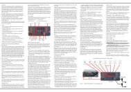
<strong>Speaker</strong> Connections<br />
Use this installation method if your receiver/<br />
processor has a dedicated LFE subwoofer output.<br />
Use the line-level input jack marked "SUB" for<br />
the Low-Frequency Effects channel. Connect this<br />
jack to the LFE output or subwoofer output<br />
on your receiver or amplifier. Connect each<br />
speaker to the corresponding speaker terminals<br />
on your receiver or amplifier.<br />
Make sure that you have configured your<br />
surround-sound processor for “Subwoofer On.”<br />
The left and right speakers should all be set to<br />
“Small.”<br />
F ro n t<br />
F ro n t<br />
Le f t<br />
Ri g h t<br />
– + – +<br />
F ron t<br />
L e f t<br />
SUB-TS Subwoofer<br />
SUB<br />
LINE LEVEL IN<br />
SUB /L F E<br />
O u t<br />
Rec eive r<br />
R<br />
L<br />
F ron t<br />
Ri gh t<br />
SPEAKER CONNECTIONS 9
<strong>Speaker</strong> Connections<br />
Use this installation method for Dolby Pro Logic<br />
or Dolby Virtual <strong>Speaker</strong> applications (not Dolby<br />
Digital, DTS ® or other digital processing), where<br />
the receiver/processor is equipped with a<br />
subwoofer output, or a volume-controlled<br />
preamp (line-) level output:<br />
Use RCA-type patch cords to connect the linelevel<br />
subwoofer output on your receiver or to<br />
amplifier either the left or right line-level input<br />
on the subwoofer.<br />
10 SPEAKER CONNECTIONS<br />
Use both the left and right inputs on the subwoofer<br />
if your receiver or processor has both left<br />
and right line-level outputs. In that case, you will<br />
need to supply a second interconnect cable.<br />
If your receiver is equipped with line-level outputs<br />
but does not have a separate subwoofer<br />
output, use a Y-adapter (not supplied) to bridge<br />
the receiver’s preamp output to the main amp<br />
input for that channel, and connect the long end<br />
of the adapter to the corresponding line-level<br />
input on the subwoofer.<br />
IMPORTANT: Do not use the Sub Input � on<br />
the subwoofer with Dolby Pro Logic processors.<br />
Front<br />
Left<br />
SUB-TS<br />
Subwoofer<br />
Line-Level<br />
R L<br />
SUB/LFE<br />
Out<br />
Receiver<br />
Front<br />
Right<br />
If your receiver/processor has a built-in lowpass-crossover<br />
filter for the subwoofer output,<br />
you may use the Sub Input � to bypass the<br />
subwoofer’s internal crossover.<br />
Connect each speaker to the corresponding<br />
speaker terminals on your receiver or amplifier.<br />
Make sure that you have configured your<br />
surround sound processor for “Subwoofer On.”<br />
The left and right speakers should all be set to<br />
“Small.”<br />
When all connections have been made, plug the<br />
AC power cord on the subwoofer into an AC<br />
outlet.<br />
Front<br />
Front<br />
Left<br />
Right<br />
– + – +
<strong>Speaker</strong> Connections<br />
Dolby* Pro Logic* (Non-Digital) –<br />
<strong>Speaker</strong> Level<br />
Use this installation method for Dolby Pro Logic<br />
or Dolby Virtual <strong>Speaker</strong> applications (not<br />
Dolby Digital, DTS ® or other digital processing),<br />
where the receiver/processor does not have a<br />
subwoofer output, or a volume-controlled<br />
preamp (line-) level output:<br />
Front<br />
Left<br />
Connect your receiver or amplifier’s front left<br />
and right speaker terminals to the left and right<br />
terminals on the subwoofer that are marked<br />
“High Level In.”<br />
Connect the left and right terminals on the subwoofer<br />
that are marked “High Level Out” to the<br />
corresponding terminals on the back of your<br />
front left and right speakers.<br />
– + – +<br />
H<br />
I<br />
G<br />
H<br />
L<br />
E<br />
V<br />
E<br />
L<br />
L<br />
R<br />
SUB-TS<br />
Subwoofer<br />
Receiver<br />
Front Left Front Right<br />
Front<br />
Right<br />
SPEAKER CONNECTIONS 11
Operation<br />
Move the Master Power switch (marked<br />
“Power” �) to the “ ” (On) position to use the<br />
subwoofer. The subwoofer will automatically<br />
turn itself on or go into standby mode<br />
depending on whether or not a signal is being<br />
sent to it by your receiver or surround processor,<br />
and provided that the Trigger On/Off Switch �<br />
is moved down so that it is in the "AUTO"<br />
position. When your receiver or amplifier is off,<br />
the subwoofer will be in standby mode and the<br />
LED Indicator on the top of the subwoofer will<br />
turn amber. When your receiver or amplifier is<br />
turned on, it will automatically turn itself on and<br />
the LED Indicator will turn blue.<br />
If you will be away from home for an extended<br />
period of time, or if the subwoofer will not be<br />
used, switch the Master Power switch � to<br />
the OFF position.<br />
12 OPERATION<br />
Volume<br />
Volume can be adjusted using the Subwoofer<br />
Level Control � (above), as shown below.<br />
Turn the control knob clockwise to increase the<br />
volume of the subwoofer, and counterclockwise<br />
to decrease the subwoofer's volume.<br />
Subwoofer<br />
Level<br />
MIN MAX<br />
Subwoofer<br />
Level<br />
MIN MAX<br />
Additional Bass Adjustments<br />
In addition to the volume adjustments described<br />
above, the subwoofer includes a Phase Switch<br />
� and a Filter Switch � that can be used to<br />
adjust the bass response to suit your listening<br />
environment or taste.<br />
In most situations, the Phase Switch � should<br />
be left in the NORMAL position.<br />
If you suspect that the subwoofer is playing out<br />
of phase with the other speakers, which would<br />
tend to diminish bass response, try placing this<br />
switch in the REVERSE position. There is no<br />
harm in experimenting, and you may return the<br />
switch to the NORMAL position at any time.<br />
If you rearrange your room and reposition the<br />
speakers, it would be a good idea to check<br />
whether they are in phase by flipping this<br />
switch.<br />
The High-Cut (Low-Pass) Filter Switch �<br />
limits the frequencies of the audio signal<br />
inputted to the subwoofer to the low frequencies<br />
that the subwoofer reproduces best.<br />
This allows the subwoofer to perform more<br />
efficiently, and with superior bass reproduction,<br />
minimizing distortion that might occur if the<br />
subwoofer attempted to reproduce higher<br />
frequencies. This switch should be left in the<br />
ON position, except:<br />
1. When the Sub Input � is being used, in<br />
which case it has no effect, or<br />
2. When the <strong>Speaker</strong>-Level Inputs � or the<br />
Line-Level Full-Range Inputs � are being<br />
used with a crossover or filter aboard the<br />
receiver or processor.<br />
In these two circumstances, place the switch in<br />
the OFF position.
Troubleshooting<br />
If there is no sound from Check that receiver/amplifier is on and a source is playing.<br />
any of the speakers: Check that the powered subwoofer is plugged in, its Power switch � is switched on to<br />
the “ON ” position.<br />
Check all wires and connections between receiver/amplifier and speakers. Make sure all wires<br />
are connected. Make sure none of the speaker wires are frayed, cut or punctured.<br />
Review proper operation of your receiver/amplifier.<br />
If there is no sound coming Check the “Balance” control on your receiver/amplifier.<br />
from one speaker: Check all wires and con nections between receiver/ amplifier and speakers. Make sure all wires are<br />
connected. Make sure none of the speaker wires are frayed, cut or punctured.<br />
In Dolby Digital or DTS ® modes, make sure that the receiver/processor is configured so that the<br />
speaker in question is enabled.<br />
If the system plays at low volumes Check all wires and con nec ti ons between receiver/amplifier and speakers.<br />
but shuts off as volume is Make sure all wires are connected.<br />
increased: Make sure none of the speaker wires are frayed, cut or punctured.<br />
If more than one pair of main speakers is being used, check the minimum impedance<br />
requirements of your receiver/amplifier.<br />
If there is low (or no) bass Make sure the connections to the left and right “<strong>Speaker</strong> Inputs” have the correct polarity (+ and –).<br />
output: Make sure the subwoofer is plugged into an active electrical outlet.<br />
Make sure the powered subwoofer is plugged in and switched on.<br />
In Dolby Digital or DTS ® modes, make sure your receiver/processor is<br />
configured so that the subwoofer and LFE output are enabled.<br />
TROUBLESHOOTING 13
Specifications<br />
<strong>HKTS</strong> 2<br />
<strong>System</strong><br />
Frequency Response<br />
35Hz – 20kHz (–6dB)<br />
SAT-TS<br />
Satellites<br />
Recommended Power<br />
10 – 120 Watts<br />
Impedance<br />
8 Ohms nominal<br />
Sensitivity<br />
86dB @ 1 Watt/1 meter<br />
Tweeter<br />
One 1/2" dome, video-shielded<br />
Midrange<br />
Dual 3" drivers, video-shielded<br />
Dimensions (H x W x D)<br />
243mm x 100mm x 92mm<br />
Weight<br />
1kg<br />
14 SPECIFICATIONS<br />
SUB-TS<br />
Subwoofer<br />
Amplifier<br />
200 Watts RMS<br />
Bass<br />
10" Woofer, bass-reflex enclosure<br />
Dimensions (H x W x D)<br />
479mm x 340mm x 340mm<br />
Weight<br />
15kg<br />
All features and specifications are subject to change without notice.<br />
<strong>Harman</strong> <strong>Kardon</strong> and Power for the Digital Revolution are registered trademarks<br />
of <strong>Harman</strong> International Industries, Incorporated.<br />
* Trademarks of Dolby Laboratories.<br />
DTS is a registered trademark of Digital <strong>Theater</strong> <strong>System</strong>s, Inc.
Important Safety Instructions<br />
1. Read these instructions.<br />
2. Keep these instructions.<br />
3. Heed all warnings.<br />
4. Follow all instructions.<br />
5. Do not use this apparatus near water.<br />
6. Clean only with a dry cloth.<br />
7. Do not block any ventilation openings. Install in accordance with the<br />
manufacturer’s instructions.<br />
8. Do not install near any heat sources such as radiators, heat registers, stoves or<br />
other apparatus (including amplifiers) that produce heat.<br />
9. Do not defeat the safety purpose of the polarized or grounding-type plug. A<br />
polarized plug has two blades with one wider than the other. A grounding-type plug<br />
has two blades and a third grounding prong. The wide blade or the third prong is<br />
provided for your safety. If the provided plug does not fit into your outlet, consult an<br />
electrician for replacement of the obsolete outlet.<br />
10. Protect the power cord from being walked on or pinched, particularly at plugs,<br />
convenience receptacles and the point where they exit from the apparatus.<br />
11. Only use attachments/accessories specified by the manufacturer.<br />
12. Use only with the cart, stand, tripod, bracket or table<br />
specified by the manufacturer or sold with the apparatus. When a<br />
cart is used, use caution when moving the cart/apparatus<br />
combination to avoid injury from tip-over.<br />
13. Unplug this apparatus during lightning storms or when unused for long periods<br />
of time.<br />
14. Refer all servicing to qualified service personnel. Servicing is required when the<br />
apparatus has been damaged in any way, such as power supply cord or plug is<br />
damaged, liquid has been spilled or objects have fallen into the apparatus, the<br />
apparatus has been exposed to rain or moisture, does not operate normally, or has<br />
been dropped.<br />
15. Do not expose this apparatus to dripping or splashing and ensure that no objects<br />
filled with liquids, such as vases, are placed on the apparatus.<br />
16. To completely disconnect this apparatus from the AC Mains, disconnect the<br />
power supply cord plug from the AC receptacle.<br />
17. The mains plug of the power supply cord shall remain readily operable.<br />
18. Do not expose batteries to excessive heat such assunshine, fire or the like.<br />
The lightning flash with arrowhead symbol, within an equilateral triangle,<br />
is intended to alert the user to the presence of uninsulated “dangerous<br />
voltage” within the product’s enclosure that may be of sufficient<br />
magnitude to constitute a risk of electric shock to persons.<br />
The exclamation point within an equilateral triangle is intended to alert<br />
the user to the presence of important operating and maintenance<br />
(servicing) instructions in the literature accompanying the product.<br />
WARNING: To reduce the risk of fire or electric shock, do not expose this apparatus to<br />
rain or moisture.<br />
15
250 Crossways Park Drive, Woodbury, New York 11797<br />
www.harmankardon.com<br />
<strong>Harman</strong> Consumer Group International:<br />
2, Route de Tours, 72500 Château-du-Loir, France<br />
© 2009 <strong>Harman</strong> <strong>Kardon</strong>, Incorporated<br />
Part 406-000-05513-E