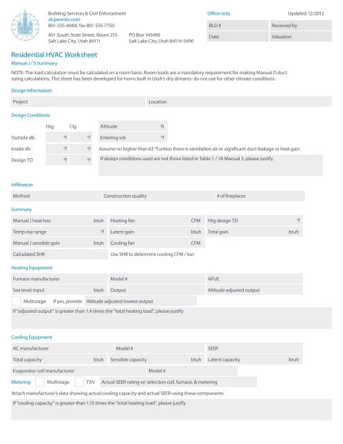
Residential HVAC Worksheet
Residential HVAC Worksheet
Residential HVAC Worksheet

You also want an ePaper? Increase the reach of your titles
YUMPU automatically turns print PDFs into web optimized ePapers that Google loves.
Building Services & Civil Enforcement<br />
slcpermits.com<br />
801-535-6000, fax 801-535-7750<br />
451 South State Street, Room 215 PO Box 145490<br />
Salt Lake City, Utah 84111 Salt Lake City, Utah 84114-5490<br />
Office only Updated 12/2012<br />
BLD #<br />
Received by<br />
Date<br />
Valuation<br />
<strong>Residential</strong> <strong>HVAC</strong> <strong>Worksheet</strong><br />
Manual J / S Summary<br />
NOTE: The load calculation must be calculated on a room basis. Room loads are a mandatory requirement for making Manual D duct<br />
sizing calculations. This sheet has been developed for homs built in Utah’s dry dimares- do not use for other climate conditions.<br />
Design Information<br />
Project<br />
Location<br />
Design Conditions<br />
Htg Clg<br />
Altitude ft<br />
Outside db<br />
°f<br />
°f<br />
Entering wb °f<br />
Inside db<br />
Design TD<br />
°f °f<br />
°f °f<br />
Assume no higher than 63 °f unless there is ventilation air or significant duct leakage or heat gain<br />
If design conditions used are not those listed in Table 1 / 1A Manual 3, please justify.<br />
Infiltration<br />
Method Construction quality # of fireplaces<br />
Summary<br />
Manual J heat loss<br />
btuh<br />
Heating fan<br />
CFM<br />
Htg design TD °f<br />
Temp rise range to °f<br />
Latent gain<br />
btuh<br />
Total gain<br />
btuh<br />
Manual J sensible gain<br />
btuh<br />
Cooling fan<br />
CFM<br />
Calculated SHR<br />
Use SHR to determine cooling CFM / ton<br />
Heating Equipment<br />
Furnace manufacturer<br />
Model #<br />
AFUE<br />
Sea level: input<br />
btuh<br />
Output<br />
Altitude adjusted output<br />
Multistage If yes, provide Altitude adjusted lowest output<br />
If “adjusted output” is greater than 1.4 times the “total heating load”, please justify<br />
Cooling Equipment<br />
AC manufacturer<br />
Model #<br />
SEER<br />
Total capacity<br />
btuh<br />
Sensible capacity btuh Latent capacity btuh<br />
Evaporator coil manufacturer Model #<br />
Metering<br />
Multistage<br />
TXV<br />
Actual SEER rating w/ selection coil, furnace, & metering<br />
Attach manufacturer’s data showing actual cooling capacity and actual SEER using these components<br />
If “cooling capacity” is greater than 1.15 times the “total heating load”, please justify
Manual J / S Summary<br />
Instructions<br />
The load information asked for on the<br />
summary must be taken from the actual<br />
load calculation completed on the project.<br />
Project<br />
Identify project name, lot number- information<br />
that matches the plan submitted.<br />
Location<br />
The city or town must be reasonably close<br />
to actual location. Software used may not<br />
have the specific location in the database.<br />
Outside Dry Bulb, Inside Dry Bulb<br />
Temperature data should be from Table 1 or<br />
Table 1A of ACCA Manual J. It is understood<br />
that there may be situations where a slight<br />
adjustment to this values is necessary. For<br />
example; there may be areas in the Salt<br />
Lake Valley where the low temperature is<br />
historically lower than the airport temperature.<br />
If values are adjusted- please justify the<br />
adjustment. Provide both heating (htg) and<br />
cooling (clg) design temperatures. If inside<br />
or outside design conditions listed are not<br />
the same values listed in Manual J, explain<br />
why the different values were used.<br />
Entering WB<br />
The entering wet-bulb represents the<br />
default value wet-bulb temperature across<br />
the evaporator coil. This will typically be<br />
63 °f (75 °f dry bulb) relative humidity). A<br />
higher wb temperature will result from duct<br />
leakage, un-insulated duct or ventilation<br />
air- any condition that raises the return<br />
air temperature. Use this wb temperature<br />
when selecting cooling condenser from<br />
manufacturer’s comprehensive data.<br />
Design TD<br />
TD: the temperature difference between<br />
inside and outside design temperatures.<br />
Infiltration<br />
Infiltration calculations are based on the<br />
Construction Quality. Version 7 of Manual ] uses<br />
Best, Average or Poor to evaluate Infiltration.<br />
Version 8AE uses Tight, Semi-Tight, Average,<br />
Semi-Loose and Loose to evaluate. Version 8<br />
goes into very specific detail for a more accurate<br />
number. Note method used on summary. Open<br />
firebox fireplaces that draw air from inside the<br />
home must be included, even if there is a 4”<br />
‘combustion air’ flex bring air into the fireplace.<br />
Sealed, direct vent type fireplaces should<br />
not be counted. Methods include: Simplified<br />
/ Default Method- taken from Table 5A;<br />
Component Leakage Area Method- calculating<br />
infiltration based on individual leakage points<br />
taken from Table 5C of Manual J8; or Blower<br />
Door Method, where the actual leakage is<br />
based on a blower door test on the home.<br />
Manual J Heat Loss<br />
This is the whole house winter heat loss taken<br />
directly from the completed attached Load<br />
Calculation. Load must account for all factors<br />
such as loss building components as well as loss<br />
through infiltration, ventilation, and duct losses.<br />
Heating Fan<br />
Heating airflow typically may be lower than<br />
cooling cfm. Adjusted to insure the temperature<br />
rise across the heat exchanger falls within the<br />
range specified by the manufacturer. Software<br />
will often do this calculation and provide a<br />
correct heating cfm. See Manual S Section 2-6 -<br />
Rise (°f) = Output Capacity ÷ (1.1 x heating cfm)<br />
Manufacturer’s Temperature Rise Range<br />
Range taken from manufacturer’s<br />
performance data. Various manufacturers<br />
may certify ranges from 20 - 70 °f.<br />
Manual J — Sensible Gain<br />
The whole house summer heat gain taken<br />
directly from the completed attached Load<br />
Calculation. Load must account for all factors<br />
including gain through building components,<br />
solar gain, infiltration, ventilation and<br />
ducts. Also includes the sensible internal<br />
gains from appliances and people.<br />
Manual 3 — Latent Gain<br />
The gains due to moisture in the air. Large latent<br />
load are typically from moisture migration<br />
into the home from outside in humid climates.<br />
People, cooking, plants, bathing and laundry<br />
washing can all add to the latent load in a home.<br />
Total Gain<br />
The combined total of the sensible and latent<br />
gain. May be referred to as Total Cooling Load.<br />
SHR- Sensible Heat Ratio<br />
Use to determine Cooling cfm per ton.<br />
The ratio of sensible heat gain to total heat<br />
gain. SHR = Sensible Heat Gain ÷ Total<br />
Heat Gain. Recommended air flows: If SHR<br />
is below 0.80 select 350 cfm / ton; if SHR<br />
is between 0.80 & 0.85 select 400 cfm; if<br />
SHR is greater than 0.85, select 450 cfm<br />
/ ton. Note: This cfm is not the final cfm;<br />
additional adjustment may be required for<br />
Altitude. See next item- Cooling Fan.<br />
Cooling Fan<br />
Software used to perform the calculation<br />
will typically provide a minimum cfm<br />
based on the minimum required size of the<br />
equipment. This number may be adjusted<br />
to meet specific requirements of the home.<br />
Heating and Cooling CFM may or may not<br />
be the same. The cooling CFM should be<br />
around 450 CFM per ton of cooling in Utah’s<br />
dry climates. For higher altitudes, CFM must<br />
be adjust up as detailed in ACCA / ANSI<br />
Manual S. Mountain location should expect<br />
Cooling CFM at 500 CFM per ton and higher.<br />
HEATING<br />
Equipment<br />
List specific equipment to be used. This<br />
information is not required on the Load<br />
Calculation documents, however it must<br />
be provided here to verify equipment<br />
sizing against calculated loads.<br />
AFUE<br />
The AFUE (Annual Fuel Utilization Efficiency)<br />
listed here will be compared to that listed on<br />
plans and on energy compliance documents<br />
(RES check or other). It must also match the<br />
equipment actually installed in the home.<br />
Sea Level Input<br />
The listed input on the furnace label<br />
and in manufacturers’ documentation.<br />
Input represents the total amount<br />
of heat in the gas at sea level.<br />
Output<br />
The amount a heat available for discharge<br />
into the conditioned space. The input less any<br />
vent or stack losses, or heat that is carried out<br />
with the products of combustion. May be take<br />
from manufacturer’s performance data or<br />
calculated using input and furnace efficiency.<br />
Altitude Adjusted Output<br />
This number is the actual output that will be<br />
attained after the furnace has been adjusted<br />
for efficiency and de-rated for altitude (typically<br />
4% for every 1000’ above sea-level, however<br />
2% /1000’ for many 90+ efficient furnaces).<br />
Some manufacturers may have different<br />
requirements- adjustments should be made<br />
per their requirements. Calculations should be<br />
attached. Example: 80,000 input 91% efficient<br />
furnace in Salt Lake, with manufacturers’<br />
installation instructions specifying 4% /<br />
1000’. 80,000 x .91 x .83 = 60,424 btuh.<br />
Multi-Stage Furnace<br />
Multi-stage and modulating equipment is now<br />
available. When comparing to heating load<br />
calculated, use the maximum adjusted output<br />
to verify the furnace is large enough and the<br />
lowest output to insure it is not too large.<br />
Size Justification<br />
Example: If the Total Heating Load = 29954<br />
btuh. A furnace with an adjusted output larger<br />
than 45,000 btuh (29954 x 1.5 = 44931) would<br />
require an explanation justifying the size.<br />
COOLING<br />
Equipment<br />
List specific equipment to be used. Provide<br />
manufacturers comprehensive data for<br />
furnace, furnace blower and condenser, with<br />
capacities at design conditions highlighted.<br />
Condenser SEER<br />
This SEER (Seasonal Energy Efficiency Ratio) is<br />
the listed SEER for this model series, not the<br />
exact SEER with components used this system.
Total Capacity<br />
Manufacturers base data is based on ARI<br />
Standard 210 / 240 ratings; 95 °f outdoor air<br />
temperature, 80 °f db / 67 °f wb entering<br />
evaporator. As the Design Conditions<br />
are different than this standard, refer<br />
to manufacturers expanded ratings for<br />
capacities at actual design conditions.<br />
Total capacity is the latent and sensible<br />
capacity at design conditions<br />
Sensible Capacity<br />
The sensible only capacity from<br />
the manufacturer’s expanded<br />
data at design conditions.<br />
Latent Capacity<br />
The latent only capacity from the<br />
manufacturer’s expanded data at design<br />
conditions. NOTE: One half of the excess latent<br />
capacity may be added to the sensible capacity.<br />
Evaporator Coil Make and Model #<br />
List the exact model number for the<br />
evaporator coil used this system. If coil is<br />
from a different manufacturer than the<br />
condenser is used, provide data from both<br />
manufacturers verifying actual performance.<br />
Expansion / Metering<br />
Provide the specific metering usedorifice<br />
or TXV (thermostat expansion<br />
valve). If the manufacturer has several<br />
options, list the option used.<br />
Actual SEER Rating<br />
Attach manufacturers’ documentation or ARI<br />
report showing actual cooling capacity, and<br />
actual SEER using the components used this<br />
system. Indoor air handler / furnace blower<br />
must be included in this documentation. Do<br />
not use ARI (ARHI) data for actual sizing.<br />
Size Justification<br />
If cooling capacity is 15% greater than<br />
the calculated Cooling load explain. High<br />
latent (moisture) loads can be listed here.<br />
Special requirements particular to the<br />
customer may also be noted here.<br />
Manual D Calculations & Summary<br />
Project<br />
Friction Rate <strong>Worksheet</strong> & Steps<br />
1 Manufacturer’s Blower Data<br />
External static pressure (ESP)<br />
IWC<br />
CFM<br />
2 Device Pressure Losses<br />
Evaporator<br />
Supply register .03<br />
Other device<br />
Air filter<br />
Return grill .03<br />
Total device losses (DPL)<br />
IWC<br />
3 Available Static Pressure (ASP)<br />
ASP = ( ESP - DPL )<br />
IWC<br />
4 Total Effective Length (TEL)<br />
Supply side TEL<br />
ft Return side TEL<br />
ft<br />
Total effective length (TEL) = supply side TEL + return side TEL<br />
5 Friction Rate Design Value (FR)<br />
FR = ( ( 100 x ASP ) / TEL ) IWX / 100’<br />
ft<br />
This friction rate (FR) calculated in Step 5 is<br />
the rate to be used with a duct calculator or a<br />
friction chart for the duct design on this project.<br />
Attach at a minimum, a one line<br />
diagram showing the duct system<br />
with fittings, sizes, equivalent lengths<br />
through fitting and duct lengths.<br />
Mechanical Sizing<br />
Name of contractor / designer<br />
Phone<br />
Fax<br />
Address<br />
Permit #<br />
Lot #<br />
Vent height (base of duct to roof exit)<br />
ft
Boiler or furnace input rating<br />
btu<br />
Boiler or furnace #2 input rating<br />
btu<br />
De-rated input rating (use .83)<br />
btu<br />
De-rated input rating (use .83)<br />
btu<br />
Connector rise<br />
ft<br />
Connector rise<br />
ft<br />
Connector run<br />
ft<br />
Connector run<br />
ft<br />
Connector size<br />
in<br />
Connector size<br />
in<br />
Orifice size<br />
in<br />
Orifice size<br />
in<br />
Water heater input rating<br />
btu<br />
Water heater #2 input rating<br />
btu<br />
De-rated input rating (.83 minimum)<br />
btu<br />
De-rated input rating (.83 minimum)<br />
btu<br />
Connector rise<br />
ft<br />
Connector rise<br />
ft<br />
Connector run<br />
ft<br />
Connector run<br />
ft<br />
Connector size<br />
in<br />
Connector size<br />
in<br />
Orifice size<br />
in<br />
Orifice size<br />
in<br />
Total heat input of all appliances<br />
Vent size for the system<br />
Combustion air size<br />
Signature<br />
btu<br />
in<br />
in²<br />
Attach a complete gas pipe layout & sizing detail to the plan or permit application.<br />
If a manifold is used to connect the appliances on the<br />
horizontal, it shall be the same size as the vent.<br />
To the best of my knowledge, I certify that the information contained<br />
within this document is true, correct, and meets the requirements of the<br />
2009 International Mechanical Code and International Fuel Gas Code.<br />
Date<br />
Mechanical Sizing <strong>Worksheet</strong><br />
How-To<br />
Materials needed to fill out this form are the<br />
International fuel gas Code and the Questar<br />
Recommended Good Practices Book.<br />
VENT SIZING<br />
1 Vent height is measured from the<br />
draft diverter or appliance vent<br />
outlet to the top of the vent cap.<br />
2 Connector rise is the height of the vent<br />
connector from the appliance outlet<br />
to the center of the tee in the vent at<br />
the point of connection to the vent.<br />
3 Connector run is the horizontal distance<br />
from the appliance vent outlet to the vent.<br />
4 Go to the International Fuel Gas<br />
Code Chapter 5. Sizing is done to<br />
the appropriate gamma table .<br />
5 The gamma tables are in Btu and not ft³<br />
DE-RATING<br />
1 See Questar handbook for a step-by-step<br />
formula and the required conversion<br />
numbers. To complete this form:<br />
a Input is de-rated at 4% per<br />
1000’ in elevation.<br />
b Example: SLC has a 17% de-ration<br />
factor. On a 100,000 Btu furnace you<br />
multiply 100,000 x .83 = 83,000 Btu’s<br />
c<br />
On the vent sizing this becomes<br />
the fan min. The fan max is the<br />
listed input rate example fan<br />
min = 83 and fan max = 100<br />
d The Btu to ft³ conversion number for<br />
SLC is 890 and the specific gravity of<br />
the gas is .60. Divide the new input<br />
rating by 890, 83,000 = 93.258 ft³. 890<br />
e Take the ft³ of input and divide it by the<br />
number of burners on the appliance,<br />
this will give you the ft³ / burner. Then<br />
use the orifice tables in the Questar<br />
handbook to determine the orifice size.<br />
Example if you have 4 burners: 93.258<br />
ft³ / 4 burners = 23.315 ft³ / 1 burner.<br />
Match as close as possible to the<br />
Orifice table in the handbook. In this<br />
sample the orifice size would be (49)<br />
2 Use the International Fuel Gas Code and the<br />
International Mechanical Code to complete<br />
the vent sizing and the combustion air<br />
sizing. See Chapter 5 IFC for the rules and<br />
the tables to fill out this portion of the form.<br />
ICBO also has available a commentary on<br />
the mechanical code that contains a stepby-step<br />
examples of how to size the vents.<br />
3 The International Mechanical Code<br />
commentary also contains examples to<br />
size the gas pipe. You must show the pipe<br />
lengths, the Btus and the volume of each<br />
appliance and show the size of each length<br />
of pipe. All tables necessary to size gas pipe<br />
are also contained in the International Fuel<br />
Gas Code, and in the Questar handbook.<br />
4 For Salt Lake City use:<br />
a 890 Btu per ft³<br />
b A multiplier of .83<br />
c Specific gravity of .60<br />
d Combustion air is computed at 1<br />
in² per 3,000 Btu of input of all fuel<br />
burning appliances in the room.<br />
One duct upper 12” of the room.<br />
E Questar gas has a training program<br />
available to all persons and contractors.