Abaqus Technology Brief Automotive Brake Squeal Analysis Using ...
Abaqus Technology Brief Automotive Brake Squeal Analysis Using ...
Abaqus Technology Brief Automotive Brake Squeal Analysis Using ...

Create successful ePaper yourself
Turn your PDF publications into a flip-book with our unique Google optimized e-Paper software.
<strong>Abaqus</strong> <strong>Technology</strong> <strong>Brief</strong><br />
TB-05-BRAKE-1<br />
Revised: April 2007<br />
.<br />
<strong>Automotive</strong> <strong>Brake</strong> <strong>Squeal</strong> <strong>Analysis</strong> <strong>Using</strong> a Complex Modes Approach<br />
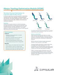
Summary<br />
A methodology to study friction-induced squeal in a complete<br />
automotive disc brake assembly is presented. The<br />
analysis process uses a nonlinear static simulation sequence<br />
followed by a complex eigenvalue extraction to<br />
determine the dynamic instabilities that are manifested as<br />
unwanted noise. The effects of assembly loads; nonuniform<br />
contact pressure between the brake linings and disc;<br />
velocity-, temperature-, and pressure-dependent friction<br />
coefficients; friction-induced damping; and lining wear can<br />
be included. The methodology is demonstrated with a<br />
representative disc brake assembly. Good correlation between<br />
the analysis results and available experimental<br />
data is achieved.<br />
Background<br />
The operating principle of an automobile disc brake system<br />
is to slow a moving vehicle by pressing brake pads<br />
against rotating wheel discs. The friction between the pad<br />
linings and the disc dissipates the energy of the moving<br />
vehicle, resulting in deceleration.<br />
During brake operation, the friction between the lining and<br />
the disc can induce a dynamic instability in the system.<br />
This instability can create noise, commonly known as<br />
brake squeal. One possible explanation for the brake<br />
squeal phenomenon is the coupling of two neighboring<br />
vibration modes. If two modes are close to each other in<br />
the frequency range and have similar characteristics, they<br />
may merge if the coefficient of friction between the pad<br />
and disc increases. When these modes merge at the<br />
same frequency (become coupled), one of them becomes<br />
unstable. The unstable mode can be identified during<br />
complex eigenvalue extraction because the real part of<br />
the eigenvalue corresponding to an unstable mode is<br />
positive. The instability in the brake system design can be<br />
eliminated by changing the geometry or material properties<br />
of the brake components to decouple the modes.<br />
As vehicle quality improves, customers demand quieter<br />
brakes. Customer complaints result in significant warranty<br />
costs yearly, motivating the need to study brake squeal<br />
early in the design process. The complex modes approach<br />
is a common finite element modeling technique<br />
used to simulate this phenomenon (e.g., Ref. 1–11).<br />
<strong>Abaqus</strong> affords a straightforward brake squeal analysis<br />
methodology. The process consists of preloading the<br />
brake, rotating the disc, extracting natural frequencies,<br />
and computing complex eigenvalues. The approach combines<br />
all steps in one analysis and accounts for friction<br />
Key <strong>Abaqus</strong> Features and Benefits<br />
• Ability to use a single model for the entire<br />
analysis sequence<br />
• The inclusion of nonlinear effects in the extraction<br />
of the complex eigenmodes<br />
• Ability to model each part of the brake assembly<br />
independently, without the need for matching<br />
meshes<br />
coupling and nonlinear effects without the need for matrix<br />
input methods or matching meshes.<br />
The purpose of the analysis presented here is to demonstrate<br />
the methodology by identifying any potentially unstable<br />
modes in a particular disc brake system.<br />
Finite Element <strong>Analysis</strong> Approach<br />
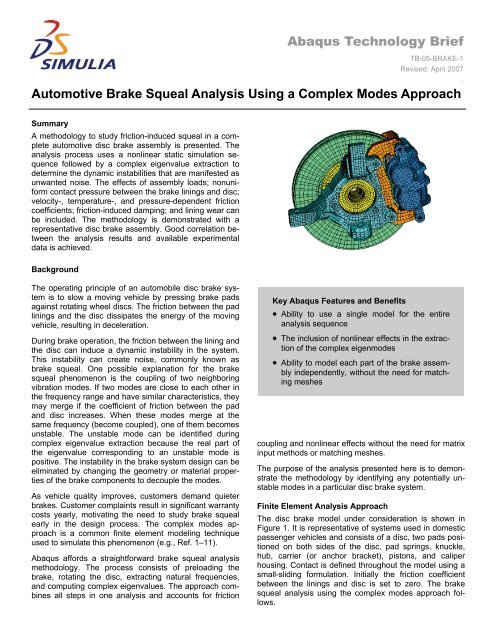
The disc brake model under consideration is shown in<br />
Figure 1. It is representative of systems used in domestic<br />
passenger vehicles and consists of a disc, two pads positioned<br />
on both sides of the disc, pad springs, knuckle,<br />
hub, carrier (or anchor bracket), pistons, and caliper<br />
housing. Contact is defined throughout the model using a<br />
small-sliding formulation. Initially the friction coefficient<br />
between the linings and disc is set to zero. The brake<br />
squeal analysis using the complex modes approach follows.
2<br />
Figure 1: Disc brake model.<br />
Step 1: Bolt pre-tension and spring interference fit<br />
analysis<br />
In the first analysis step the model is brought into its assembled<br />
state. Fastening forces are introduced in all the<br />
bolts, and a shrink-fit procedure is used to determine the<br />
assembled state of the springs that secure the brake pads<br />
in the assembly. Figure 2 displays a close-up view of a<br />
pad retention spring after the shrink-fit procedure.<br />
Figure 3: Caliper and piston, with<br />
pressure-loaded surfaces highlighted.<br />
The friction coefficient is ramped up from zero to the desired<br />
value to avoid the discontinuities and convergence<br />
problems that may arise because of the change in the<br />
friction coefficient that typically occurs when bodies in<br />
contact are moving with respect to each other.<br />
At the end of this step a steady-state braking condition is<br />
obtained. A matched mesh between the disc and the pad<br />
is not required, and a fine mesh is not required for the<br />
whole disc; rather, it is needed only in the region where<br />
the pad makes contact (see Figure 4).<br />
Figure 2: Shrink-fit of a brake pad spring.<br />
Step 2: Establish disc/brake pad contact<br />
Figure 3 displays the caliper housing and a piston. In Step<br />
2 pressure is applied on the pistons and housing in a<br />
static analysis. The contact between the pad lining and<br />
the disc is, thus, established. Step 2 allows the contact<br />
pressure distribution on the lining surface to be determined<br />
when the disc is not rotating.<br />
Step 3: Establish steady-state rotational motion<br />
In this static step a rotational velocity is imposed on the<br />
disc as a predefined field variable. This provides for the<br />
modeling of steady-state frictional sliding between two<br />
bodies that are moving with different velocities. The imposed<br />
velocity of 9.26 rad/s corresponds to braking at low<br />
velocity. In addition, the friction coefficient μ is increased<br />
to 0.4 from 0.0. The present analysis uses a constant<br />
value of μ. In general, however, the friction coefficient can<br />
be defined as a function of the relative velocity (slip rate),<br />
contact pressure, and temperature. If the friction coefficient<br />
depends on the slip rate, the rotational velocity imposed is<br />
used to determine the corresponding value of μ.<br />
Figure 4: Disc mesh, showing refinement<br />
under pad contact area.<br />
Step 4: Extraction of real eigenvalues and mode<br />
shapes<br />
The preceding steps determine the initial stresses in the<br />
model and the steady-state braking conditions. In Step 4<br />
the real eigenvalues and mode shapes of the model are<br />
extracted. In this procedure the tangential degrees of freedom<br />
at the contact nodes, at which a velocity differential is<br />
defined, are not constrained. The set of eigenmodes provides<br />
the subspace for computing complex eigenvalues in<br />
the next step.
3<br />
Step 5: Extraction of complex eigenvalues and mode<br />
shapes<br />
The complex modes analysis determines the complex<br />
eigenvalues based on the real frequency spectrum calculated<br />
in Step 4. The complex modes analysis is performed<br />
up to 10 kHz. Although not considered in the present<br />
analysis, this procedure can account for friction-induced<br />
damping.<br />
Results<br />
Some representative results from each analysis step follow.<br />
Figure 5 shows the Mises stress distribution on the<br />
surface of the disc due to the bolt fastening simulated in<br />
Step 1. The axial force of the bolts is specified as 2 kN,<br />
and all bolts are tightened simultaneously.<br />
Figure 6b: Contact pressure distribution on the inboard<br />
lining at the end of Step 2.<br />
The surface pressure distribution on the brake linings after<br />
the application of pressure in Step 2 is shown in Figure<br />
6a and Figure 6b. The accuracy of the complex mode<br />
calculation depends strongly on the accuracy of the surface<br />
pressure distribution between the pad and the disc.<br />
After the rotational velocity is applied to the disc and the<br />
friction coefficient between the disc and the linings is increased<br />
in Step 3, the surface pressure distribution on the<br />
linings changes to that shown in Figure 7a and Figure 7b.<br />
Figure 7a: Contact pressure distribution<br />
on the outboard lining at the end of Step 3.<br />
Figure 5: Mises stress distribution<br />
in the disc after bolt tightening.<br />
Figure 7b: Contact pressure distribution<br />
on the inboard lining at the end of Step 3.<br />
When the real part of a complex eigenvalue becomes<br />
positive for a given set of operational parameters, the corresponding<br />
mode becomes unstable and has the potential<br />
to radiate squeal noise. An unstable mode is, thus, referred<br />
to as a squeal mode.<br />
Figure 6a: Contact pressure distribution on the<br />
outboard lining at the end of Step 2.<br />
The disc brake system being modeled has been tested<br />
experimentally. The effects of two parameters, the caliper<br />
pressure and the friction coefficient, on the unstable<br />
modes were studied.
4<br />
Figure 8 displays the real parts of the complex eigenvalues<br />
determined when the coefficient of friction is set to<br />
0.4 and the caliper pressure is set to 1.5 MPa.<br />
Two frequency bands, corresponding to the experimentally<br />
observed squeal frequencies, are also included in the<br />
figure.<br />
It is clear from Figure 8 that the predicted squeal modes<br />
are included in those observed in the experiment.<br />
As part of an experimental study presented in Abendroth<br />
et al. (Ref. 12), an electronic speckle pattern interferometry<br />
technique is used to measure the deflected shapes of<br />
a disc brake system. The system of Abendroth et al.<br />
(Ref. 12) differs slightly from that currently being simulated<br />
but still allows for meaningful comparisons.<br />
As displayed in Figure 9, the experimentally measured<br />
shapes and the predicted shapes for the low frequency<br />
squeal mode show similarity. This mode is associated<br />
with out-of-plane disc motion coupled with pad modes.<br />
The high frequency squeal mode is dominated by tangential<br />
motion (Figure 10, next page) in which the disc exhibits<br />
predominantly in-plane rotational action.<br />
It is natural to assume that the modes with the largest real<br />
part of an eigenvalue are likely to be unstable. However,<br />
sometimes such modes are over predictions and unstable<br />
modes with lower values of the real part can be the actual<br />
squeal modes. A preferred approach to calibrating analytical<br />
models is to start with the experimental data, identify<br />
an unstable mode of interest, and look for it among predicted<br />
instabilities.<br />
Although not considered in the present analysis, Bajer et<br />
al. (Ref. 11) reviewed the effects of lining wear on the<br />
brake squeal predictions. The wearing effect causes the<br />
nodes at the contact surface to move by just a small<br />
amount, but the difference in the contact pressure distribution<br />
on the linings is very significant. The improved contact<br />
pressure prediction results in improved squeal mode<br />
correlation with the experimental data.<br />
450<br />
400<br />
350<br />
300<br />
Experimental ranges<br />
Friction=0.4<br />
Real<br />
250<br />
200<br />
150<br />
100<br />
50<br />
0<br />
1000 2000 3000 4000 5000 6000 7000 8000 9000 10000<br />
Frequency<br />
Figure 8: The predicted squeal modes at 2.2 kHz and 6.9 kHz lie in the bands<br />
(2.2–2.4 kHz and 6.6–7.0 kHz) observed experimentally.<br />
<strong>Brake</strong> disc vibration at 2.1 kHz and 18 rpm using electronic speckle<br />
pattern interferometry<br />
Figure 9: Mode shapes of the unstable mode at 2.2 kHz. The snapshot from the<br />
test (left) shows the mode shape when the squeal noise occurs.
5<br />
Figure 10: Mode shape of the unstable modes at 2.2 kHz (left) and 6.9 kHz (right). The high<br />
frequency contour is in a cylindrical coordinate system and shows circumferential displacement magnitude<br />
Acknowledgements<br />
The authors would like to thank the MANDO Corporation and SIMULIA Korea for providing the materials discussed in<br />
this article.<br />
References<br />
1. Liles, G. D., “<strong>Analysis</strong> of Disc <strong>Brake</strong> <strong>Squeal</strong> <strong>Using</strong> Finite Element Methods,” SAE Paper 891150.<br />
2. Nack, W. V., and A. M. Joshi, “Friction Induced Vibration: <strong>Brake</strong> Moan,” SAE Paper 951095.<br />
3. Hamzeh, O. N., W. Tworzydlo, H. J. Chang, and S. Fryska, “<strong>Analysis</strong> of Friction-Induced Instabilities in a Simplified<br />
Aircraft <strong>Brake</strong>,” SAE <strong>Brake</strong> Colloquium, 1999.<br />
4. Kung, S.-W., K. B. Dunlap, and R. S. Ballinger, “Complex Eigenvalue <strong>Analysis</strong> for Reducing Low Frequency<br />
<strong>Squeal</strong>,” SAE Paper 2000-01-0444.<br />
5. Moirot, F. C., A. Nehme, and Q. C. Nguyen, “Numerical Simulation to Detect Low-Frequency <strong>Squeal</strong> Propensity,”<br />
SAE Paper 2000-01-2767.<br />
6. Shi, T. S., O. Dessouki, T. Warzecha, W. K. Chang, and A. Jayasundera, “Advances in Complex Eigenvalue<br />
<strong>Analysis</strong> for <strong>Brake</strong> Noise,” SAE Paper 2001-01-1603.<br />
7. Lee, L., K. Xu, B. Malott, M. Matsuzaki, and G. Lou, “A Systematic Approach to <strong>Brake</strong> <strong>Squeal</strong> Simulation <strong>Using</strong><br />
MacNeal Method,” SAE Paper 2002-01-2610.<br />
8. Ouyang, H.-J., W. V. Nack, Y. Yuan, and F. Chen, “On <strong>Automotive</strong> Disc <strong>Brake</strong> <strong>Squeal</strong>-Part II: Simulation and<br />
<strong>Analysis</strong>,” SAE Paper 2003-01-0684.<br />
9. Bajer, A., V. Belsky, and L.-J. Zeng, “Combining a Nonlinear Static <strong>Analysis</strong> and Complex Eigenvalue Extraction<br />
in <strong>Brake</strong> <strong>Squeal</strong> Simulation,” SAE Paper 2003-01-3349.<br />
10. Kung, S.-W., G. Stelzer, V. Belsky, and A. Bajer, “<strong>Brake</strong> <strong>Squeal</strong> <strong>Analysis</strong> Incorporating Contact Conditions and<br />
Other Nonlinear Effects,” SAE Paper 2003-01-3343.<br />
11. Bajer, A., V. Belsky, and S.-W. Kung, “The Influence of Friction-Induced Damping and Nonlinear Effects on<br />
<strong>Brake</strong> <strong>Squeal</strong> <strong>Analysis</strong>,” SAE Paper 2004-01-2794.<br />
12. Abendroth, H., “Advances in <strong>Brake</strong> NVH Test Equipment,” <strong>Automotive</strong> Engineering International, pp. 60, February<br />
1999.
6<br />
<strong>Abaqus</strong> References<br />
For additional information on the <strong>Abaqus</strong> capabilities referred to in this brief, see the following <strong>Abaqus</strong> Version 6.7<br />
documentation references:<br />
• <strong>Analysis</strong> User’s Manual<br />
– “Static stress analysis,” Section 6.2.2<br />
– “Natural frequency extraction,” Section 6.3.5<br />
– “Complex eigenvalue extraction,” Section 6.3.6<br />
• Example Problems Manual<br />
– “<strong>Brake</strong> squeal analysis,” Section 2.2.5<br />
About SIMULIA<br />
SIMULIA is the Dassault Systèmes brand that delivers a scalable portfolio of Realistic Simulation solutions including the <strong>Abaqus</strong> product<br />
suite for Unified Finite Element <strong>Analysis</strong>, multiphysics solutions for insight into challenging engineering problems, and lifecycle<br />
management solutions for managing simulation data, processes, and intellectual property. By building on established technology, respected<br />
quality, and superior customer service, SIMULIA makes realistic simulation an integral business practice that improves product<br />
performance, reduces physical prototypes, and drives innovation. Headquartered in Providence, RI, USA, with R&D centers in<br />
Providence and in Suresnes, France, SIMULIA provides sales, services, and support through a global network of over 30 regional<br />
offices and distributors. For more information, visit www.simulia.com<br />
The 3DS logo, SIMULIA, <strong>Abaqus</strong>, and the <strong>Abaqus</strong> logo are trademarks or registered trademarks of Dassault Systèmes or its subsidiaries, which include ABAQUS, Inc. Other company, product, and<br />
service names may be trademarks or service marks of others.<br />
Copyright © 2007 Dassault Systèmes