Wave reflection and transmission in composite beams containing ...
Wave reflection and transmission in composite beams containing ...
Wave reflection and transmission in composite beams containing ...

Create successful ePaper yourself
Turn your PDF publications into a flip-book with our unique Google optimized e-Paper software.
ARTICLE IN PRESS<br />
Journal of Sound <strong>and</strong> Vibration 313 (2008) 676–695<br />
JOURNAL OF<br />
SOUND AND<br />
VIBRATION<br />
www.elsevier.com/locate/jsvi<br />
<strong>Wave</strong> <strong>reflection</strong> <strong>and</strong> <strong>transmission</strong> <strong>in</strong> <strong>composite</strong> <strong>beams</strong><br />
conta<strong>in</strong><strong>in</strong>g semi-<strong>in</strong>f<strong>in</strong>ite delam<strong>in</strong>ation<br />
Wan-Chun Yuan a , Li Zhou a , Fuh-Gwo Yuan b,<br />
a College of Aerospace Eng<strong>in</strong>eer<strong>in</strong>g, Nanj<strong>in</strong>g University of Aeronautics & Astronautics, Nanj<strong>in</strong>g 210016, Ch<strong>in</strong>a<br />
b Department of Mechanical <strong>and</strong> Aerospace Eng<strong>in</strong>eer<strong>in</strong>g, North Carol<strong>in</strong>a State University, Raleigh, NC 27695-7921, USA<br />
Received 26 January 2007; received <strong>in</strong> revised form 18 November 2007; accepted 3 December 2007<br />
H<strong>and</strong>l<strong>in</strong>g Editor: P. Davies<br />
Available onl<strong>in</strong>e 8 February 2008<br />
Abstract<br />
<strong>Wave</strong> <strong>reflection</strong> <strong>and</strong> <strong>transmission</strong> <strong>in</strong> <strong>composite</strong> <strong>beams</strong> conta<strong>in</strong><strong>in</strong>g a semi-<strong>in</strong>f<strong>in</strong>ite delam<strong>in</strong>ation is studied analytically<br />
based on Timoshenko beam theory. Two extreme cases of delam<strong>in</strong>ated surface conditions: non-contact (open) <strong>and</strong> fully<br />
contact (closed) delam<strong>in</strong>ations, are exam<strong>in</strong>ed, respectively, for a unidirectional <strong>composite</strong> beam. Analytical solutions of<br />
<strong>reflection</strong> <strong>and</strong> <strong>transmission</strong> coefficients for time harmonic flexural waves <strong>in</strong> a semi-<strong>in</strong>f<strong>in</strong>ite delam<strong>in</strong>ated beam are obta<strong>in</strong>ed.<br />
The portion of reflected <strong>and</strong> transmitted power (energy) depends strongly on the frequency of the <strong>in</strong>cident flexural waves as<br />
well as the delam<strong>in</strong>ation position. The power <strong>reflection</strong> <strong>and</strong> <strong>transmission</strong> ratios are also calculated <strong>and</strong> verified through<br />
energy conservation. The transmitted energy among various wave modes is also <strong>in</strong>vestigated. The <strong>in</strong>teraction of<br />
narrowb<strong>and</strong> <strong>in</strong>cident wave with delam<strong>in</strong>ation at different positions through the thickness of a <strong>composite</strong> beam is then<br />
studied by analytical analysis <strong>and</strong> verified by f<strong>in</strong>ite element analysis.<br />
r 2007 Elsevier Ltd. All rights reserved.<br />
1. Introduction<br />
One of the commonly encountered defects or damages <strong>in</strong> lam<strong>in</strong>ated <strong>composite</strong> structures is delam<strong>in</strong>ation.<br />
The delam<strong>in</strong>ation not only causes reduction <strong>in</strong> stiffness, but also affects the strength <strong>and</strong> <strong>in</strong>tegrity of the<br />
structure, lead<strong>in</strong>g to its f<strong>in</strong>al failure. The delam<strong>in</strong>ation also affects its vibration <strong>and</strong> stability characteristics of<br />
lam<strong>in</strong>ated beam type structures. Vibration characteristics of <strong>beams</strong> conta<strong>in</strong><strong>in</strong>g delam<strong>in</strong>ation or <strong>in</strong>homogeneity<br />
have been <strong>in</strong>vestigated analytically <strong>and</strong> experimentally [1–4]. The vibration characteristics of the delam<strong>in</strong>ated<br />
beam, such as natural frequencies <strong>and</strong> mode shapes, have been exam<strong>in</strong>ed. As expected, us<strong>in</strong>g this passive<br />
diagnosis method the change of these modal parameters is <strong>in</strong>sensitive to the extent of the damage for the first<br />
few natural frequencies. An active diagnosis method by excit<strong>in</strong>g controlled waves <strong>in</strong>to the structure is used to<br />
detect the localized damage. When the <strong>in</strong>cident wave propagates <strong>in</strong> the beam conta<strong>in</strong><strong>in</strong>g delam<strong>in</strong>ation [3,4],<br />
the <strong>in</strong>teraction of the <strong>in</strong>cident wave with the delam<strong>in</strong>ation <strong>in</strong>duces scattered waves. The scattered waves <strong>in</strong> the<br />
form of reflected <strong>and</strong> transmitted waves may carry <strong>in</strong>formation on the nature of the damage. The guided<br />
Correspond<strong>in</strong>g author. Tel.: +1 191 951 55947.<br />
E-mail address: yuan@ncsu.edu (F.-G. Yuan).<br />
0022-460X/$ - see front matter r 2007 Elsevier Ltd. All rights reserved.<br />
doi:10.1016/j.jsv.2007.12.012
ARTICLE IN PRESS<br />
W.-C. Yuan et al. / Journal of Sound <strong>and</strong> Vibration 313 (2008) 676–695 677<br />
waves <strong>in</strong> <strong>beams</strong> are characterized by their multimodal <strong>and</strong> dispersive nature. When the guided waves are<br />
<strong>in</strong>cident on the discont<strong>in</strong>uities, mode conversion may occur as a result of satisfy<strong>in</strong>g the boundary conditions<br />
along the discont<strong>in</strong>uities. S<strong>in</strong>ce such waveguide <strong>in</strong>duces stresses through the beam thickness, the entire<br />
thickness of the beam is <strong>in</strong>terrogated, which means that it is possible to determ<strong>in</strong>e the depth of the<br />
delam<strong>in</strong>ation.<br />
Flexural wave propagation <strong>in</strong> the delam<strong>in</strong>ated beam has also been <strong>in</strong>vestigated [5–9], but to a lesser extent.<br />
The delam<strong>in</strong>ation splits the portion of the beam <strong>in</strong>to two delam<strong>in</strong>ated sub-<strong>beams</strong>. The transmitted flexural<br />
wave velocity <strong>in</strong> the delam<strong>in</strong>ated region is decreased due to the reduction of overall bend<strong>in</strong>g stiffness.<br />
Ostachowicz et al. [9] modeled a f<strong>in</strong>ite delam<strong>in</strong>ated isotropic beam by spectral f<strong>in</strong>ite elements. Additional wave<br />
packets shown <strong>in</strong> acceleration response are <strong>in</strong>duced due to wave <strong>reflection</strong> from the delam<strong>in</strong>ation. However,<br />
they did not consider the <strong>in</strong>teraction between the two delam<strong>in</strong>ated sub-<strong>beams</strong>. None of the studies considered<br />
the power transport of transient wave packets, which can be useful for damage identification. Power flow <strong>in</strong><br />
beam-like structures can be obta<strong>in</strong>ed from both theory <strong>and</strong> experiments [10,11]. To our best knowledge, no<br />
relationship between the <strong>in</strong>cident wave <strong>and</strong> the reflected or transmitted waves has been presented. Bazer <strong>and</strong><br />
Burridge [12] derived a general solution of power flow of plane waves at an <strong>in</strong>terface <strong>in</strong> a three-dimensional<br />
medium. They are concerned with the energy balance associated with the <strong>reflection</strong> <strong>and</strong> refraction of harmonic<br />
plane waves governed by the differential equations at a plane <strong>in</strong>terface or boundary. The power flow <strong>in</strong><br />
the <strong>in</strong>cident wave is equal to the sum of that <strong>in</strong> the reflected <strong>and</strong> refraction waves, which <strong>in</strong>dicates the<br />
power conservation. Wang <strong>and</strong> Rose [13] <strong>in</strong>vestigated the wave propagation <strong>in</strong> isotropic <strong>beams</strong><br />
Incident<br />
wave<br />
Reflected<br />
wave<br />
z<br />
Transmitted<br />
wave<br />
x<br />
h 1<br />
h<br />
h 2<br />
Incident<br />
wave<br />
Reflected<br />
wave<br />
z<br />
Transmitted<br />
wave<br />
x<br />
h 1<br />
h<br />
h 2<br />
p (x, t)<br />
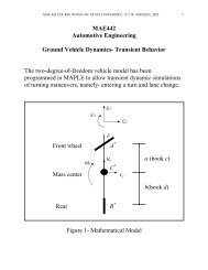
Fig. 1. Reflection <strong>and</strong> <strong>transmission</strong> of an <strong>in</strong>cident wave <strong>in</strong> <strong>beams</strong> conta<strong>in</strong><strong>in</strong>g semi-<strong>in</strong>f<strong>in</strong>ite delam<strong>in</strong>ation: (a) open delam<strong>in</strong>ation <strong>and</strong><br />
(b) closed delam<strong>in</strong>ation.
678<br />
ARTICLE IN PRESS<br />
W.-C. Yuan et al. / Journal of Sound <strong>and</strong> Vibration 313 (2008) 676–695<br />
conta<strong>in</strong><strong>in</strong>g semi-<strong>in</strong>f<strong>in</strong>ite delam<strong>in</strong>ation. Only the closed delam<strong>in</strong>ation is considered <strong>and</strong> the results of<br />
symmetric delam<strong>in</strong>ation are given <strong>in</strong> comparison with the closed delam<strong>in</strong>ation modeled by equivalent<br />
<strong>in</strong>homogeneity.<br />
The purpose of this paper is to present an analytical method for analyz<strong>in</strong>g the wave behavior of the<br />
delam<strong>in</strong>ated beam <strong>and</strong> for determ<strong>in</strong><strong>in</strong>g the (power) <strong>reflection</strong> from <strong>and</strong> <strong>transmission</strong> through a semi-<strong>in</strong>f<strong>in</strong>ite<br />
delam<strong>in</strong>ated <strong>composite</strong> beam. The <strong>composite</strong> beam is modeled us<strong>in</strong>g Timoshenko beam theory. Upon wave<br />
<strong>in</strong>cidence on the beam the waveguide propagates toward the delam<strong>in</strong>ation, then splits <strong>in</strong>to two waveguides <strong>in</strong><br />
the delam<strong>in</strong>ated sub-<strong>beams</strong>, each with its own higher cut-off frequency. The crack surfaces may experience<br />
partially closed or open <strong>in</strong> a time-vary<strong>in</strong>g manner. To analytically model the delam<strong>in</strong>ation region, two extreme<br />
cases signify<strong>in</strong>g the extreme cases of delam<strong>in</strong>ated surface condition dur<strong>in</strong>g the wave propagation are<br />
considered. One is that the delam<strong>in</strong>ation surfaces are completely open. It means there is no contact between<br />
two sub-<strong>beams</strong>. The transmitted waves <strong>in</strong> sub-<strong>beams</strong> are <strong>in</strong>dependent of each other; while the other assumed<br />
that the delam<strong>in</strong>ated surfaces are completely closed, that has been discussed <strong>in</strong> Ref. [13], the surfaces are <strong>in</strong><br />
contact. These two cases are shown <strong>in</strong> Fig. 1(a) <strong>and</strong> (b), respectively. The two cases are described as open <strong>and</strong><br />
closed delam<strong>in</strong>ations here<strong>in</strong>.<br />
The paper is organized as follows. Dispersion relation, phase <strong>and</strong> group velocities of Timoshenko <strong>beams</strong> are<br />
analyzed <strong>in</strong> Section 2. The <strong>reflection</strong> <strong>and</strong> <strong>transmission</strong> coefficients for the open <strong>and</strong> closed delam<strong>in</strong>ations are<br />
derived, respectively, <strong>in</strong> Section 3. In Section 4 the power <strong>reflection</strong> <strong>and</strong> <strong>transmission</strong> <strong>and</strong> power distribution<br />
among transmitted wave modes are analyzed. Numerical results are conducted <strong>in</strong> Section 5. Comparison of<br />
results from analytical solutions <strong>and</strong> f<strong>in</strong>ite element method is made <strong>in</strong> Section 6. F<strong>in</strong>ally conclusions are drawn<br />
<strong>in</strong> Section 7.<br />
2. Dispersion relations of Timoshenko <strong>beams</strong><br />
Based on Timoshenko beam theory, the general displacements of the <strong>composite</strong> beam can be described as<br />
Uðx; z; tÞ ¼uðx; tÞþzcðx; tÞ; Vðx; z; tÞ ¼0; Wðx; z; tÞ ¼wðx; tÞ, (1)<br />
where x-axis is the centroidal axis of the (sub-) beam. u(x,t) is the axial displacement of the beam <strong>in</strong> the<br />
x-direction. c(x, t) is the rotation of the cross-section of the beam about the y-axis; w(x,t) is the transverse<br />
displacement of the beam <strong>in</strong> the z-direction. The non-vanish<strong>in</strong>g stra<strong>in</strong> components provided by Eq. (1) are<br />
x ¼ u ;x þ zc ;x ; g xz ¼ w ;x þ c. (2)<br />
The equilibrium equations for a symmetric lam<strong>in</strong>ated beam [14] can be written as<br />
where<br />
N; x ¼ I 1 €u; V; x ¼ I 1 €w; M; x V ¼ I 2<br />
€ c, (3)<br />
N ¼<br />
Z h=2<br />
h=2<br />
s x dz;<br />
V ¼<br />
Z h=2<br />
h=2<br />
t xz dz;<br />
M ¼<br />
Z h=2<br />
h=2<br />
s x z dz. (4)<br />
N, V, <strong>and</strong> M are the axial force, shear force, <strong>and</strong> bend<strong>in</strong>g moment per unit beam width of the <strong>composite</strong><br />
beam; s x <strong>and</strong> t xz are the axial <strong>and</strong> shear stresses, respectively, h is the thickness of the beam<br />
I 1 ¼<br />
Z h=2<br />
h=2<br />
r dz <strong>and</strong> I 2 ¼<br />
Z h=2<br />
h=2<br />
rz 2 dz (5)<br />
are the translational <strong>and</strong> rotational <strong>in</strong>ertia per unit beam width, respectively, <strong>and</strong> r is the mass density of the<br />
lam<strong>in</strong>ated beam.
For the <strong>composite</strong> beam, the stiffness of an off-axis <strong>composite</strong> can be written <strong>in</strong> the follow<strong>in</strong>g form [14]:<br />
2<br />
3<br />
C 11 C 12 C 13 0 0 C 16<br />
C 12 C 22 C 23 0 0 C 26<br />
C 13 C 23 C 33 0 0 C 36<br />
C ¼<br />
. (6)<br />
0 0 0 C 44 C 45 0<br />
6<br />
4 0 0 0 C 45 C 55 0 7<br />
5<br />
C 16 C 26 C 36 0 0 C 66<br />
S<strong>in</strong>ce the transverse shear stra<strong>in</strong> is taken as a constant through the beam thickness, a shear adjustment<br />
coefficient k is <strong>in</strong>troduced such that transverse shear force would be equal to the actual shear force <strong>in</strong><br />
magnitude. Consider<strong>in</strong>g the plane stra<strong>in</strong> <strong>in</strong> the y-direction (i.e., second equation of Eq. (1)), the constitutive<br />
relations between stress <strong>and</strong> stra<strong>in</strong> can be simplified as<br />
s x ¼ C 11 x ; t xz ¼ k 2 C 55 g xz , (7)<br />
where k 2 ¼ p 2 /12 is the transverse shear correction factor which is determ<strong>in</strong>ed by the match of the cut-off<br />
frequency of the beam theory with that obta<strong>in</strong>ed from the Rayleigh–Lamb equation [15]. If the plane stress<br />
condition is imposed <strong>in</strong> the beam, the coefficients of Eq. (7) are replaced by C ~ 11 ¼ C 11 C 2 12 =C 22,<br />
~C 55 ¼ C 55 C 2 45 =C 44.<br />
Then the axis force, bend<strong>in</strong>g moment, <strong>and</strong> shear force can be written us<strong>in</strong>g Eqs. (4) <strong>and</strong> (7) by<br />
N ¼ A 11 u; x ; M ¼ D 11 c; x ; V ¼ k 2 A 55 ðw; x þ cÞ, (8)<br />
where the extensional, shear, <strong>and</strong> bend<strong>in</strong>g stiffnesses are def<strong>in</strong>ed by [14]<br />
A 11 ¼<br />
Z h=2<br />
h=2<br />
C 11 dz;<br />
ARTICLE IN PRESS<br />
W.-C. Yuan et al. / Journal of Sound <strong>and</strong> Vibration 313 (2008) 676–695 679<br />
A 55 ¼<br />
Z h=2<br />
h=2<br />
C 55 dz;<br />
D 11 ¼<br />
Z h=2<br />
The equilibrium equation given by Eq. (3) can be expressed <strong>in</strong> terms of displacements as<br />
A 11 u ;xx ¼ I 1 €u,<br />
h=2<br />
C 11 z 2 dz. (9)<br />
(10a)<br />
k 2 A 55 ðw ;xx þ c ;x Þ¼I 1 €w,<br />
(10b)<br />
D 11 c ;xx k 2 A 55 ðw ;x þ cÞ ¼I 2 c. € (10c)<br />
For plane wave solutions the displacements <strong>in</strong> one-dimensional beam are represented by<br />
u ¼ U 0 e iðkx otÞ ; w ¼ W 0 e iðkx otÞ ; c ¼ C 0 e iðkx otÞ . (11)<br />
The dispersion relation of flexural waves can be expressed via Eqs. (10b) <strong>and</strong> (10c) as follows:<br />
ðk 2 A 55 k 2 I 1 o 2 ÞðD 11 k 2 þ k 2 A 55 I 2 o 2 Þ k 4 A 2 55 k2 ¼ 0. (12)<br />
There are four roots of Eq. (12):<br />
2<br />
sffiffiffiffiffiffiffiffiffiffiffiffiffiffiffiffiffiffiffiffiffiffiffiffiffiffiffiffiffiffiffiffiffiffiffiffiffiffiffiffiffiffiffiffiffiffiffiffiffiffi3<br />
k j ¼ 1 <br />
2 1 þ c2 l<br />
c 2<br />
l<br />
k 2 c 2 þ 1 <br />
s qo 4 1 c 2 <br />
1=2 2<br />
4<br />
l 5<br />
o<br />
k 2 c 2 (13)<br />
s c l<br />
for (j ¼ 1,2) <strong>and</strong> not<strong>in</strong>g p k 3 ¼ k 1 , k 4 ¼ k 2 ,<br />
In Eq. (13) c s ¼<br />
ffiffiffiffiffiffiffiffiffiffiffiffiffiffi p<br />
A 55 =I 1 <strong>and</strong> c l ¼<br />
ffiffiffiffiffiffiffiffiffiffiffiffiffiffi<br />
D 11 =I 2 are shear <strong>and</strong> plate wave velocities, respectively. For a<br />
unidirectional <strong>composite</strong> p beam with rectangular cross-section, these velocities are <strong>in</strong>dependent of beam<br />
thickness <strong>and</strong> q ¼<br />
ffiffiffiffiffiffiffiffiffiffiffi p<br />
I 2 =I 1 ¼ h=<br />
ffiffiffiffiffi<br />
12 .<br />
Us<strong>in</strong>g the follow<strong>in</strong>g non-dimensional variables,<br />
x ¼ x=h;<br />
w ¼ w=h,<br />
t ¼ t=t; k ¼ kh; o ¼ ot, (14)
680<br />
ARTICLE IN PRESS<br />
W.-C. Yuan et al. / Journal of Sound <strong>and</strong> Vibration 313 (2008) 676–695<br />
where the reference length scale is the thickness of the (sub-)beam h <strong>and</strong> a typical time scale t ¼ h/c s , the<br />
result<strong>in</strong>g non-dimensional dispersion relation is<br />
2 sffiffiffiffiffiffiffiffiffiffiffiffiffiffiffiffiffiffiffiffiffiffiffiffiffiffiffiffiffiffiffiffiffiffiffiffiffiffiffi3<br />
k j ¼<br />
ða þ k2 Þ 12<br />
2ak 2 <br />
ao 2 þ 1 <br />
1=2<br />
1 1 2<br />
4<br />
5<br />
4 a k 2 o ðj ¼ 1; 2Þ; k 3 ¼ k 1 ; k 4 ¼ k 2 , (15)<br />
where a ¼ (c l /c s ) 2 .<br />
The cut-off frequency of the A 1 mode can be simply determ<strong>in</strong>ed by sett<strong>in</strong>g k 2 ¼ 0 <strong>in</strong> Eq. (13), which gives<br />
o c ¼ kc s =q. (16)<br />
Phase velocities <strong>and</strong> group velocities are given by<br />
c p ¼ o=k; c g ¼ do=dk. (17)<br />
When frequencies approach <strong>in</strong>f<strong>in</strong>ity, the wave velocity becomes non-dispersive. Accord<strong>in</strong>g to Eqs. (13) <strong>and</strong><br />
(17), the phase <strong>and</strong> group velocities of two flexural modes can be simply derived<br />
c g0 ¼ kc s ; c g1 ¼ c l as o !1.<br />
Clearly these two group velocities do not depend on the thickness of the beam.<br />
In the relatively low frequency range, ooo c , the Timoshenko beam experiences a pair of propagat<strong>in</strong>g waves<br />
(one positive-go<strong>in</strong>g <strong>and</strong> one negative-go<strong>in</strong>g) plus two evanescent (near-field) waves, the value of k be<strong>in</strong>g purely<br />
imag<strong>in</strong>ary. The pair of propagat<strong>in</strong>g waves is called the lowest fundamental flexural A 0 wave modes. These two<br />
near-field waves can be regarded as positive- <strong>and</strong> negative-go<strong>in</strong>g attenuat<strong>in</strong>g waves which decay exponentially<br />
with the wave travel distance. Beyond the cut-off frequency o c , two pairs of propagat<strong>in</strong>g waves (two positivego<strong>in</strong>g<br />
<strong>and</strong> two negative-go<strong>in</strong>g) co-exist, called A 0 <strong>and</strong> A 1 modes. Thus, with an <strong>in</strong>crease of frequency, a nonpropagat<strong>in</strong>g<br />
mode can decay more slowly <strong>and</strong> eventually becomes a propagat<strong>in</strong>g mode.<br />
A general solution of Eq. (10b) <strong>and</strong> Eq. (10c) is given by<br />
wðx; tÞ ¼ X4<br />
j¼1<br />
a j e iðk jx otÞ ; cðx; tÞ ¼ X4<br />
j¼1<br />
F j a j e iðk jx otÞ , (18)<br />
where F j ¼ i½ðo=kc s Þ 2 k 2 j Š=k j ðj ¼ 1; 2Þ, F 3 ¼ F 1 <strong>and</strong> F 4 ¼ F 2 . The amplitudes a j may be complex.<br />
For the extensional wave mode governed by Eq. (10a), there exists a pair of propagat<strong>in</strong>g waves (one<br />
positive-go<strong>in</strong>g <strong>and</strong> negative-go<strong>in</strong>g). The wave is non-dispersive based on the Timoshenko beam theory whose<br />
dispersion relation is given by<br />
p<br />
k e ¼<br />
ffiffiffiffiffiffiffiffiffiffiffiffiffiffi<br />
I 1 =A 11 o. (19)<br />
3. Reflection <strong>and</strong> <strong>transmission</strong> matrices<br />
When a propagat<strong>in</strong>g time harmonic wave is <strong>in</strong>cident upon a discont<strong>in</strong>uity, it is scattered <strong>in</strong>to waves reflected<br />
from <strong>and</strong> transmitted through the discont<strong>in</strong>uity whose magnitudes <strong>and</strong> phases can be quantified by <strong>reflection</strong><br />
<strong>and</strong> <strong>transmission</strong> matrices. The total wave field can be expressed as a sum of the <strong>in</strong>cident wave field <strong>and</strong> the<br />
scattered wave field. The mode <strong>in</strong>cident on the delam<strong>in</strong>ation results <strong>in</strong> both reflected <strong>and</strong> transmitted waves of<br />
all orders of the wave modes that could exist <strong>in</strong> the beam for a given frequency. It is assumed that far away<br />
from the discont<strong>in</strong>uity the reflected <strong>and</strong> transmitted waves are plane waves. The <strong>in</strong>cident time harmonic wave<br />
<strong>in</strong>duces not only propagat<strong>in</strong>g waves (real wavenumber) <strong>and</strong> non-propagat<strong>in</strong>g evanescent near-field waves<br />
(purely imag<strong>in</strong>ary wavenumber). In this section, a propagat<strong>in</strong>g flexural wave at far-field excited on<br />
a unidirectional <strong>composite</strong> beam <strong>in</strong>cident upon a semi-<strong>in</strong>f<strong>in</strong>ite delam<strong>in</strong>ation is studied. The far field is<br />
def<strong>in</strong>ed here as the distance where the contribution of non-propagat<strong>in</strong>g wave can be neglected. Two extreme<br />
cases of delam<strong>in</strong>ated surface conditions: non-contact (open) <strong>and</strong> fully contact (closed) delam<strong>in</strong>ations, are<br />
considered, respectively. The <strong>reflection</strong> <strong>and</strong> <strong>transmission</strong> matrices of both open <strong>and</strong> closed delam<strong>in</strong>ations are<br />
derived separately.
ARTICLE IN PRESS<br />
W.-C. Yuan et al. / Journal of Sound <strong>and</strong> Vibration 313 (2008) 676–695 681<br />
3.1. Open delam<strong>in</strong>ation<br />
Consider a slender beam conta<strong>in</strong><strong>in</strong>g a semi-<strong>in</strong>f<strong>in</strong>ite delam<strong>in</strong>ation shown <strong>in</strong> Fig. 1(a), the orig<strong>in</strong> of the<br />
coord<strong>in</strong>ate is located at the tip of the delam<strong>in</strong>ation. The beam can be divided <strong>in</strong>to two regions. The left region<br />
is the un-delam<strong>in</strong>ated region which conta<strong>in</strong>s both <strong>in</strong>cident <strong>and</strong> reflected waves; while the right region<br />
encompasses the two delam<strong>in</strong>ated sub-<strong>beams</strong>. S<strong>in</strong>ce the delam<strong>in</strong>ation surfaces are open, there is no contact<br />
pressure between the surfaces. Only positive-go<strong>in</strong>g wave exists <strong>in</strong> the two sub-<strong>beams</strong>, which refers to the<br />
transmitted wave.<br />
Consider<strong>in</strong>g an <strong>in</strong>cident flexural wave travel<strong>in</strong>g <strong>in</strong> the positive x-direction, <strong>in</strong> the left un-delam<strong>in</strong>ated<br />
region (xp0) when the excitation frequency is greater than the cut-off frequency, the wave fields consist<br />
of two positive-go<strong>in</strong>g <strong>in</strong>cident flexural waves <strong>and</strong> two negative-go<strong>in</strong>g reflected flexural waves that can be<br />
written as<br />
w 0 ¼ a e ik1x þ b e ik2x þ a r e ik1x þ b r e ik2x ,<br />
(20a)<br />
c 0 ¼ F 1 a e ik1x þ F 2 b e ik 2x<br />
F 1 a r e ik 1x<br />
F 2 b r e ik2x .<br />
(20b)<br />
Due to the moment cont<strong>in</strong>uity on the junction, an <strong>in</strong>duced extensional wave may also be reflected from the<br />
discont<strong>in</strong>uity <strong>and</strong> transmitted <strong>in</strong>to two sub-<strong>beams</strong>. The negative-go<strong>in</strong>g reflected extensional wave <strong>in</strong> the left<br />
region can be expressed as<br />
u 0 ¼ c r e ikex ,<br />
(20c)<br />
where the time dependence term e iot has been suppressed here <strong>and</strong> hereafter. When the excitation frequency<br />
is below the cut-off frequency, i.e., ooo c , the second pair wave mode becomes evanescent s<strong>in</strong>ce the<br />
wavenumber k 2 is purely imag<strong>in</strong>ary. The choice of the sign <strong>in</strong> k 2 is dictated by the condition that the reflected<br />
wave field is f<strong>in</strong>ite as x- N. In this case, the sign of k 2 is deliberately chosen to be negative. The coefficients<br />
of a <strong>and</strong> b represents the amplitude of <strong>in</strong>cident wave depend<strong>in</strong>g on the details of the load<strong>in</strong>g away from the<br />
discont<strong>in</strong>uity. When excited at far field <strong>in</strong> the low frequency b can be set to zero. In the limit when frequency<br />
approaches <strong>in</strong>f<strong>in</strong>ity, the group velocities of the two modes are given by Eq. (17).<br />
In the right delam<strong>in</strong>ated region (xX0) where the crack surfaces are completely open, the displacements<br />
of the two <strong>in</strong>dependent sub-<strong>beams</strong> are denoted by u 1 , w 1 , c 1 , u 2 , w 2 , c 2 . The subscripts 1 <strong>and</strong> 2<br />
denote the upper <strong>and</strong> lower sub-<strong>beams</strong>, respectively. S<strong>in</strong>ce waves are transmitted from the <strong>in</strong>cident waves<br />
through the discont<strong>in</strong>uity, the general solutions of displacement for the transmitted waves <strong>in</strong> each sub-beam<br />
are given by<br />
c n ¼ F ðnÞ<br />
w n ¼ a ðnÞ<br />
t e ikðnÞ<br />
1 aðnÞ t<br />
e ikðnÞ 1 x þ F ðnÞ<br />
1 x þ b ðnÞ<br />
2 bðnÞ t<br />
t<br />
e ikðnÞ 2 x , (21a)<br />
e ikðnÞ 2 x ðn ¼ 1; 2Þ, (21b)<br />
u n ¼ c ðnÞ<br />
t e ikðnÞ e x , (21c)<br />
(n)<br />
where superscripts (1) <strong>and</strong> (2) denote the parameters associated with each sub-beam. The wavenumber k j<br />
<strong>and</strong> F (n) j can be readily obta<strong>in</strong>ed by substitut<strong>in</strong>g the stiffness <strong>and</strong> moment of <strong>in</strong>ertia perta<strong>in</strong><strong>in</strong>g to the each subbeam<br />
<strong>in</strong> Eqs. (4), (5) <strong>and</strong> (9). Accord<strong>in</strong>g to Eq. (19), the wavenumber of the extensional wave is <strong>in</strong>dependent of<br />
beam thickness imply<strong>in</strong>g k e ¼ k (1) e ¼ k (2) e .<br />
The cut-off frequency of each sub-beam can be written as follows:<br />
qffiffiffiffiffiffiffiffiffiffiffiffiffiffiffi<br />
o ð1Þ<br />
c ¼ kc s =q ð1Þ ; o ð2Þ<br />
c ¼ kc s =q ð2Þ , (22)<br />
where q ðnÞ ¼ (n ¼ 1,2).<br />
The group velocities of two flexural wave modes <strong>in</strong> each sub-beam at <strong>in</strong>f<strong>in</strong>ite frequency, accord<strong>in</strong>g to<br />
Eq. (17), are<br />
I ðnÞ ðnÞ<br />
2<br />
=I<br />
1<br />
c ðnÞd<br />
g0<br />
¼ kc s ; c ðnÞd<br />
g1<br />
¼ c l as o !1 ðn ¼ 1; 2Þ, (23)<br />
where the superscript d denotes the delam<strong>in</strong>ated <strong>beams</strong>.
682<br />
ARTICLE IN PRESS<br />
W.-C. Yuan et al. / Journal of Sound <strong>and</strong> Vibration 313 (2008) 676–695<br />
h<br />
N 0 1<br />
M 0<br />
V 2<br />
V<br />
N 2<br />
M 2<br />
M 1<br />
V 0 N 1<br />
h 1<br />
h 2<br />
Fig. 2. Free body diagram of delam<strong>in</strong>ated beam.<br />
The amplitudes of these waves <strong>in</strong>volv<strong>in</strong>g n<strong>in</strong>e unknowns (a r , b r , c r , a t (1) , b t (1) , c t (1) , a t (2) , b t (2) , c t (2) ) can be<br />
determ<strong>in</strong>ed from the follow<strong>in</strong>g cont<strong>in</strong>uity <strong>and</strong> equilibrium conditions at the junction, x ¼ 0 as shown <strong>in</strong> Fig. 2<br />
w 0 ¼ w 1 ¼ w 2 ; c 0 ¼ c 1 ¼ c 2 ; u 1 ¼ u 0 þ h 2<br />
2 c 0; u 2 ¼ u 0<br />
h 1<br />
2 c 0,<br />
N 0 ¼ N 1 þ N 2 ; M 0 ¼ M 1 þ M 2 þ h 2<br />
2 N 1<br />
h 1<br />
2 N 2; V 0 ¼ V 1 þ V 2 . (24)<br />
Substitut<strong>in</strong>g Eqs. (20) <strong>and</strong> (21) together with Eq. (8) <strong>in</strong>to Eq. (24) leads to the follow<strong>in</strong>g matrix form:<br />
2<br />
32<br />
3<br />
1 1 0 1 1 0 0 0 0 a 2<br />
3<br />
r 1 1<br />
1 1 0 0 0 0 1 1 0<br />
b r<br />
1 1<br />
F 1 F 2 0 F ð1Þ<br />
1<br />
F ð1Þ<br />
2<br />
0 0 0 0<br />
c r<br />
F 1 F 2<br />
F 1 F 2 0 0 0 0 F ð2Þ<br />
1<br />
F ð2Þ<br />
2<br />
0<br />
a ð1Þ<br />
t<br />
F F 1 h 2 F 2 h 2 2 0 0 2 0 0 0<br />
b ð1Þ<br />
1 F 2<br />
<br />
a<br />
t<br />
¼<br />
F 1 h 2 F 2 h 2<br />
F 1 h 1 F 2 h 1 2 0 0 0 0 0 2<br />
c ð1Þ<br />
, (25)<br />
t<br />
F 1 h 1 F 2 h b<br />
1<br />
0 0 h 0 0 h 1 0 0 h 2<br />
a ð2Þ<br />
t<br />
0 0<br />
6<br />
4<br />
k 1 F 1 k 2 F 2 0 a ð1Þ<br />
1<br />
a ð1Þ<br />
2<br />
b a ð2Þ<br />
1<br />
a ð2Þ<br />
2<br />
b 76<br />
54<br />
b ð2Þ<br />
7 6<br />
t 5<br />
k 1 F 1 k 2 F<br />
7<br />
4<br />
2 5<br />
g 1 g 2 0 g ð1Þ<br />
1<br />
g ð1Þ<br />
2<br />
0 g ð2Þ<br />
1<br />
g ð2Þ<br />
2<br />
0 c ð2Þ g<br />
t<br />
1 g 2<br />
where a ðnÞ<br />
m<br />
¼ kðnÞ m F m ðnÞðh<br />
n=hÞ 3 , b ¼ 6(h 1 h 2 /h 3 )k e , g (n) m ¼ h n (ik (n) m +F (n) m ), m, n ¼ 1,2.<br />
The coefficients of reflected <strong>and</strong> transmitted waves can be symbolically represented <strong>in</strong> terms of the<br />
coefficients of the <strong>in</strong>cident wave <strong>in</strong> the follow<strong>in</strong>g relation:<br />
½a r ; b r ; c r Š T ¼ R 32 ½a; bŠ T ,<br />
(26a)<br />
½a ð1Þ<br />
t<br />
; b ð1Þ<br />
t<br />
; c ð1Þ<br />
t Š T ¼ T ð1Þ<br />
32 ½a; bŠT ,<br />
(26b)<br />
½a ð2Þ<br />
t ; b ð2Þ<br />
t ; c ð2Þ<br />
t Š T ¼ T ð2Þ<br />
32 ½a; bŠT ,<br />
(26c)<br />
where R 3 2 , T ð1Þ<br />
32<br />
, <strong>and</strong> Tð2Þ<br />
32<br />
denote <strong>reflection</strong> <strong>and</strong> the <strong>transmission</strong> matrices whose components are complex <strong>in</strong><br />
general. For example, <strong>in</strong> <strong>reflection</strong> matrix R 3 2 the component R 12 means the second <strong>in</strong>cident flexural wave<br />
mode converts <strong>in</strong>to the first reflected flexural mode from the discont<strong>in</strong>uity. Similarly, the transmitted mode<br />
conversion also occurs. The extensional wave mode may be <strong>in</strong>duced <strong>in</strong> the <strong>composite</strong> beam. This means the<br />
flexural wave will partly transform to the extensional mode when the <strong>in</strong>cident wave is reflected from the<br />
delam<strong>in</strong>ation tip or transmitted <strong>in</strong>to the delam<strong>in</strong>ated region. The proportion of the extensional mode<br />
conversion compared with the flexural mode conversion depends on the <strong>in</strong>cident wave frequency <strong>and</strong> position<br />
of the delam<strong>in</strong>ation <strong>in</strong> the thickness direction. This will be discussed <strong>in</strong> detail <strong>in</strong> Section 5.<br />
3.2. Closed delam<strong>in</strong>ation<br />
The displacements of the left un-delam<strong>in</strong>ated region are the same as <strong>in</strong> the open delam<strong>in</strong>ation case.<br />
Denot<strong>in</strong>g the contact pressure between the two delam<strong>in</strong>ated surfaces as p(x, t), as shown <strong>in</strong> Fig. 1(b), with the<br />
identical transverse displacement, i.e., ^w ¼ w 1 ¼ w 2 , the follow<strong>in</strong>g govern<strong>in</strong>g equations of flexural wave can be
ARTICLE IN PRESS<br />
W.-C. Yuan et al. / Journal of Sound <strong>and</strong> Vibration 313 (2008) 676–695 683<br />
derived:<br />
k 2 A ð1Þ<br />
55 ð ^w; xx þ c 1 ; x Þ¼I ð1Þ<br />
1 €^w þ p, (27a)<br />
D ð1Þ<br />
11 c 1; xx k 2 A ð1Þ<br />
55 ð ^w ;x þ c 1 Þ¼I ð1Þ<br />
2 € c 1 , (27b)<br />
k 2 A ð2Þ<br />
55 ð ^w; xx þ c 2 ; x Þ¼I ð2Þ<br />
1 €^w p, (27c)<br />
D ð2Þ<br />
11 c 2; xx k 2 A ð2Þ<br />
55 ð ^w ;x þ c 2 Þ¼I ð2Þ € 2<br />
c 2 . (27d)<br />
The contact pressure p can be elim<strong>in</strong>ated by comb<strong>in</strong><strong>in</strong>g Eqs. (27a) <strong>and</strong> (27c), to obta<strong>in</strong><br />
k 2 ðA 55 ^w; xx þ A ð1Þ<br />
55 c 1; x þ A ð2Þ<br />
55 c 2; x Þ¼I 1<br />
€^w. (28)<br />
If the displacements are <strong>in</strong>troduced as<br />
^w ¼ ^W e ið ^kx otÞ ; c 1 ¼ C 1 e ið ^kx otÞ ; c 2 ¼ C 2 e ið ^kx otÞ . (29)<br />
Then by substitution of Eq. (29) <strong>in</strong>to Eqs. (28), (27b), <strong>and</strong> (27d), the dispersion relation can be determ<strong>in</strong>ed<br />
as follows:<br />
82<br />
k 2 A 55 ^k2 ik 2 A ð1Þ ^k 55<br />
ik 2 A ð2Þ ^k<br />
3 2<br />
39<br />
55 I det ik 2 A ð1Þ ^k 55<br />
D ð1Þ ^k 1 0 0<br />
><<br />
2 11<br />
þ k 2 A ð1Þ<br />
6<br />
55<br />
0 7<br />
4<br />
ik 2 A ð2Þ ^k 55<br />
0 D ð2Þ ^k<br />
5 o2 0 I ð1Þ<br />
>=<br />
6 2<br />
0 7<br />
4<br />
5 ¼ 0. (30)<br />
>:<br />
2 11<br />
þ k 2 A ð2Þ 0 0 I ð2Þ<br />
2<br />
>;<br />
55<br />
The results give rise to three flexural wave modes. Loosely these modes can be related to the<br />
fundamental flexural mode of the un-delam<strong>in</strong>ated portion of the beam, A 0 (0)d , <strong>and</strong> the other two<br />
related to the A 1 mode <strong>in</strong> the upper <strong>and</strong> lower sub-<strong>beams</strong>, A 1 (1)d <strong>and</strong> A 1 (2)d , respectively. Two cut-off<br />
frequencies can be readily proved to be identical to those <strong>in</strong> the open delam<strong>in</strong>at<strong>in</strong>g case. When the frequencies<br />
approach <strong>in</strong>f<strong>in</strong>ity, accord<strong>in</strong>g to Eqs. (30) <strong>and</strong> (17), the group velocities of the three flexural modes can be<br />
exactly derived<br />
c ð0Þd<br />
g0<br />
¼ kc s ; c ð1Þd<br />
g1<br />
¼ c ð2Þd<br />
g1<br />
¼ c l as o !1. (31)<br />
The general solution of the positive-go<strong>in</strong>g transmitted flexural waves <strong>in</strong> the delam<strong>in</strong>ated region can be<br />
conveniently written as<br />
^w ¼ a t e i ^k 0 x þ b ð1Þ<br />
t e i ^k 1 x þ b ð2Þ<br />
t e i ^k 2 x , (32a)<br />
c n ¼ G ðnÞ<br />
0 a t e i ^k 0 x þ G ðnÞ<br />
1 bð1Þ t<br />
e i ^k 1 x þ G ðnÞ<br />
2 bð2Þ t e i ^k 2 x ðn ¼ 1; 2Þ, (32b)<br />
where G ðnÞ<br />
j ¼ði ^k j =½ðoq ðnÞ Þ=ðkc ðnÞ<br />
s ÞŠ 2 ½q ðnÞ ð ^k j =kÞðc ðnÞ<br />
l<br />
=c ðnÞ<br />
s ÞŠ 2 1Þ, (n ¼ 1,2 <strong>and</strong> j ¼ 0,1,2).<br />
The extensional waves <strong>in</strong> the two sub-<strong>beams</strong> are the same as <strong>in</strong> the open delam<strong>in</strong>ation case. There are a total<br />
of eight amplitudes (a r , b r , c r , a t , b (1) t , b (2) t , c (1) t , c (2) t ) which can be determ<strong>in</strong>ed from the follow<strong>in</strong>g cont<strong>in</strong>uity<br />
<strong>and</strong> equilibrium conditions at x ¼ 0.<br />
w 0 ¼ ^w; c 0 ¼ c 1 ¼ c 2 ; u 1 ¼ u 0 þ h 2<br />
2 c 0; u 2 ¼ u 0<br />
h 1<br />
2 c 0,<br />
N 0 ¼ N 1 þ N 2 ; M 0 ¼ M 1 þ M 2 þ h 2<br />
2 N 1<br />
h 1<br />
2 N 2; V 0 ¼ V 1 þ V 2 . (33)
684<br />
ARTICLE IN PRESS<br />
W.-C. Yuan et al. / Journal of Sound <strong>and</strong> Vibration 313 (2008) 676–695<br />
Substitut<strong>in</strong>g Eqs. (20) <strong>and</strong> (32) together with Eq. (8) <strong>in</strong>to Eq. (33), the equations can be written <strong>in</strong> matrix<br />
form:<br />
2<br />
32<br />
3 2<br />
3<br />
1 1 0 1 1 1 0 0 a r 1 1<br />
F 1 F 2 0 G ð1Þ<br />
0<br />
G ð1Þ<br />
1<br />
G ð1Þ<br />
2<br />
0 0<br />
b r<br />
F 1 F 2<br />
F 1 F 2 0 G ð2Þ<br />
0<br />
G ð2Þ<br />
1<br />
G ð2Þ<br />
2<br />
0 0<br />
c r<br />
F 1 F 2<br />
F 1 h 2 F 2 h 2 2 0 0 0 2 0<br />
a t<br />
<br />
F 1 h 2 F 2 h 2<br />
a<br />
F 1 h 1 F 2 h 1 2 0 0 0 0 2<br />
b ð1Þ<br />
t<br />
¼<br />
F 1 h 1 F 2 h 1<br />
, (34)<br />
b<br />
0 0 h 0 0 0 h 1 h 2<br />
b ð2Þ<br />
t<br />
0 0<br />
6<br />
4 k 1 F 1 k 2 F 2 0 u 0 u 1 u 2 b b 76<br />
54<br />
c ð1Þ 7 6<br />
t 5 4 k 1 F 1 k 2 F 2<br />
7<br />
5<br />
g 1 g 2 0 n 0 n 1 n 2 0 0<br />
g 1 g 2<br />
where u j ¼ ^k j ðG ð1Þ<br />
j ðh 1 =hÞ 3 þ G ð2Þ<br />
j ðh 2 =hÞ 3 Þ, n j ¼ h 1 ði ^k j þ G ð1Þ<br />
j Þþh 2 ði ^k j þ G ð2Þ<br />
j Þ (j ¼ 0,1,2). The reflected <strong>and</strong><br />
transmitted waves are related to those of <strong>in</strong>cident wave via the follow<strong>in</strong>g relation:<br />
½a t ; b ð1Þ<br />
t<br />
½a r ; b r ; c r Š T ¼ R 32 ½a; bŠ T ,<br />
; b ð2Þ<br />
t<br />
c ð2Þ<br />
t<br />
(35a)<br />
; c ð1Þ<br />
t ; c ð2Þ<br />
t Š T ¼ T 52 ½a; bŠ T , (35b)<br />
where R 3 2 <strong>and</strong> T 5 2 denote <strong>reflection</strong> <strong>and</strong> <strong>transmission</strong> matrices, respectively. For fully contacted<br />
delam<strong>in</strong>ated surfaces, the <strong>transmission</strong> matrix conta<strong>in</strong>s three coupled flexural modes <strong>and</strong> two extensional<br />
modes <strong>in</strong> two sub-<strong>beams</strong>, respectively. The constant pressure distribution p from Eq. (27a) or (27c) <strong>in</strong>dicates<br />
the pressure reverses its sign over the delam<strong>in</strong>ated region, imply<strong>in</strong>g that the delam<strong>in</strong>ated surfaces may be<br />
partially open or closed.<br />
4. Power <strong>reflection</strong> <strong>and</strong> <strong>transmission</strong><br />
The wave cont<strong>in</strong>uously carries energy as it propagates, the rate of energy transport <strong>in</strong>to one end of a crosssection<br />
of the beam be<strong>in</strong>g, on average, equal to the rate out of the other end of the cross-section if no energy<br />
dissipation is <strong>in</strong>volved. This speed of transport, or power flow, is given by the rate of work of <strong>in</strong>ternal forces<br />
<strong>and</strong> moments act<strong>in</strong>g on a beam cross-section. A useful representation of the <strong>in</strong>tensity of wave can be<br />
represented by an average of power P over time. Over a period t 0 , the time-averaged power flow /PS per unit<br />
beam width <strong>in</strong> Timoshenko beam is given by<br />
hPi ¼<br />
1 Z t0<br />
ðV _w þ M c<br />
t _ þ N _uÞ dt, (36)<br />
0<br />
0<br />
where t 0 ¼ 2p/o. Both <strong>in</strong>cident <strong>and</strong> reflected waves exist <strong>in</strong> the un-delam<strong>in</strong>ated region. S<strong>in</strong>ce only flexural<br />
wave is excited at the far field. The third term of Eq. (36) associated with extensional wave vanishes.<br />
Substitut<strong>in</strong>g Eqs. (20a) <strong>and</strong> (20b) together with the force–displacement relations Eq. (8) <strong>in</strong>to Eq. (36), the<br />
time-averaged power flow of the <strong>in</strong>cident wave over a cycle can be written as<br />
hP i i ¼ l 1 jaj 2 þ l 2 jbj 2 Hðo o c Þ, (37)<br />
where l m ¼ 1 2 o½k2 A 55 k m þ D 11 k m jF m j 2 þ k 2 A 55 ImðF m ÞŠ; m ¼ 1; 2. The Heaviside function H used signifies<br />
that the term associated with evanescent wave does not carry energy when ooo c . In this case, only the first<br />
term of Eq. (37) rema<strong>in</strong>s.<br />
For the reflected wave <strong>in</strong> un-delam<strong>in</strong>ated region, the total power flow of reflected wave can be written as<br />
follows:<br />
hP r<br />
i ¼ l 1 ja r j 2 þ l 2 jb r j 2 Hðo o c Þþl e jc r j 2 , (38)<br />
where l e ¼ 1 2 ok eA 11 .<br />
For a semi-<strong>in</strong>f<strong>in</strong>ite delam<strong>in</strong>ation, the <strong>in</strong>cident waves transmit waves <strong>in</strong>to delam<strong>in</strong>ated regions. In the open<br />
delam<strong>in</strong>ated surfaces, each sub-beam can be considered as a separate s<strong>in</strong>gle beam with its own stiffness <strong>and</strong>
thickness. Thus, power flow of transmitted waves <strong>in</strong> the open delam<strong>in</strong>ated region can be expressed as<br />
hP t i ðnÞ<br />
open ¼ lðnÞ 1 a ðnÞ<br />
t 2 þ l ðnÞ<br />
<br />
2<br />
b ðnÞ 2 t Hðo o ðnÞ<br />
c ÞþlðnÞ e c ðnÞ<br />
t 2 ðn ¼ 1; 2Þ, (39)<br />
where l ðnÞ<br />
m ¼ 1 2 o½k2 A ðnÞ<br />
55 kðnÞ m þ DðnÞ 11 kðnÞ m F ðnÞ 2 m þ k 2 A ðnÞ ðnÞ<br />
55<br />
ImðF m ÞŠ,lðnÞ e ¼ 1 2 ok eA ðnÞ<br />
11<br />
, m, n ¼ 1,2.<br />
The superscripts (1) <strong>and</strong> (2) denote the two separated sub-<strong>beams</strong> <strong>in</strong> the open delam<strong>in</strong>ated region.<br />
In the closed delam<strong>in</strong>ated region, two sub-<strong>beams</strong> are constra<strong>in</strong>ed with identical transverse displacement.<br />
Similarly the power flow of transmitted wave <strong>in</strong> the closed delam<strong>in</strong>ated region can be written as follows:<br />
hP t i ðnÞ<br />
closed ¼ ZðnÞ 0<br />
ja t j 2 þ Z ðnÞ<br />
<br />
1<br />
b ð1Þ 2 t Hðo o ð1Þ<br />
c ÞþZðnÞ <br />
2<br />
b ð2Þ 2 t Hðo o ð2Þ<br />
c ÞþlðnÞ e c ðnÞ<br />
t 2 , (40)<br />
where Z ðnÞ<br />
j ¼ 1 2 o½k2 A ðnÞ ^k 55 j þ ^k j D ðnÞ<br />
11 GðnÞ j 2 þ k 2 A ðnÞ<br />
55<br />
Im ðGðnÞ j ÞŠ (n ¼ 1,2, j ¼ 0,1,2).<br />
The superscripts (1) <strong>and</strong> (2) denote the two coupled sub-<strong>beams</strong> <strong>in</strong> the closed delam<strong>in</strong>ated region.<br />
The ratios of the reflected <strong>and</strong> transmitted power (energy) to the <strong>in</strong>cident energy are def<strong>in</strong>ed as<br />
h<br />
R ¼ P ri<br />
hP i i ; T ðnÞ<br />
open ¼ h P ti ðnÞ<br />
open<br />
; T ðnÞ<br />
closed<br />
hP i i<br />
¼ h P ti ðnÞ<br />
closed<br />
ðn ¼ 1; 2Þ. (41)<br />
hP i i<br />
The energy conservation implies<br />
R þ X2<br />
n¼1<br />
T ðnÞ ¼ 1. (42)<br />
For transmitted waves <strong>in</strong> the delam<strong>in</strong>ated region, power (energy) ratios associated with each wave mode can<br />
be described as:<br />
l ð1Þ<br />
T A 0<br />
open ¼ 1 a ð1Þ<br />
t 2 þ l ð2Þ<br />
1 a ð2Þ<br />
t 2<br />
hP t i ð1Þ<br />
open þ h P ti ð2Þ ; T A 1<br />
open ¼ lð1Þ <br />
2<br />
b ð1Þ 2 t þ l ð2Þ<br />
<br />
2<br />
b ð2Þ 2<br />
l ð1Þ<br />
t<br />
open<br />
hP t i ð1Þ<br />
open þ h P ti ð2Þ ; T s 0<br />
open ¼ e c ð1Þ<br />
t 2 þ l ð2Þ<br />
e c ð2Þ<br />
t 2<br />
open<br />
hP t i ð1Þ<br />
open þ h P ti ð2Þ ,<br />
open<br />
<br />
Z ð1Þ<br />
T A 0<br />
closed ¼<br />
0<br />
þ Z ð2Þ<br />
0<br />
ja t j 2<br />
hP t i ð1Þ<br />
closed þ h P ti ð2Þ ; T A 1<br />
closed ¼ ðZð1Þ 1<br />
þ Z ð2Þ<br />
1 Þ bð1Þ 2 t þðZ ð1Þ<br />
2<br />
þ Z ð2Þ<br />
2 Þ bð2Þ 2<br />
t<br />
closed<br />
hP t i ð1Þ<br />
closed þ h P ti ð2Þ ,<br />
closed<br />
l ð1Þ<br />
T s 0<br />
closed ¼ e c ð1Þ<br />
t 2 þ l ð2Þ<br />
e c ð2Þ<br />
t 2<br />
hP t i ð1Þ<br />
closed þ h P ti ð2Þ , (43)<br />
closed<br />
where the superscripts A 0 , A 1 , S 0 denote the term related to different propagat<strong>in</strong>g modes.<br />
5. Numerical results<br />
ARTICLE IN PRESS<br />
W.-C. Yuan et al. / Journal of Sound <strong>and</strong> Vibration 313 (2008) 676–695 685<br />
A unidirectional <strong>composite</strong> beam made of IM7/5250-4 graphite/epoxy material is chosen as an example <strong>in</strong><br />
this section. The fibers are aligned with the beam axis <strong>and</strong> beam cross-section is rectangular. The material<br />
properties of the <strong>composite</strong> are shown <strong>in</strong> Table 1.<br />
For the <strong>composite</strong> beam where the delam<strong>in</strong>ated surfaces are modeled to be open, the group velocities of sub<strong>beams</strong><br />
<strong>and</strong> their own cut-off frequencies can be readily determ<strong>in</strong>ed by Eqs. (14)–(16) us<strong>in</strong>g perta<strong>in</strong><strong>in</strong>g<br />
geometries <strong>in</strong> each sub-beam. In contrast, the <strong>composite</strong> beam where delam<strong>in</strong>ated surfaces are completely<br />
closed, the group velocities of closed delam<strong>in</strong>ated regions given by Eq. (30) are compared with those from the<br />
Table 1<br />
Material properties of IM7/5250-4 <strong>composite</strong><br />
E L (GPa) E T (GPa) G LT (Gpa) G TZ (GPa) n LT n TZ r (kg/m 3 )<br />
168 9.31 5.17 3.45 0.33 0.4 1.61
686<br />
ARTICLE IN PRESS<br />
W.-C. Yuan et al. / Journal of Sound <strong>and</strong> Vibration 313 (2008) 676–695<br />
c g /c s<br />
6<br />
5<br />
4<br />
3<br />
2<br />
1<br />
0<br />
A 0<br />
0<br />
A 0<br />
(0)d<br />
(2) (1)<br />
ω c ω c ω c<br />
A 1<br />
0<br />
A 1<br />
(2)d<br />
A 1<br />
(1)d<br />
0 1 2 3 4<br />
c g /c s<br />
1.0<br />
0.8<br />
0.6<br />
0.4<br />
0.2<br />
A 0<br />
0<br />
A 0<br />
(0)d<br />
0<br />
0 0.05 0.1 0.15 0.2 0.25 0.3<br />
ω/ω c<br />
ω/ω c<br />
Fig. 3. Group velocities of flexural modes <strong>in</strong> both un-delam<strong>in</strong>ated region (A 0 0 , A 1 0 ) <strong>and</strong> closed delam<strong>in</strong>ated region (A 0 (0)d , A 1 (1)d , A 1 (2)d ), solid<br />
l<strong>in</strong>e: un-delam<strong>in</strong>ated region; dotted l<strong>in</strong>e: closed delam<strong>in</strong>ated region. (a) All flexural wave modes <strong>and</strong> (b) close-up view of A 0 modes <strong>in</strong> the<br />
lower frequency doma<strong>in</strong>.<br />
Magnitude<br />
1.5<br />
1.2<br />
0.9<br />
0.6<br />
0.3<br />
(2) (1)<br />
ω c ω c ω c<br />
R 11<br />
R 21<br />
180<br />
135<br />
90<br />
45<br />
-45<br />
0 -90<br />
0 1 2 3 4<br />
ω/ω c<br />
0<br />
Phase (deg)<br />
Magnitude<br />
7<br />
6<br />
5<br />
4<br />
3<br />
2<br />
1<br />
R 12<br />
R 22<br />
(2) (1)<br />
ω c ω c ω c<br />
180<br />
135<br />
90<br />
45<br />
-45<br />
0<br />
-90<br />
0 1 2 3 4<br />
ω/ω c<br />
0<br />
Phase (deg)<br />
Fig. 4. Reflection coefficients (R jk , for j, k ¼ 1,2) at h 1 /h ¼ 0.4 under open delam<strong>in</strong>ation condition (solid l<strong>in</strong>e: magnitude; dotted l<strong>in</strong>e:<br />
phase). <strong>Wave</strong> <strong>reflection</strong> from (a) first flexural mode <strong>and</strong> (b) second flexural mode.<br />
un-delam<strong>in</strong>ated given by Eq. (13), shown <strong>in</strong> Fig. 3. In this figure, the delam<strong>in</strong>ation is located at h 1 /h ¼ 0.4. The<br />
superscripts 0 <strong>and</strong> d <strong>in</strong> the figure denote the un-delam<strong>in</strong>ated <strong>and</strong> delam<strong>in</strong>ated region of the beam, respectively.<br />
It can be concluded from Fig. 3(a) that the group velocity curves of two A 0 modes are very close <strong>in</strong> the whole<br />
frequency doma<strong>in</strong>. However, there is a slightly lower group velocities of A 0 mode <strong>in</strong> the closed delam<strong>in</strong>ated<br />
region compared with those <strong>in</strong> the un-delam<strong>in</strong>ated region when the frequencies are below 0.3o c , which can be<br />
seen <strong>in</strong> Fig. 3(b). It is ma<strong>in</strong>ly due to the reduction of the bend<strong>in</strong>g stiffness <strong>in</strong> the delam<strong>in</strong>ated region.<br />
In addition, both A 0 modes tend to reach transverse wave velocity multiplied by the shear correction factor<br />
(kc s ) as the frequency approaches <strong>in</strong>f<strong>in</strong>ity. Additional two flexural modes <strong>in</strong> the closed delam<strong>in</strong>ated region<br />
associated with each sub-beam region appear. Their cut-off frequencies are greater than that <strong>in</strong> the undelam<strong>in</strong>ated<br />
region because of the lower thickness values. As the frequency becomes higher, the group velocity<br />
curves of two modes reach the same values (c l ) <strong>in</strong> the un-delam<strong>in</strong>ated region.<br />
The magnitudes <strong>and</strong> phases of <strong>reflection</strong> <strong>and</strong> <strong>transmission</strong> coefficients versus dimensionless frequency are<br />
shown <strong>in</strong> Figs. 4–9 for a given delam<strong>in</strong>ated position h 1 /h ¼ 0.4. The left vertical axes denote the magnitudes<br />
while right vertical axes denotes the phases. Both open <strong>and</strong> closed delam<strong>in</strong>ations are considered <strong>in</strong> these<br />
figures. Sub-figures (a) <strong>and</strong> (b) describes the modes transmitted <strong>and</strong> converted from the first <strong>and</strong> second<br />
flexural <strong>in</strong>cident waves, respectively.
ARTICLE IN PRESS<br />
W.-C. Yuan et al. / Journal of Sound <strong>and</strong> Vibration 313 (2008) 676–695 687<br />
Magnitude<br />
180<br />
ω/ω c<br />
3<br />
0.6<br />
R<br />
0<br />
12<br />
R 0<br />
R<br />
2<br />
22<br />
11<br />
0.3<br />
R<br />
-45<br />
-45<br />
21 1<br />
(2) (1)<br />
ω c ω c ω c<br />
1.5<br />
180 7<br />
ω c<br />
(2)<br />
ω c<br />
(1)<br />
ω c<br />
ω/ω c<br />
1.2<br />
135<br />
6<br />
135<br />
90<br />
5<br />
90<br />
0.9<br />
4<br />
45<br />
45<br />
0<br />
-90 0<br />
-90<br />
0 1 2 3 4<br />
0 1 2 3 4<br />
Phase (deg)<br />
Fig. 5. Reflection coefficients (R jk , for j, k ¼ 1,2) (h 1 /h ¼ 0.4) under closed delam<strong>in</strong>ation condition (solid l<strong>in</strong>e: magnitude; dotted l<strong>in</strong>e:<br />
phase). <strong>Wave</strong> <strong>reflection</strong> from (a) first flexural mode <strong>and</strong> (b) second flexural mode.<br />
Magnitude<br />
Phase (deg)<br />
2.0<br />
(2) (1)<br />
ω c ω c ω c<br />
135<br />
25<br />
(2) (1)<br />
ω c ω c ω c<br />
180<br />
Magnitude<br />
1.5<br />
1.0<br />
0.5<br />
(1)<br />
(1) T 21<br />
T 11<br />
(1)<br />
T 31<br />
90<br />
45<br />
0<br />
-45<br />
Phase (deg)<br />
Magnitude<br />
20<br />
15<br />
10<br />
5<br />
(1)<br />
T 22<br />
(1)<br />
T 12<br />
(1)<br />
T 32<br />
135<br />
90<br />
45<br />
0<br />
-45<br />
-90<br />
Phase (deg)<br />
0 -90<br />
0 1 2 3 4<br />
ω/ω c<br />
0<br />
-135<br />
0 1 2 3 4<br />
ω/ω c<br />
Fig. 6. Magnitudes <strong>and</strong> phases of <strong>transmission</strong> coefficients ðT ð1Þ<br />
jk ; for j ¼ 1,2,3, k ¼ 1,2) <strong>in</strong> upper sub-beam (h 1/h ¼ 0.4) under open<br />
delam<strong>in</strong>ation condition (solid l<strong>in</strong>e: magnitude; dotted l<strong>in</strong>e: phase). <strong>Wave</strong> <strong>transmission</strong> from (a) first flexural mode <strong>and</strong> (b) second flexural<br />
mode.<br />
2.0<br />
(2) (1)<br />
ω c ω c ω c<br />
135<br />
25<br />
(2) (1)<br />
ω c ω c ω c<br />
180<br />
Magnitude<br />
1.5<br />
1.0<br />
0.5<br />
(2)<br />
T 11<br />
(2)<br />
T 21<br />
(2)<br />
T 31<br />
90<br />
45<br />
0<br />
-45<br />
Phase (deg)<br />
Magnitude<br />
20<br />
15<br />
10<br />
5<br />
(2)<br />
T 22<br />
(2)<br />
T 12<br />
(2)<br />
T 32<br />
135<br />
90<br />
45<br />
0<br />
-45<br />
-90<br />
Phase (deg)<br />
0<br />
-90<br />
0 1 2 3 4<br />
ω/ω c<br />
0<br />
-135<br />
0 1 2 3 4<br />
ω/ω c<br />
Fig. 7. Magnitudes <strong>and</strong> phases of <strong>transmission</strong> coefficients (T ð2Þ<br />
jk , for j ¼ 1,2,3, k ¼ 1,2) <strong>in</strong> lower sub-beam (h 1/h ¼ 0.4) under open<br />
delam<strong>in</strong>ation condition (solid l<strong>in</strong>e: magnitude; dotted l<strong>in</strong>e: phase). <strong>Wave</strong> <strong>transmission</strong> from (a) first flexural mode <strong>and</strong> (b) second flexural<br />
mode.
688<br />
ARTICLE IN PRESS<br />
W.-C. Yuan et al. / Journal of Sound <strong>and</strong> Vibration 313 (2008) 676–695<br />
Magnitude<br />
2<br />
1.5<br />
1<br />
0.5<br />
(2) (1)<br />
ω c ω c ω c<br />
T 11<br />
T 21 T 31<br />
0<br />
0 1 2 3 4<br />
180<br />
135<br />
90<br />
45<br />
0<br />
-45<br />
Phase (deg)<br />
Magnitude<br />
7<br />
6<br />
(2) (1)<br />
ω c ω c ω c<br />
180<br />
13<br />
5 T 32<br />
90<br />
45<br />
4 T 22<br />
0<br />
3<br />
2<br />
1<br />
0<br />
T 12<br />
-45<br />
-90<br />
-135<br />
-180<br />
0 1 2 3 4<br />
Phase (deg)<br />
ω/ω c<br />
ω/ω c<br />
Fig. 8. Magnitudes <strong>and</strong> phases of three flexural <strong>transmission</strong> coefficients (T jk , for j ¼ 1,2,3, k ¼ 1,2) <strong>in</strong> delam<strong>in</strong>ated region (h 1 /h ¼ 0.4)<br />
under closed delam<strong>in</strong>ation condition (solid l<strong>in</strong>e: magnitude; dotted l<strong>in</strong>e: phase). <strong>Wave</strong> <strong>transmission</strong> from (a) first flexural mode <strong>and</strong><br />
(b) second flexural mode.<br />
0.15<br />
(2) (1)<br />
ω c ω c ω c<br />
180<br />
25<br />
(2) (1)<br />
ω c ω c ω c<br />
180<br />
Magnitude<br />
0.12<br />
0.09<br />
0.06<br />
0.03<br />
T 41<br />
135<br />
90<br />
45<br />
0<br />
-45<br />
-90<br />
Phase (deg)<br />
Magnitude<br />
20<br />
15<br />
10<br />
5<br />
T 42<br />
T 52<br />
135<br />
90<br />
45<br />
0<br />
-45<br />
-90<br />
Phase (deg)<br />
T 51<br />
0 1 2 3 4<br />
0<br />
0 1 2 3 4<br />
-135<br />
0<br />
-135<br />
ω/ω c<br />
ω/ω c<br />
Fig. 9. Magnitudes <strong>and</strong> phases of two extensional <strong>transmission</strong> coefficients (T jk , for j ¼ 4,5, k ¼ 1,2) <strong>in</strong> delam<strong>in</strong>ated region (h 1 /h ¼ 0.4)<br />
under closed delam<strong>in</strong>ation condition (solid l<strong>in</strong>e: magnitude; dotted l<strong>in</strong>e: phase). <strong>Wave</strong> <strong>transmission</strong> from (a) first flexural mode <strong>and</strong><br />
(b) second flexural mode.<br />
It is clearly seen by compar<strong>in</strong>g Figs. 4 <strong>and</strong> 5 that, as expected, the <strong>reflection</strong> coefficients are very <strong>in</strong>sensitive<br />
to the delam<strong>in</strong>ated surface conditions. The <strong>reflection</strong> magnitude (reflectivity) monotonically deceases as<br />
frequencies <strong>in</strong>crease except |R 12 |, where the <strong>reflection</strong> starts to <strong>in</strong>crease <strong>and</strong> then decrease after o/o c ¼ 0.6. In<br />
the lower frequency doma<strong>in</strong>, where the frequency is below the cut-off frequency <strong>in</strong> the un-delam<strong>in</strong>ated region,<br />
although the <strong>reflection</strong> coefficient |R 21 | has larger magnitude, the wave is non-propagat<strong>in</strong>g evanescent type<br />
<strong>and</strong> decays exponentially from the delam<strong>in</strong>ation tip. When the excitation source conta<strong>in</strong>s the second<br />
propagat<strong>in</strong>g mode, |R 12 |<strong>and</strong>|R 22 | decrease rapidly near o c . The phases of flexural <strong>reflection</strong> coefficients<br />
depend strongly on the frequency when ooo c (1) . The <strong>reflection</strong> coefficients |R 31 |<strong>and</strong>|R 32 | (not shown <strong>in</strong> the<br />
figures) are virtually zero <strong>and</strong> phases are shifted by 901, imply<strong>in</strong>g that there is almost no extensional wave<br />
reflected from the two flexural modes. The <strong>in</strong>duced extensional waves arise primarily from the selfequilibrat<strong>in</strong>g<br />
forces to ensure equilibrium between the sub-<strong>beams</strong>.<br />
S<strong>in</strong>ce the two extreme delam<strong>in</strong>ation surface conditions <strong>in</strong>volve different formulation <strong>and</strong> result<strong>in</strong>g different<br />
displacement fields, the <strong>transmission</strong> coefficients may vary between open <strong>and</strong> closed delam<strong>in</strong>ations, which are<br />
shown <strong>in</strong> Figs. 6–9. Figs. 6 <strong>and</strong> 7 give the <strong>transmission</strong> coefficients of two sub-<strong>beams</strong> for open delam<strong>in</strong>ation<br />
surfaces, respectively; while Figs. 8 <strong>and</strong> 9 present the <strong>transmission</strong> coefficients of flexural <strong>and</strong> extensional<br />
modes under closed delam<strong>in</strong>ation surfaces, respectively. Compar<strong>in</strong>g the curves among Figs. 6–9(a),
ARTICLE IN PRESS<br />
W.-C. Yuan et al. / Journal of Sound <strong>and</strong> Vibration 313 (2008) 676–695 689<br />
the coefficients strongly depend on the frequency <strong>in</strong> the frequency ooo c ; beyond this frequency, there is<br />
almost no mode conversion, i.e., |T n1 |E0 (n ¼ 2–5); all the first flexural wave energy directly transmits from<br />
the un-delam<strong>in</strong>ated region <strong>in</strong>to the delam<strong>in</strong>ated region, i.e., |T 11 |E1. Comparatively, the coefficients<br />
converted from the second mode are much higher than the one converted from the first mode when ooo c , but<br />
these modes <strong>in</strong>volve no power <strong>transmission</strong> s<strong>in</strong>ce the evanescent wave cannot transport the energy. And these<br />
coefficients vary rapidly with frequencies, especially at the cut-off frequency.<br />
The coefficients of flexural modes converted from the second mode, such as |T 12 |<strong>and</strong>|T 22 |<strong>in</strong>Figs. 6(b) <strong>and</strong><br />
7(b), |T 12 |, |T 22 | <strong>and</strong> |T 32 |<strong>in</strong>Fig. 8(b), are significantly reduced when the frequency is beyond the cut-off<br />
frequency (o4o c ). It should be noticed that the coefficients of extensional mode converted from the second<br />
mode, such as |T 32 |<strong>in</strong>Figs. 6(b) <strong>and</strong> 7(b), |T 42 |, <strong>and</strong> |T 52 |<strong>in</strong>Fig. 9(b), <strong>in</strong>crease with the vary<strong>in</strong>g frequency.<br />
This can be expla<strong>in</strong>ed by the fact that the second flexural mode c(x, t) <strong>in</strong>troduces the rotation of the crosssection.<br />
This rotation <strong>in</strong>duces large longitud<strong>in</strong>al motion <strong>in</strong> the sub-<strong>beams</strong> to ma<strong>in</strong>ta<strong>in</strong> the rotation<br />
compatibility at the junction of the delam<strong>in</strong>ation tip.<br />
Us<strong>in</strong>g the power flow expression <strong>in</strong> Eq. (41), the reflected <strong>and</strong> transmitted energies for both open <strong>and</strong> closed<br />
delam<strong>in</strong>ation surfaces are shown <strong>in</strong> Fig. 10. Numerical results based on the formulation show that the energy<br />
is conserved for all frequencies. In this study, two types of <strong>in</strong>cident waves are chosen: b ¼ 0 (the first flexural<br />
wave mode only) <strong>and</strong> b/a ¼ 1 (two <strong>in</strong>cident flexural waves have identical magnitudes). When o4o c , the two<br />
cases (open <strong>and</strong> closed delam<strong>in</strong>ation) have very close results of the energy <strong>transmission</strong> <strong>and</strong> <strong>reflection</strong> ratios<br />
are almost <strong>in</strong>dependent of the delam<strong>in</strong>ation surface conditions. A notable difference <strong>in</strong> the energy<br />
<strong>transmission</strong> ratios occur <strong>in</strong> the lower frequency doma<strong>in</strong> for these two delam<strong>in</strong>ation surface conditions.<br />
Moreover, there is a marked difference between Fig. 10(a) <strong>and</strong> (b) when o4o c , because the second flexural<br />
mode is <strong>in</strong>volved. And there is a high energy <strong>reflection</strong> when the frequency is just beyond the cut-off frequency<br />
o c shown <strong>in</strong> Fig. 10(b). This is because <strong>in</strong> this frequency doma<strong>in</strong> the wave transmitt<strong>in</strong>g <strong>in</strong>to the two sub-<strong>beams</strong><br />
are evanescent, only one propagat<strong>in</strong>g mode transmitted <strong>in</strong>to the delam<strong>in</strong>ation region. Thus all the energy of<br />
the second flexural mode is reflected back <strong>in</strong>to the un-delam<strong>in</strong>ated region.<br />
The waves transmitted <strong>in</strong> the delam<strong>in</strong>ation region from the <strong>in</strong>cident flexural waves experience mode<br />
conversion of the extensional wave <strong>and</strong> the flexural wave vary<strong>in</strong>g with the frequency can be obta<strong>in</strong>ed. Fig. 11<br />
shows the transmitted energy ratios among various modes for different excitation frequencies. It can be<br />
concluded that the A 0 mode is converted most of the energy when the frequency is lower than the cut-off<br />
frequency <strong>in</strong> the un-delam<strong>in</strong>ated region. While the frequency is beyond o c <strong>and</strong> b ¼ 0 (see Fig. 11(a)), which<br />
means there is no second <strong>in</strong>cident mode, A 0 mode transmitted almost all of the energy, thus there is no mode<br />
conversion. When o4o c <strong>and</strong> b/a ¼ 1 (see Fig. 11(b)), portion of the transmitted energy is shared by the<br />
extensional mode. This suggests that the extensional motion <strong>in</strong> the two sub-<strong>beams</strong> is mostly converted from<br />
Reflected <strong>and</strong> transmitted energy ratio<br />
1.0<br />
0.8<br />
0.6<br />
0.4<br />
0.2<br />
0<br />
(2) (1)<br />
ω c ω c ω c<br />
T (2)<br />
T (1)<br />
R<br />
0 1 2 3 4<br />
Reflected <strong>and</strong> transmitted energy ratio<br />
1.0<br />
0.8<br />
0.6<br />
0.4<br />
T (1)<br />
(2) (1)<br />
ω c ω c ω c<br />
T (2) T (1)<br />
T (2)<br />
0.2<br />
R<br />
R<br />
0<br />
0 1 2 3 4<br />
ω/ω c<br />
ω/ω c<br />
Fig. 10. Reflected energy ratio (R) <strong>and</strong> transmitted energy ratios (T (i) , for i ¼ 1,2) (h 1 /h ¼ 0.4) (solid l<strong>in</strong>e: open delam<strong>in</strong>ation; dotted l<strong>in</strong>e:<br />
closed delam<strong>in</strong>ation) (a) b ¼ 0; <strong>and</strong> (b) b/a ¼ 1.
690<br />
ARTICLE IN PRESS<br />
W.-C. Yuan et al. / Journal of Sound <strong>and</strong> Vibration 313 (2008) 676–695<br />
Transmitted energy ratio<br />
1.0<br />
0.8<br />
0.6<br />
0.4<br />
0.2<br />
(1)<br />
ω c<br />
(2)<br />
ω c ω c<br />
A 0<br />
Transmitted energy ratio<br />
1.0<br />
0.8<br />
0.6<br />
0.4<br />
0.2<br />
A 0<br />
A 0<br />
(2) (2)<br />
ω c ω c<br />
S 0<br />
A 1<br />
S 0<br />
0<br />
0 1 2 3 4<br />
0<br />
0 1 2 3 4<br />
ω/ω c<br />
ω/ω c<br />
Fig. 11. Transmitted energy ratios among various wave modes (A 0 , S 0 , A 1 )ath 1 /h ¼ 0.4 (solid l<strong>in</strong>e: open delam<strong>in</strong>ation; dotted l<strong>in</strong>e: closed<br />
delam<strong>in</strong>ation): (a) b ¼ 0 <strong>and</strong> (b) b/a ¼ 1.<br />
Reflected energy ratio<br />
0.012<br />
0.010<br />
0.008<br />
0.006<br />
0.004<br />
0.002<br />
Transmitted energy ratio<br />
1.0<br />
0.8<br />
0.6<br />
0.4<br />
0.2<br />
0<br />
0<br />
0 0.1 0.2 0.3 0.4 0.5 0 0.1 0.2 0.3 0.4 0.5<br />
Delam<strong>in</strong>ation position h 1 /h Delam<strong>in</strong>ation position h 1 /h<br />
Fig. 12. Reflected energy ratio (R) <strong>and</strong> transmitted energy ratios (T (i) , for i ¼ 1,2) versus the delam<strong>in</strong>ation position (o ¼ 0.1o c ):<br />
(a) reflected energy ratio <strong>and</strong> (b) transmitted energy ratio (solid l<strong>in</strong>e: open delam<strong>in</strong>ation; dotted l<strong>in</strong>e: closed delam<strong>in</strong>ation).<br />
c(x,t), rotation of the cross-section of the beam. The other flexural modes A 1 is present when the frequency is<br />
beyond the cut-off frequency of the sub-beam. In the all frequency doma<strong>in</strong>, the transmitted energy of wave<br />
modes is <strong>in</strong>sensitive to the delam<strong>in</strong>ation surface conditions.<br />
Fig. 12 shows the effect of various delam<strong>in</strong>ated positions <strong>in</strong> the thickness direction on the reflected <strong>and</strong><br />
transmitted energy ratios at a given frequency o ¼ 0.1o c . At this frequency, the transmitted wave<br />
only conta<strong>in</strong>s S 0 <strong>and</strong> A 0 modes, <strong>and</strong> the energy ratios for extensional wave versus delam<strong>in</strong>ation<br />
position are shown <strong>in</strong> Fig. 13. The reflected energy ratios of two cases are slightly different when h 1 /h is<br />
below 0.4, while match<strong>in</strong>g well when h 1 /h is close to 0.5. It is because the contact pressure will be larger when<br />
the delam<strong>in</strong>ation be<strong>in</strong>g more asymmetrical. Especially, <strong>in</strong> the case of symmetric delam<strong>in</strong>ation, i.e., h 1 /h ¼ 0.5,<br />
there is no contact pressure, <strong>and</strong> the results of two cases are identical. This reason is also true for the energy<br />
<strong>transmission</strong> ratios. Generally, the reflected energy <strong>in</strong>creases as the delam<strong>in</strong>ation position is closer to the<br />
middle plane, <strong>and</strong> reaches maximum value at h 1 /h ¼ 0.5. This can be simply expla<strong>in</strong>ed by the reduction of<br />
the bend<strong>in</strong>g stiffness <strong>in</strong> the delam<strong>in</strong>ated region, the maximum occurr<strong>in</strong>g at h 1 /h ¼ 0.5. The energy ratio of the<br />
transmitted extensional mode <strong>in</strong>creases monotonically with <strong>in</strong>crease of h 1 /h, <strong>and</strong> reach the maximum value at<br />
h 1 /h ¼ 0.5.
ARTICLE IN PRESS<br />
W.-C. Yuan et al. / Journal of Sound <strong>and</strong> Vibration 313 (2008) 676–695 691<br />
0.06<br />
0.05<br />
Transmitted energy ratio<br />
0.04<br />
0.03<br />
0.02<br />
0.01<br />
0<br />
0<br />
0.1 0.2<br />
0.3<br />
Delam<strong>in</strong>ation position h 1 /h<br />
0.4<br />
0.5<br />
Fig. 13. Transmitted energy ratio (T S 0<br />
) for extensional wave mode S 0 versus the delam<strong>in</strong>ation position (o ¼ 0.1o c ) (solid l<strong>in</strong>e: open<br />
delam<strong>in</strong>ation; dotted l<strong>in</strong>e: closed delam<strong>in</strong>ation).<br />
M<br />
S 1 S 2<br />
h<br />
l<br />
l<br />
l<br />
S 3<br />
L<br />
Fig. 14. The schematic of the beam modeled <strong>in</strong> us<strong>in</strong>g f<strong>in</strong>ite elements.<br />
6. Comparison with results from f<strong>in</strong>ite element method<br />
In order to verify the accuracy of the analytical method of power <strong>reflection</strong> <strong>and</strong> <strong>transmission</strong> <strong>in</strong> a semi<strong>in</strong>f<strong>in</strong>ite<br />
delam<strong>in</strong>ation us<strong>in</strong>g the two extreme delam<strong>in</strong>ated surface conditions, a f<strong>in</strong>ite element analysis us<strong>in</strong>g<br />
MSC software is conducted to model the wave propagation <strong>in</strong> the delam<strong>in</strong>ated beam. The delam<strong>in</strong>ated<br />
surfaces are modeled by gap elements that impose normal forces to avoid <strong>in</strong>terpenetration on the portion of<br />
the delam<strong>in</strong>ation surfaces dur<strong>in</strong>g the wave propagation. The true <strong>in</strong>terface condition would probably <strong>in</strong>volve<br />
frictional slippage <strong>and</strong> dissipation. Fig. 14 shows the schematic of the delam<strong>in</strong>ated cantilever beam with the<br />
geometry: l ¼ 150 mm, L ¼ 550 mm, <strong>and</strong> h ¼ 1.8 mm. Sensor S 1 located at middle plane of the un-delam<strong>in</strong>ated<br />
region is used to measure the <strong>in</strong>cident wave <strong>and</strong> reflected wave. Sensors S 2 <strong>and</strong> S 3 at the middle plane of two<br />
sub-<strong>beams</strong> are used to measure the transmitted wave, respectively. It should be noticed that S 2 <strong>and</strong> S 3 conta<strong>in</strong><br />
both transverse <strong>and</strong> longitud<strong>in</strong>al displacements at the middle plane, while S 1 only conta<strong>in</strong>s the transverse<br />
displacement. The element is chosen by a plane stra<strong>in</strong> 4-node rectangular element. Note that the size of each<br />
element depends on the frequency of the guided wave. It must be satisfied that there are more than 8 elements<br />
<strong>in</strong> a wavelength to m<strong>in</strong>imize the numerical distortion.<br />
Sections 3 <strong>and</strong> 4 discussed the (power) <strong>reflection</strong> <strong>and</strong> <strong>transmission</strong> <strong>in</strong>cident upon the delam<strong>in</strong>ation of<br />
harmonic flexural waves of a s<strong>in</strong>gle frequency. In practice it is unlikely to generate a s<strong>in</strong>gle frequency wave <strong>in</strong><br />
limited time duration, <strong>in</strong> this section a narrowb<strong>and</strong> <strong>in</strong>cident wave is excited to exam<strong>in</strong>e the <strong>in</strong>teraction of flexural<br />
waves with delam<strong>in</strong>ation us<strong>in</strong>g f<strong>in</strong>ite element method. Thus, a Fourier <strong>in</strong>tegral is needed to calculate the wave<br />
response. The <strong>in</strong>cident flexural wave is generated at the left of the cantilever beam by excit<strong>in</strong>g a concentrated<br />
moment at the middle node of the left end of the beam, which can be mathematically described by<br />
<br />
MðtÞ ¼M 0 ½HðtÞ Hðt 5=f 0 ÞŠ 1 cos 2pf <br />
0t<br />
s<strong>in</strong> 2pf<br />
5<br />
0 t. (44)
692<br />
ARTICLE IN PRESS<br />
W.-C. Yuan et al. / Journal of Sound <strong>and</strong> Vibration 313 (2008) 676–695<br />
This wave packet denotes a five-peaked narrowb<strong>and</strong> signal modulated by a Hann<strong>in</strong>g w<strong>in</strong>dow, which the wave<br />
energy is concentrated around the central frequency f 0 . The excitation signal is chosen, such that the central<br />
frequency is 50 kHz (approximately 0.1 of the cut-off frequency f c ). This signal has no significant energy above<br />
the cut-off frequency of the A 1 mode, thus only first the flexural mode is excited. The wave transmitted<br />
displacement will be firstly generated at the left end of the beam, described as a 0 (t). In this l<strong>in</strong>ear transient wave<br />
analysis, the wave propagates at the same frequency content of the applied excitation signal. The frequency<br />
spectrum of the transient wave displacement can be obta<strong>in</strong>ed us<strong>in</strong>g Fourier transform <strong>and</strong> can be written as<br />
A 0 ðoÞ ¼<br />
Z þ1<br />
1<br />
a 0 ðtÞ e iot dt. (45)<br />
The magnitudes of wave packets received by three sensors <strong>in</strong> frequency doma<strong>in</strong> could be obta<strong>in</strong>ed by<br />
multiply<strong>in</strong>g the <strong>reflection</strong> <strong>and</strong> <strong>transmission</strong> coefficients on <strong>in</strong>cident wave packet. Meanwhile, there is phase-shift<br />
caused by the wave propagation distance shown <strong>in</strong> Fig. 14. This would be also multiplied on the <strong>in</strong>cident wave.<br />
Then the signal received by each sensor is the superposition of the <strong>in</strong>cident <strong>and</strong> scattered wave <strong>in</strong>clud<strong>in</strong>g<br />
<strong>transmission</strong> <strong>and</strong> <strong>reflection</strong> (if any) waves:<br />
A S1 ðoÞ ¼A 0 ðoÞ e ik 1l þ R 11 A 0 ðoÞ e 3ik 1l ,<br />
(46a)<br />
A S2 ðoÞ ¼T ð1Þ<br />
11 A 0ðoÞ e 2ik 1lþik ð1Þ<br />
1 l ; C S2 ðoÞ ¼T ð1Þ<br />
31 A 0ðoÞ e 2ik 1lþik e l , (46b)<br />
A S3 ðoÞ ¼T ð2Þ<br />
11 A 0ðoÞ e 2ik 1lþik ð2Þ<br />
1 l ; C S3 ðoÞ ¼T ð2Þ<br />
31 A 0ðoÞ e 2ik 1lþik e l , (46c)<br />
where A S1 ðoÞ, A S2 ðoÞ <strong>and</strong> A S3 ðoÞ denote the flexural signals received by S 1 , S 2 ,<strong>and</strong>S 3 , respectively, <strong>and</strong> C S2 ðoÞ<br />
<strong>and</strong> C S3 ðoÞ represent the extensional signals received, respectively, by S 2 <strong>and</strong> S 3 . For example, A S1 ðoÞ consists<br />
of <strong>in</strong>cident wave <strong>and</strong> reflected wave. The <strong>in</strong>cident wave propagat<strong>in</strong>g to S 1 experiences a phase shift by a distance<br />
l <strong>and</strong> the reflected wave by 3l. S<strong>in</strong>ce both waves propagate <strong>in</strong> the un-delam<strong>in</strong>ated region, a s<strong>in</strong>gle wavenumber k 1<br />
is used.<br />
Then the signal <strong>in</strong> the time doma<strong>in</strong> can be symbolically represented by us<strong>in</strong>g its <strong>in</strong>verse Fourier transform<br />
shown as follows:<br />
aðtÞ ¼ 1 Z 1<br />
AðoÞ e iot do, (47)<br />
2p 1<br />
where A(o) represents A S1 ðoÞ, A S2 ðoÞ, A S3 ðoÞ, C S2 ðoÞ,<strong>and</strong>C S3 ðoÞ for brevity, a(t) is the signal <strong>in</strong> time doma<strong>in</strong>,<br />
respectively. The numerical results of symmetric delam<strong>in</strong>ation case, lead<strong>in</strong>g to the maximum reduction of<br />
bend<strong>in</strong>g stiffness, are presented for this example. The signals received from the f<strong>in</strong>ite element method nodes<br />
compared with analytical results (open delam<strong>in</strong>ation) are shown <strong>in</strong> Fig. 16. The analytical results chosen from<br />
open delam<strong>in</strong>ation case have a good agreement with the f<strong>in</strong>ite element method. As a result of symmetric status,<br />
signal received by S 3 is the same as S 2 , so it is only shown the signals received by S 1 <strong>and</strong> S 2 for brevity.<br />
In order to make a convenient comparison, the signals are non-dimensionalized accord<strong>in</strong>g to <strong>in</strong>cident wave.<br />
Fig. 15(a) denotes the <strong>in</strong>cident wave packet pass<strong>in</strong>g by associated with reflected wave packet. A good<br />
agreement can be seen between f<strong>in</strong>ite element method model <strong>and</strong> theory <strong>and</strong> the magnitudes of the reflected<br />
wave are both about 0.1. The transmitted wave conta<strong>in</strong>s both flexural wave <strong>and</strong> extensional wave <strong>in</strong> S 2 mode,<br />
so Fig. 15(b) <strong>and</strong> (c) shows both of the signals. The signals obta<strong>in</strong>ed by two methods match well. Moreover,<br />
the extensional wave reaches at position S 2 earlier than the flexural wave. This is because there is a length of<br />
distance l to be propagated by the transmitted wave, <strong>and</strong> the extensional wave speed is about six times of the<br />
flexural wave accord<strong>in</strong>g the material <strong>in</strong> this paper. There are additional wave packets <strong>in</strong> transmitted<br />
extensional waves of f<strong>in</strong>ite element method results <strong>in</strong> Fig. 15(c), which is the extensional wave reflected from<br />
the right boundary of the cantilever beam.<br />
For the dispersive phenomenon, the whole power flow of the analytical method is still needed to consider all<br />
the components <strong>in</strong> the whole frequency doma<strong>in</strong>. Thus, the power flow can be written as<br />
hPi ¼ 1 Z 1 4p 2 lðoÞAðoÞ 2 do, (48)<br />
1
ARTICLE IN PRESS<br />
W.-C. Yuan et al. / Journal of Sound <strong>and</strong> Vibration 313 (2008) 676–695 693<br />
Transverse displacement<br />
1.2<br />
0.8<br />
0.4<br />
0<br />
-0.4<br />
-0.8<br />
-1.2<br />
0 100 200 300<br />
Time (µsec)<br />
400<br />
1.2<br />
0.3<br />
Transverse displacement<br />
0.8<br />
0.4<br />
0<br />
-0.4<br />
-0.8<br />
Longitud<strong>in</strong>al displacement<br />
0.2<br />
0.1<br />
0<br />
-0.1<br />
-0.2<br />
-1.2<br />
0 100 200 300 400<br />
Time (µsec)<br />
-0.3<br />
0 100 200 300 400<br />
Time (µsec)<br />
Fig. 15. The signals received from the f<strong>in</strong>ite element method nodes compared with analytical results (open delam<strong>in</strong>ation): (a) transverse<br />
displacement at S 1 ; (b) transverse displacement at S 2 ; (c) longitud<strong>in</strong>al displacement at S 2 (solid l<strong>in</strong>e: Timoshenko beam theory; dotted l<strong>in</strong>e:<br />
f<strong>in</strong>ite element method).<br />
where l(o) can be considered as the coefficient of the power flow dependent on frequency, while A(o) is the<br />
transverse displacement magnitude of the transient wave packet by spectral description. The reflected energy<br />
ratio <strong>and</strong> transmitted energy ratio for each mode could be calculated accord<strong>in</strong>g to Section 4 together with the<br />
<strong>in</strong>tegral <strong>in</strong> the frequency doma<strong>in</strong> as Eq. (48).<br />
As the f<strong>in</strong>ite element method model is based on the elastic beam theory, the expression of power flow is<br />
different from Timoshenko theory given by Eq. (36), <strong>and</strong> it can be written as follows:<br />
hPi ¼<br />
1 t 0<br />
Z t0<br />
Z h=2<br />
0 h=2<br />
ðs x _u þ t xz _wÞ dz dt, (49)<br />
where the stresses s x , t xz <strong>and</strong> displacements u, w are functions of coord<strong>in</strong>ate x, z <strong>and</strong> time t. In order to<br />
calculate the power flow through the section y– z plane, the value of x is chosen as a constant x 0 arbitrarily. As<br />
the plane stra<strong>in</strong> problem is discussed <strong>in</strong> this paper, these variables can be obta<strong>in</strong>ed at the nodes of the f<strong>in</strong>ite<br />
element method model with different coord<strong>in</strong>ate z. Substitut<strong>in</strong>g the follow<strong>in</strong>g Fourier transform of these<br />
variables, the power flow can be rewritten as<br />
hPi ¼<br />
Z<br />
1 h=2<br />
8p 2<br />
h=2<br />
Z 1<br />
1<br />
io½ð~s x ~u ~s x ~uÞþð~t xz ~w ~t xz ~wÞŠ do dz, (50)
694<br />
ARTICLE IN PRESS<br />
W.-C. Yuan et al. / Journal of Sound <strong>and</strong> Vibration 313 (2008) 676–695<br />
0.012<br />
0.06<br />
Reflected energy ratio<br />
0.010<br />
0.008<br />
0.006<br />
0.004<br />
0.002<br />
Transmitted energy ratio<br />
0.05<br />
0.04<br />
0.03<br />
0.02<br />
0.01<br />
0<br />
0<br />
0 0.1 0.2 0.3 0.4 0.5 0 0.1 0.2 0.3 0.4 0.5<br />
Delam<strong>in</strong>ation position h 1 /h Delam<strong>in</strong>ation position h 1 /h<br />
Fig. 16. (a) Reflected energy ratio <strong>and</strong> (b) transmitted energy ratio for extensional wave S 0 power versus different positions of the<br />
delam<strong>in</strong>ation (solid l<strong>in</strong>e: open delam<strong>in</strong>ation; dotted l<strong>in</strong>e: closed delam<strong>in</strong>ation; square symbol: f<strong>in</strong>ite element method).<br />
where ~s x , ~u, ~t xz <strong>and</strong> ~w denote the complex conjugates of ~s x , ~u, ~t xz <strong>and</strong> ~w. As the f<strong>in</strong>ite element method <strong>in</strong>volves<br />
the discont<strong>in</strong>uity <strong>in</strong> the coord<strong>in</strong>ate z, the <strong>in</strong>tegration <strong>in</strong> the thickness direction can be obta<strong>in</strong>ed by summation<br />
of the values <strong>in</strong> each node.<br />
Accord<strong>in</strong>g to Eqs. (48) <strong>and</strong> (50), the reflected energy ratio of both analytical method (open <strong>and</strong> closed<br />
delam<strong>in</strong>ation) <strong>and</strong> the f<strong>in</strong>ite element method can be obta<strong>in</strong>ed by vary<strong>in</strong>g the position of the delam<strong>in</strong>ation,<br />
reflected energy ratio <strong>and</strong> transmitted energy ratio for extensional wave S 0 power are monotonically <strong>in</strong>creas<strong>in</strong>g<br />
with the depth of the delam<strong>in</strong>ation as shown <strong>in</strong> Fig. 16.<br />
It can be concluded from the figures that the results us<strong>in</strong>g the f<strong>in</strong>ite element method are between two<br />
extreme delam<strong>in</strong>ated surface conditions cases us<strong>in</strong>g analytical results, <strong>and</strong> are closer to the open delam<strong>in</strong>ation<br />
<strong>in</strong> both the reflected energy <strong>and</strong> the transmitted energy ratio for extensional wave S 0 power. Although the<br />
open delam<strong>in</strong>ation leads to overlapp<strong>in</strong>g between two surfaces <strong>in</strong> the analytical model, it provides better<br />
prediction than that of the delam<strong>in</strong>ated surface be<strong>in</strong>g completely closed. The maximum reflected energy <strong>and</strong><br />
maximum transmitted energy of extensional wave occur when the delam<strong>in</strong>ation occurs at the midplane, where<br />
the maximum shear stress for the A 0 mode is largest.<br />
7. Conclusions<br />
<strong>Wave</strong> <strong>reflection</strong> <strong>and</strong> <strong>transmission</strong> <strong>in</strong> <strong>composite</strong> <strong>beams</strong> conta<strong>in</strong><strong>in</strong>g a semi-<strong>in</strong>f<strong>in</strong>ite delam<strong>in</strong>ation is presented<br />
us<strong>in</strong>g Timoshenko theory for two extreme delam<strong>in</strong>ated surface conditions: open delam<strong>in</strong>ation <strong>and</strong> closed<br />
delam<strong>in</strong>ation, respectively. The flexural wave <strong>reflection</strong> <strong>and</strong> <strong>transmission</strong> coefficients depend strongly on the<br />
frequency of the <strong>in</strong>cident flexural waves as well as the position of the delam<strong>in</strong>ation. And they also reveal the<br />
mode conversion among two flexural wave modes <strong>and</strong> one extensional wave mode. The power distribution of<br />
the transmitted wave among modes provides a physical significance of mode conversion vary<strong>in</strong>g with the<br />
frequency. In addition, numerical results show the conservation of power transport <strong>in</strong> the whole frequency<br />
doma<strong>in</strong>, which means the energy of <strong>in</strong>cident wave transfers entirely to the energy of <strong>reflection</strong> wave <strong>and</strong><br />
<strong>transmission</strong> wave. This is also used to verify the validity of the analytical method. The analytical results also<br />
give a good agreement with the simulation results from f<strong>in</strong>ite element analysis, which provide an efficient<br />
method of localiz<strong>in</strong>g the delam<strong>in</strong>ation <strong>in</strong> the thickness direction.<br />
Acknowledgments<br />
This research is partially supported by the National Natural Science Foundation of Ch<strong>in</strong>a under Grant nos.<br />
50478037 <strong>and</strong> 10572058. Dr. Yuan would like to appreciate the support from the National Science<br />
Foundation Grant no. CMMI-0654233.
ARTICLE IN PRESS<br />
W.-C. Yuan et al. / Journal of Sound <strong>and</strong> Vibration 313 (2008) 676–695 695<br />
References<br />
[1] J.T.S. Wang, Y.Y. Lou, J.A. Gibby, Vibration of split <strong>beams</strong>, Journal of Sound <strong>and</strong> Vibration 84 (1982) 491–502.<br />
[2] P.M. Mujumdar, S. Suryanarayan, Flexural vibrations of <strong>beams</strong> with delam<strong>in</strong>ations, Journal of Sound <strong>and</strong> Vibration 125 (1988)<br />
441–461.<br />
[3] J.J. Tracy, G.C. Pardoen, Effect of delam<strong>in</strong>ation on the natural frequencies of <strong>composite</strong> lam<strong>in</strong>ates, Journal of Composite Materials<br />
23 (1989) 1201–1215.<br />
[4] S.H.D. Valdes, C. Soutis, Delam<strong>in</strong>ation detection <strong>in</strong> <strong>composite</strong> lam<strong>in</strong>ates from variations of their modal characteristics, Journal of<br />
Sound <strong>and</strong> Vibration 228 (1999) 1–9.<br />
[5] T.N. Farris, J.F. Doyle, <strong>Wave</strong> propagation <strong>in</strong> a split Timoshenko beam, Journal of Sound <strong>and</strong> Vibration 130 (1989) 137–147.<br />
[6] N. Guo, P. Cawley, The <strong>in</strong>teraction of lamb waves with delam<strong>in</strong>ations <strong>in</strong> <strong>composite</strong> lam<strong>in</strong>ates, Journal of Acoustical Society of<br />
America 94 (1993) 2240–2246.<br />
[7] E.A. Birt, Damage detection <strong>in</strong> carbon-fibre <strong>composite</strong>s us<strong>in</strong>g ultrasonic Lamb waves, Insight 40 (1998) 335–339.<br />
[8] T. Hayashi, K. Kawashima, Multiple <strong>reflection</strong>s of Lamb waves at a delam<strong>in</strong>ation, Ultrasonics 40 (2002) 193–197.<br />
[9] W. Ostachowicz, M. Krawczuk, M. Cartmell, M. Gilchrist, <strong>Wave</strong> propagation <strong>in</strong> delam<strong>in</strong>ated beam, Computers <strong>and</strong> Structures 82<br />
(2004) 475–483.<br />
[10] Y. Lase, M.N. Ichchou, L. Jezequel, Energy flow analysis of bars <strong>and</strong> <strong>beams</strong>: theoretical formulations, Journal of Sound <strong>and</strong> Vibration<br />
192 (1996) 281–305.<br />
[11] J. Pan, R. M<strong>in</strong>g, Col<strong>in</strong> H. Hansen, R.L. Cark, Experimental determ<strong>in</strong>ation of total vibratory power <strong>transmission</strong> <strong>in</strong> an elastic beam,<br />
Journal of Acoustic Society of America 104 (1998) 898–906.<br />
[12] J. Bazer, R. Burridge, Energy partition <strong>in</strong> the <strong>reflection</strong> <strong>and</strong> refraction of plane waves, SIAM Journal of Applied Mathematics 34<br />
(1978) 78–92.<br />
[13] C.H. Wang, L.R.F. Rose, <strong>Wave</strong> <strong>reflection</strong> <strong>and</strong> <strong>transmission</strong> <strong>in</strong> <strong>beams</strong> conta<strong>in</strong><strong>in</strong>g delam<strong>in</strong>ation <strong>and</strong> <strong>in</strong>homogeneity, Journal of Sound<br />
<strong>and</strong> Vibration 264 (2003) 851–872.<br />
[14] J.M. Whitney, Structural Analysis of Lam<strong>in</strong>ated Anisotropic Plates, Technomic Publish<strong>in</strong>g Co. Inc., Lancaster, PA, 1987.<br />
[15] J.D. Achenbach, <strong>Wave</strong> Propagation <strong>in</strong> Elastic Solids, North-Holl<strong>and</strong> Publish<strong>in</strong>g Company, Amsterdam, 1984.