First Law of Thermodynamics
First Law of Thermodynamics
First Law of Thermodynamics

You also want an ePaper? Increase the reach of your titles
YUMPU automatically turns print PDFs into web optimized ePapers that Google loves.
ME2121<br />
Engineering <strong>Thermodynamics</strong><br />
<strong>First</strong> <strong>Law</strong> <strong>of</strong> <strong>Thermodynamics</strong><br />
Pr<strong>of</strong>. A.S. Mujumdar<br />
Refer to Chapter 4, Cengel & Boles<br />
© Copyright 2005 Pr<strong>of</strong>. Arun S. Mujumdar.
Conservation <strong>of</strong> Energy Principle<br />
• For a system, it simply says<br />
Total energy entering- total energy<br />
leaving<br />
= Change in total energy <strong>of</strong> the system<br />
Also known as Energy Balance eqn.<br />
© Copyright 2005 Pr<strong>of</strong>. Arun S. Mujumdar.<br />
ME2121 - <strong>First</strong> <strong>Law</strong> (ASM) 2
<strong>First</strong> <strong>Law</strong>-Implications<br />
• Energy cannot be created or destroyed<br />
• Empirically it is observed that for a closed system all<br />
adiabatic processes between same fixed initial and<br />
final states, net work done is the same!<br />
• Pro<strong>of</strong> <strong>of</strong> law is in lack <strong>of</strong> evidence- no reliable data<br />
contradict this principle!<br />
• Implies existence <strong>of</strong> total energy as a property <strong>of</strong> a<br />
system<br />
• Also known as the conservation <strong>of</strong> energy principle<br />
© Copyright 2005 Pr<strong>of</strong>. Arun S. Mujumdar.<br />
ME2121 - <strong>First</strong> <strong>Law</strong> (ASM) 3
Energy Balance<br />
• Net change <strong>of</strong> total energy <strong>of</strong> a<br />
system equals difference between the<br />
total energy entering and leaving the<br />
system- energy balance equation<br />
• Mechanisms <strong>of</strong> energy change:<br />
1. Heat transfer, Q<br />
2. Work, W<br />
3. Mass flow, m For open systems.<br />
© Copyright 2005 Pr<strong>of</strong>. Arun S. Mujumdar.<br />
ME2121 - <strong>First</strong> <strong>Law</strong> (ASM) 4
Total Energy, E<br />
• It is sum <strong>of</strong> internal, kinetic and<br />
potential energies<br />
• Mechanisms <strong>of</strong> energy transfer are:<br />
heat, work or mass flow (for an open<br />
system or control volume)<br />
• Total energy pr unit mass is an<br />
intensive property denoted by e (=<br />
E/m)<br />
© Copyright 2005 Pr<strong>of</strong>. Arun S. Mujumdar.<br />
ME2121 - <strong>First</strong> <strong>Law</strong> (ASM) 5
Energy balance for closed system<br />
• Q – W = delta E<br />
• Where Q is net heat input ( in –out)<br />
and W is the net work output ( out-in).<br />
• <strong>First</strong> <strong>Law</strong> cannot be proven<br />
mathematically- no violation has been<br />
found yet!<br />
• Examples 4.2- 4.7 give simple<br />
applications <strong>of</strong> <strong>First</strong> <strong>Law</strong> statementplease<br />
read carefully.<br />
© Copyright 2005 Pr<strong>of</strong>. Arun S. Mujumdar.<br />
ME2121 - <strong>First</strong> <strong>Law</strong> (ASM) 6
Section 4.2 C7B<br />
• Here you find a number <strong>of</strong> illustrative<br />
examples <strong>of</strong> application <strong>of</strong> energy<br />
conservation laws (Examples 4.1 thru 4.8)<br />
• Also, study tutorial problems and additional<br />
review problems<br />
• Note difference between closed and open<br />
systems<br />
• When there are any flow streams we must<br />
consider control volumes.<br />
© Copyright 2005 Pr<strong>of</strong>. Arun S. Mujumdar.<br />
ME2121 - <strong>First</strong> <strong>Law</strong> (ASM) 7
Section 4.3 Steady State<br />
Systems<br />
• Many engineering devices such as<br />
compressors, turbines operate under steady<br />
(time-invariant) conditions.<br />
• No intensive or extensive properties within a<br />
C V change with time<br />
• For S.S. conditions, mass balance simply<br />
results in product <strong>of</strong> average velocity times<br />
the cross-sectional area being constant as<br />
inlet and outlet.<br />
• Also applies for multiple inlets and outlets.<br />
© Copyright 2005 Pr<strong>of</strong>. Arun S. Mujumdar.<br />
ME2121 - <strong>First</strong> <strong>Law</strong> (ASM) 8
Schematics <strong>of</strong> Engineering<br />
Devices<br />
• The following two slides give in a<br />
concise tabular form different types <strong>of</strong><br />
devices which you need to be familiar<br />
with for thermodynamic analysis<br />
• Note that the design <strong>of</strong> such devices is<br />
in the areas <strong>of</strong> fluid mechanics, heat<br />
and mass transfer<br />
• We will consider only equilibrium<br />
thermodynamics <strong>of</strong> such devices.<br />
© Copyright 2005 Pr<strong>of</strong>. Arun S. Mujumdar.<br />
ME2121 - <strong>First</strong> <strong>Law</strong> (ASM) 9
Some Steady Flow Engineering Devices-1<br />
Device Schematic Inlet conditions Outlet<br />
conditions<br />
Remarks<br />
Application<br />
Nozzle P 1<br />
, T 1<br />
, V 1<br />
, A 1<br />
P 2<br />
, T 2<br />
, V 2<br />
, A 2<br />
V 2<br />
>> V 1<br />
Jet engines,<br />
turbines,<br />
compressors, flow<br />
measurement, etc.<br />
Diffuser P 1<br />
, T 1<br />
, Vv 1<br />
, A 1<br />
P 2<br />
, T 2<br />
, V 2<br />
, A 2<br />
V 1<br />
>> V 2<br />
Pressure recovery,<br />
Distribute fluid,<br />
pumps,<br />
compressors, etc.<br />
Turbine P 1<br />
, T 1<br />
, V 1<br />
P 2<br />
, T 2<br />
, V 2<br />
P 2<br />
< P 1<br />
V 2<br />
> V 1<br />
Adiabatic<br />
Compres<br />
sor<br />
P 1<br />
, T 1<br />
, V 1<br />
P 2<br />
, T 2<br />
, V 2<br />
P 2<br />
> P 1<br />
V 1<br />
> V2<br />
Generate power,<br />
extract useful work<br />
from kinetic energy<br />
<strong>of</strong> liquid, gas or<br />
vapor (steam)<br />
Obtain higher<br />
pressure at exit<br />
© Copyright 2005 Pr<strong>of</strong>. Arun S. Mujumdar.<br />
ME2121 - <strong>First</strong> <strong>Law</strong> (ASM) 10
Some Steady Flow Engineering Devices-2<br />
Device Schematic Inlet<br />
conditions<br />
Throttling<br />
valve<br />
Outlet<br />
conditions<br />
Remarks<br />
P 1<br />
, T 1<br />
, V 1<br />
,<br />
A 1<br />
P 2<br />
, T 2<br />
, V 2<br />
,<br />
A 2<br />
P 2<br />
T 1<br />
(heating)<br />
m 1<br />
= m 2<br />
m 1<br />
h 1<br />
+ Q = m 2<br />
h 2<br />
Heating or cooling<br />
<strong>of</strong> fluids<br />
© Copyright 2005 Pr<strong>of</strong>. Arun S. Mujumdar.<br />
ME2121 - <strong>First</strong> <strong>Law</strong> (ASM) 11
Notation<br />
• Subscripts 1 and 2 refer to the inlet and<br />
outlet conditions <strong>of</strong> the device<br />
• m refers to the mass flow rate (no just mass)<br />
• Details and illustrative worked examples are<br />
provided in Chapter 4 <strong>of</strong> the textbook.<br />
• Do become familiar with the key features <strong>of</strong><br />
the devices e.g. ones that can be treated as<br />
adiabatic or isoenthalpic etc.<br />
© Copyright 2005 Pr<strong>of</strong>. Arun S. Mujumdar.<br />
ME2121 - <strong>First</strong> <strong>Law</strong> (ASM) 12
Section 4.3 Steady-flow Systems:<br />
Energy Balance equations<br />
• Mass balance for SFS:<br />
m <br />
in<br />
m<br />
out<br />
(kg / s)<br />
Also good for single/multiple inlets/outlets<br />
• Note that we assume velocity is average velocity<br />
across cross-section <strong>of</strong> inlet or outlet. If a velocity<br />
distribution is given ( in most real situations this is<br />
true) the one must integrate across the cross –<br />
section <strong>of</strong> inlet/outlet tubes etc.<br />
© Copyright 2005 Pr<strong>of</strong>. Arun S. Mujumdar.<br />
ME2121 - <strong>First</strong> <strong>Law</strong> (ASM) 13
Rate form <strong>of</strong> energy equation for<br />
open systems ( Control volumes)<br />
• For a control volume (open system)<br />
• Rate <strong>of</strong> net energy transfer by work, heat and<br />
mass equals rate <strong>of</strong> change <strong>of</strong> internal energy <strong>of</strong><br />
the C.V. i.e. Eqn 4.5 (C&B)<br />
• The dot denotes time derivative<br />
E<br />
in<br />
<br />
E<br />
out<br />
<br />
E<br />
system<br />
(kW)<br />
© Copyright 2005 Pr<strong>of</strong>. Arun S. Mujumdar.<br />
ME2121 - <strong>First</strong> <strong>Law</strong> (ASM) 14
Some SF Engineering Devices<br />
:Nozzles, Diffusers, Turbines and<br />
Compressors<br />
• Section 4.4 gives clear explanation for these devices with<br />
pictures/schematics- please look these up<br />
• Nozzle shaped to accelerate flow and a diffuser is<br />
shaped to decelerate flow to raise static pressure<br />
(outcome <strong>of</strong> Bernoulli equation!)<br />
• A turbine extracts energy from flowing fluid (gas, steam,<br />
water) to generate useful work/ electricity. Work done<br />
by fluid taken as positive since it is done by the fluid.<br />
© Copyright 2005 Pr<strong>of</strong>. Arun S. Mujumdar.<br />
ME2121 - <strong>First</strong> <strong>Law</strong> (ASM) 15
Engineering devices (Cont’d)<br />
• Compressors ( also pumps, fans, blowers etc) are used to<br />
raise pressure <strong>of</strong> fluid by performing work<br />
• Heat transfer typically is small for both turbines and<br />
compressors ( well insulated)<br />
• Potential energy changes are also negligible<br />
• Although velocity changes are large they are <strong>of</strong>ten small<br />
relative to changes <strong>of</strong> enthalpy in turbines<br />
© Copyright 2005 Pr<strong>of</strong>. Arun S. Mujumdar.<br />
ME2121 - <strong>First</strong> <strong>Law</strong> (ASM) 16
Throttling Valves<br />
• Any device that causes a drop in pressure by<br />
constricting flow e.g. valves, capillary tubes, porous<br />
plugs etc<br />
• Drop in pressure can be associated with appreciable<br />
temperature drop- hence used in refrigeration<br />
equipment (Joule Thompson effect)<br />
• For such devices, heat transfer, potential energy<br />
changes are neglected and ,<strong>of</strong> course, no work is<br />
done as well!<br />
• Hence called isoenthalpic device!<br />
© Copyright 2005 Pr<strong>of</strong>. Arun S. Mujumdar.<br />
ME2121 - <strong>First</strong> <strong>Law</strong> (ASM) 17
Example-Throttling <strong>of</strong> R-134a in a<br />
capillary tube (4.13 C&B)<br />
Problem statement<br />
Refrigerant R134-a enters a capillary tube <strong>of</strong> a<br />
refrigerator as a saturated liquid at 0.8MPa<br />
and is throttled to a pressure <strong>of</strong> 0.12 MPa. Find<br />
temperature drop that occurs in this process.<br />
Variants: Different refrigerants at different pressures at<br />
inlet/outlet.<br />
Note: enthalpy is same at inlet and outlet for<br />
such a throttling process. WHY?<br />
© Copyright 2005 Pr<strong>of</strong>. Arun S. Mujumdar.<br />
ME2121 - <strong>First</strong> <strong>Law</strong> (ASM) 18
Outline <strong>of</strong> solution<br />
• Determine thermo properties <strong>of</strong> R-134a (TableA-12 <strong>of</strong><br />
Appendix) at inlet /exit<br />
• Show that specific enthalpy at MPa <strong>of</strong> 0.12 (exit)<br />
• Places the fluid in two-phase mixture state- saturated<br />
vapor-gas mixture. Find quality x from enthaply <strong>of</strong><br />
satd liquid and satd vapor phases at saturation <strong>of</strong><br />
temperature <strong>of</strong> -22.4 Celsius.<br />
• If we want onlt exit temperature ,it is simply satn<br />
temperature at exit pressure <strong>of</strong> 0.12 MPa .<br />
© Copyright 2005 Pr<strong>of</strong>. Arun S. Mujumdar.<br />
ME2121 - <strong>First</strong> <strong>Law</strong> (ASM) 19
Some examples <strong>of</strong> application<br />
<strong>of</strong> the <strong>First</strong> <strong>Law</strong><br />
Problem Statement:<br />
The compressor in a plant receives carbon dioxide at 100 kPa, 280<br />
K, with a low velocity. At the compressor discharge, the carbon<br />
dioxide exits at 1100 kPa, 500 K, with velocity <strong>of</strong> 25 m/s and<br />
then flows into a constant-pressure aftercooler (heat<br />
exchanger) where it is cooled down to 350 K. The power input<br />
to the compressor is 50 kW. Determine the heat transfer rate in<br />
the aftercooler.<br />
Sketch a schematic <strong>of</strong> the process. Let subscripts 1, 2, and 3<br />
represent gas condition at inlet to compressor, at exit <strong>of</strong><br />
compressor and at exit <strong>of</strong> aftercooler.<br />
© Copyright 2005 Pr<strong>of</strong>. Arun S. Mujumdar.<br />
ME2121 - <strong>First</strong> <strong>Law</strong> (ASM) 20
Outline <strong>of</strong> Solution<br />
Assumptions:<br />
Steady state, no heat losses, single inlet and single exit<br />
flow. We use control volume approach since there is<br />
flow.<br />
Apply energy equation<br />
q + h 1 + ½ V 12 = h 2 + ½ V 22 + w per kg <strong>of</strong> fluid<br />
Here q = 0, V 1 = 0. (assumed no potential energy<br />
change)<br />
Obtain values <strong>of</strong> h from property tables<br />
h 1 = 198 kJ/kg . Insert V 2 = 25 m/s<br />
Hence w = -203.8 kJ/kg. Since total power input is<br />
50 kW the mass flow rate <strong>of</strong> CO 2 is -50/-203.8 or<br />
0.245 kg/s<br />
© Copyright 2005 Pr<strong>of</strong>. Arun S. Mujumdar.<br />
ME2121 - <strong>First</strong> <strong>Law</strong> (ASM) 21
Solution Cont’d<br />
Next take aftercooler as the C.V., steady state, single<br />
entry and exit, no work term<br />
Now energy equation becomes<br />
q + h 2 + ½ V 22 = h 3 + ½ V 3<br />
2<br />
Inserting values<br />
q = h 3 – h 2 = 257.9 – 401.5 = -143.6 kJ/kg<br />
Cooling rate = 0.245 kg/s x 143.6 kJ/kg = 35.2 kW<br />
Suggestions for self-study: If the cooling rate is<br />
200 kJ/kg what would be the exit temperature after the<br />
aftercooler?<br />
(SBV 6-180)<br />
© Copyright 2005 Pr<strong>of</strong>. Arun S. Mujumdar.<br />
ME2121 - <strong>First</strong> <strong>Law</strong> (ASM) 22
Example (SBV 6-178)<br />
A small liquid water pump is located 15 m down in a<br />
well, taking water in at 10C, 90 kPa at a rate <strong>of</strong> 1.5<br />
kg/s. The exit line is a pipe <strong>of</strong> diameter 0.04 m that<br />
goes up to a receiver tank maintaining a gauge<br />
pressure <strong>of</strong> 400 kPa. Assume the process is adiabatic<br />
with the same inlet and exit velocities and that the<br />
water stays at 10C. Find the required pump work.<br />
Draw a sketch showing the control volume consisting <strong>of</strong><br />
the pump plus pipe. Assume no heat transfer,<br />
constant velocity and steady state.<br />
© Copyright 2005 Pr<strong>of</strong>. Arun S. Mujumdar.<br />
ME2121 - <strong>First</strong> <strong>Law</strong> (ASM) 23
Brief Solution<br />
Continuity Equation:<br />
m<br />
in<br />
<br />
m<br />
h<br />
<br />
m<br />
in<br />
<br />
ex<br />
1<br />
2<br />
m<br />
V<br />
2<br />
in<br />
<br />
gZ<br />
in<br />
<br />
<br />
<br />
<br />
<br />
m<br />
h<br />
<br />
ex<br />
<br />
1<br />
2<br />
V<br />
2<br />
ex<br />
<br />
gZ<br />
ex<br />
<br />
<br />
<br />
W<br />
Also,<br />
h<br />
ex<br />
<br />
h<br />
in<br />
<br />
(P<br />
ex<br />
<br />
P<br />
in<br />
)v<br />
(v is constant and u is constant)<br />
© Copyright 2005 Pr<strong>of</strong>. Arun S. Mujumdar.<br />
ME2121 - <strong>First</strong> <strong>Law</strong> (ASM) 24
Solution Cont’d<br />
From the energy equation<br />
W<br />
m(h <br />
in<br />
gZ<br />
in<br />
h<br />
ex<br />
gZ<br />
ex<br />
<br />
) m<br />
g(Z<br />
in<br />
Z<br />
ex<br />
) (P<br />
ex<br />
P<br />
3<br />
kg m 15 0<br />
m <br />
1.5 x 9.807 x m (400 101.3 90)kPa 0.001 001<br />
s<br />
<br />
<br />
2<br />
s 1000<br />
kg<br />
<br />
<br />
<br />
1.5x( 0.147<br />
0.412) 0.84 kW)<br />
in<br />
)v<br />
<br />
That is, the pump requires a power input <strong>of</strong> 840 W<br />
© Copyright 2005 Pr<strong>of</strong>. Arun S. Mujumdar.<br />
ME2121 - <strong>First</strong> <strong>Law</strong> (ASM) 25
Problem for Self-Study (MS 4-164)<br />
A tank having a volume <strong>of</strong> 0.85 m 3 initially contains<br />
water as a two-phase liquid – vapor mixture at 260C<br />
and a quality <strong>of</strong> 0.7. Saturated water vapor at 260C<br />
is slowly withdrawn through a pressure-regulating<br />
valve at the top <strong>of</strong> the tank as energy is transferred<br />
by heat to maintain the pressure constant in the<br />
tank. This continues until the tank is filled with<br />
saturated vapor at 260C. Determine the amount <strong>of</strong><br />
heat transfer, in kJ. Neglect all kinetic and potential<br />
energy effects.<br />
Hints on the next slide<br />
Work out the solution on your own. Do we need to treat<br />
it as a unsteady state problem?<br />
© Copyright 2005 Pr<strong>of</strong>. Arun S. Mujumdar.<br />
ME2121 - <strong>First</strong> <strong>Law</strong> (ASM) 26
Withdrawing steam from tank at<br />
constant pressure – hints for solution<br />
Known: A tank initially holding a two-phase liquid-vapor<br />
mixture is heated while saturated water vapor is<br />
slowly removed. This continues at constant pressure<br />
until the tank is filled only with saturated vapor.<br />
Find: Determine the amount <strong>of</strong> heat transfer.<br />
Question: Do we need to know the heat losses from the<br />
tank or make assumptions about it?<br />
© Copyright 2005 Pr<strong>of</strong>. Arun S. Mujumdar.<br />
ME2121 - <strong>First</strong> <strong>Law</strong> (ASM) 27
Withdrawing steam from tank at constant<br />
pressure – hints for solution (Cont’d)<br />
During the process <strong>of</strong> withdrawing saturated steam (vapor) the<br />
process is transient. However we need only to calculate the<br />
heat transferred over the entire process, i.e. difference in heat<br />
content <strong>of</strong> tank at the end <strong>of</strong> the process and the initial state <strong>of</strong><br />
the process.<br />
<strong>First</strong> <strong>Law</strong> indicates that the heat transferred should equal the<br />
difference in internal energy <strong>of</strong> the mass contained in the C.V.<br />
at the beginning and at the end minus the enthalpy <strong>of</strong> the mass<br />
lost by the tank over the duration <strong>of</strong> the process. Note that exit<br />
condition <strong>of</strong> the withdrawn steam is fixed.<br />
Answer: Q = 14,160 kJ (small differences may occur due to use <strong>of</strong><br />
different steam tables)<br />
© Copyright 2005 Pr<strong>of</strong>. Arun S. Mujumdar.<br />
ME2121 - <strong>First</strong> <strong>Law</strong> (ASM) 28
Engineering Devices: Heat<br />
Exchangers<br />
• Two flowing fluid streams exchange heat usually<br />
without mixing<br />
• Usually no work interactions ( w=0); no<br />
changes in kinetic and potential energy either<br />
• Direct contact heat exchangers do involve<br />
mixing <strong>of</strong> fluid streams at different<br />
temperatures<br />
• Control volumes could be entire heat<br />
exchanger or the volume occupied by one <strong>of</strong><br />
the fluids<br />
• Study worked example 4.15-cooling <strong>of</strong> R-134a<br />
© Copyright 2005 Pr<strong>of</strong>. Arun S. Mujumdar.<br />
ME2121 - <strong>First</strong> <strong>Law</strong> (ASM) 29
Energy Balance for unsteady<br />
processes<br />
• Unsteady and transient flow processes involve<br />
changes within CV with time<br />
• Unlike steady processes ,unsteady processes occur<br />
over finite times-hence we consider changes <strong>of</strong><br />
energy/mass over small increments <strong>of</strong> time delta t.<br />
• Example 4.18 <strong>of</strong> text illustrates the principle with<br />
simple example <strong>of</strong> a pressure cooker. Assigned for<br />
self-study! For assessment, we will focus on steady<br />
flow processes.<br />
© Copyright 2005 Pr<strong>of</strong>. Arun S. Mujumdar.<br />
ME2121 - <strong>First</strong> <strong>Law</strong> (ASM) 30
Closure-<strong>First</strong> <strong>Law</strong><br />
• Conservation <strong>of</strong> energy principles<br />
• Definitions <strong>of</strong> internal energy, specific heats, enthalpy<br />
• Applications to closed and open systems<br />
• Study worked examples from textbook. For further<br />
clarification do work out the tutorial problems<br />
• Need to know how to use thermodynamic property<br />
tables, ideal gas law<br />
• Now we will study some example applications<br />
including some tutorial problems<br />
© Copyright 2005 Pr<strong>of</strong>. Arun S. Mujumdar.<br />
ME2121 - <strong>First</strong> <strong>Law</strong> (ASM) 31
Some Examples from<br />
Tutorial Set No. 2<br />
The following slides present solutions to two problems<br />
which involve application <strong>of</strong> the <strong>First</strong> <strong>Law</strong> as well as<br />
determination <strong>of</strong> thermodynamic properties using<br />
thermodynamic property tables.<br />
Please attempt the solutions on your own after the<br />
class; check the solution given after you attempt it .<br />
This will ensure you know the basic concepts well.<br />
© Copyright 2005 Pr<strong>of</strong>. Arun S. Mujumdar.<br />
ME2121 - <strong>First</strong> <strong>Law</strong> (ASM) 32
Problem 5 – Tutorial 2<br />
Problem B5 (Problem 4-156)<br />
A rigid tank initially contains saturated liquid-vapor mixture <strong>of</strong><br />
refrigerant-134a. A valve at the bottom <strong>of</strong> the tank is opened, and the<br />
liquid is withdrawn from the tank at constant pressure until no liquid<br />
remains inside. The amount <strong>of</strong> heat transfer is to be determined.<br />
Q<br />
R-134a<br />
Sat. vapor<br />
P=800kPa<br />
V=0.1m 3<br />
© Copyright 2005 Pr<strong>of</strong>. Arun S. Mujumdar.<br />
ME2121 - <strong>First</strong> <strong>Law</strong> (ASM) 33
Solution to Problem B5:<br />
Assumptions<br />
• There is an unsteady process since the conditions<br />
within the device are changing during the process,<br />
but it can be analyzed as a uniform-flow process<br />
since the state <strong>of</strong> fluid leaving the device remains<br />
constant.<br />
• Kinetic and potential energies are negligible.<br />
• There are no work interactions involved.<br />
• The direction <strong>of</strong> heat transfer is to the tank (will be<br />
verified)<br />
© Copyright 2005 Pr<strong>of</strong>. Arun S. Mujumdar.<br />
ME2121 - <strong>First</strong> <strong>Law</strong> (ASM) 34
Solution to Problem B-5 (cont’d)<br />
Properties<br />
The properties <strong>of</strong> R-134a are (Tables A-11 through A-13)<br />
P<br />
3<br />
3<br />
800kPa<br />
<br />
f<br />
0.0008454m<br />
/ kg,<br />
<br />
g<br />
0.0255m<br />
/ kg<br />
1<br />
<br />
u<br />
f<br />
92.75kJ<br />
/ kg,<br />
ug<br />
243.78kJ<br />
/ kg<br />
P 800kPa<br />
<br />
<br />
2<br />
<br />
2 g<br />
<br />
sat.<br />
vapr u2<br />
u<br />
g<br />
Pe<br />
800kPa<br />
<br />
sat.<br />
liquid <br />
h<br />
e<br />
<br />
h<br />
@800kPa<br />
@800kPa<br />
f @ 800kPa<br />
<br />
<br />
0.0255m<br />
3<br />
/ kg<br />
243.78kJ<br />
/ kg<br />
93.42kJ<br />
/ kg<br />
Q<br />
R-134a<br />
Sat. vapor<br />
P=800kPa<br />
V=0.1m 3<br />
© Copyright 2005 Pr<strong>of</strong>. Arun S. Mujumdar.<br />
ME2121 - <strong>First</strong> <strong>Law</strong> (ASM) 35
Solution to Problem B-5 (cont’d)<br />
Analysis<br />
We take the tank as the system, which is a control volume since mass crosses the<br />
boundary. Noting that the microscopic energies <strong>of</strong> flowing and nonflowing fluids<br />
are represented by enthalpy h and internal energy u, respectively, the mass and<br />
energy balances for this uniform-flow system can be expressed as<br />
m<br />
m<br />
m<br />
<br />
Mass balance: in out system e<br />
2<br />
Energy balance:<br />
Q<br />
in<br />
<br />
m h<br />
e<br />
e<br />
<br />
Ein<br />
<br />
<br />
E<br />
<br />
out<br />
Net energy transfer By<br />
heat, work, and mass<br />
m u<br />
<br />
E<br />
<br />
m<br />
<br />
system<br />
m 1<br />
m<br />
Change in internal, kinetic,<br />
Potential, etc. energies<br />
(<br />
2 2<br />
m1u<br />
1<br />
SinceW ke pe <br />
0)<br />
Q<br />
R-134a<br />
Sat. vapor<br />
P=800kPa<br />
V=0.1m 3<br />
© Copyright 2005 Pr<strong>of</strong>. Arun S. Mujumdar.<br />
ME2121 - <strong>First</strong> <strong>Law</strong> (ASM) 36
Solution to Problem B-5 (cont’d)<br />
The initial mass, internal energy, and final mass in the tank are<br />
m<br />
3<br />
3<br />
V<br />
f<br />
Vg<br />
0.1<br />
0.4m<br />
0.1<br />
0.6m<br />
m<br />
f<br />
mg<br />
<br />
<br />
47.32 2.35 49. 67kg<br />
3<br />
3<br />
0.000845m<br />
/ kg 0.0255m<br />
/ kg<br />
1<br />
<br />
<br />
f g<br />
47.3292.75<br />
2.35243.78 kJ<br />
U1 m1u<br />
1<br />
m<br />
f<br />
u<br />
f<br />
mgug<br />
<br />
4962<br />
3<br />
V 0.1m<br />
m2 <br />
3. 92kg<br />
<br />
3<br />
0.0255m<br />
/ kg<br />
2<br />
Then from the mass and energy balances,<br />
m e<br />
m m 49.67 3.92 45. 75kg<br />
1 2<br />
<br />
Q<br />
R-134a<br />
Sat. vapor<br />
P=800kPa<br />
V=0.1m 3<br />
45.75kg93.42kJ<br />
/ kg<br />
3.92kg243.78kJ<br />
/ kg<br />
4962kJ<br />
267. kJ<br />
Q <br />
6<br />
1<br />
<br />
© Copyright 2005 Pr<strong>of</strong>. Arun S. Mujumdar.<br />
ME2121 - <strong>First</strong> <strong>Law</strong> (ASM) 37
Problem B-6<br />
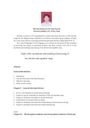
Problem B6 (Problem 4-194) Tuorial<br />
One ton <strong>of</strong> liquid water at 80oC is brought into a room. Determine the final<br />
equilibrium temperature in the room .<br />
Solution:<br />
Assumptions<br />
1. The room is well insulated and well sealed.<br />
2. The thermal properties <strong>of</strong> water and air are constant.<br />
3. Air is well-mixed.<br />
Properties<br />
The gas constant <strong>of</strong> air is R = 0.287kPa.m 3 /kg.K (Table A-1). The specific heat<br />
<strong>of</strong> water at room temperature is C = 4.18kJ/kg. o C (Table A-3).<br />
Analysis<br />
The volume and the mass <strong>of</strong> the air in the room are<br />
V = 4×5×6 = 120 m 3<br />
© Copyright 2005 Pr<strong>of</strong>. Arun S. Mujumdar.<br />
© Copyright 2005 Pr<strong>of</strong>. Arun S. Mujumdar.<br />
4m × 5m × 6m<br />
Room<br />
22 o C<br />
100kPa<br />
Water<br />
80 o C<br />
Heat<br />
ME2121 - <strong>First</strong> <strong>Law</strong> (ASM) 38
Solution to Problem B-6 (cont’d)<br />
Solution:<br />
3<br />
100kPa120m<br />
<br />
PV<br />
1 1<br />
m air<br />
<br />
141. 7kg<br />
RT<br />
1<br />
3<br />
0.287kPa<br />
m / kg<br />
K 295K<br />
<br />
Taking the contents <strong>of</strong> the room, including the water, as<br />
our system,<br />
Energy balance:<br />
So<br />
Or<br />
0 U<br />
Ein<br />
<br />
<br />
E<br />
<br />
out<br />
Net energy transfer by heat,<br />
work, and mass<br />
<br />
E<br />
<br />
<br />
system<br />
U<br />
water<br />
U<br />
air<br />
Change in internal, kinetic,<br />
Potential, etc. energies<br />
mCT<br />
T<br />
mC<br />
T<br />
T<br />
0<br />
2 1<br />
2 1<br />
<br />
water v<br />
air<br />
© Copyright 2005 Pr<strong>of</strong>. Arun S. Mujumdar.<br />
4m × 5m × 6m<br />
Room<br />
22 o C<br />
100kPa<br />
Water<br />
80 o C<br />
Heat<br />
ME2121 - <strong>First</strong> <strong>Law</strong> (ASM) 39
Solution to Problem B-6 (cont’d)<br />
Substituting,<br />
<br />
<br />
<br />
<br />
1000kg4.181kJ<br />
/ kg<br />
CT<br />
80 C 141.7kg0.718kJ<br />
/ kg<br />
CT<br />
22 C 0<br />
It gives<br />
T f<br />
78.6 C<br />
where<br />
T<br />
f<br />
f<br />
is the final equilibrium temperature in the room.<br />
Further discussion<br />
1. What if there are heat losses from the room?<br />
2. Initially dry air. What if air humidity effect is included?<br />
is then a function <strong>of</strong> humidity.<br />
3. Is room pressure affected by vaporization?<br />
4. What if we have 10 tons <strong>of</strong> water? Will it all vaporize?<br />
What is the humidity condition?<br />
© Copyright 2005 Pr<strong>of</strong>. Arun S. Mujumdar.<br />
4m × 5m × 6m<br />
Room<br />
22 o C<br />
100kPa<br />
Water<br />
80 o C<br />
Heat<br />
ME2121 - <strong>First</strong> <strong>Law</strong> (ASM) 40<br />
f