Condensing wall mounted Combination Boiler - Heatline
Condensing wall mounted Combination Boiler - Heatline
Condensing wall mounted Combination Boiler - Heatline

You also want an ePaper? Increase the reach of your titles
YUMPU automatically turns print PDFs into web optimized ePapers that Google loves.
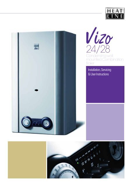
24/28<br />
Installation, Servicing<br />
& User Instructions<br />
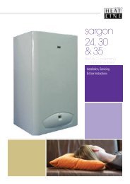
vizo 24/28<br />
<strong>Condensing</strong> <strong>wall</strong><br />
<strong>mounted</strong> <strong>Combination</strong><br />
<strong>Boiler</strong>
Natural Gas / LPG<br />
HEATLINE Vizo24 / Vizo28 <strong>Condensing</strong> <strong>Combination</strong> <strong>Boiler</strong>s<br />
British Gas Service Listing<br />
Vizo 24 <strong>Condensing</strong> <strong>Combination</strong> <strong>Boiler</strong> G.C.No 47-157-08<br />
Vizo 28 <strong>Condensing</strong> <strong>Combination</strong> <strong>Boiler</strong> G.C.No 47-157-09<br />
The HEATLINE range of heating boilers is manufactured from high quality materials, enabling reliability and<br />
optimum performance.<br />
HEATLINE is committed to the continual development of their appliances to ensure their customers benefit from the<br />
latest advances in combustion technology and energy savings.<br />
Type test for purpose of Regulation 5 certified by:<br />
Notified Body IMQ 51BP2727 CE Directives 90/396/EEC<br />
51BP2728DR CE Directives 92/42/EEC<br />
Product/Production certified by:<br />
Notified Body IMQ 51BP2727 CE Directives 90/396/EEC<br />
51BP2728DR CE Directives 92/42/EEC<br />
The manufacturer, in the continuous process to improve his products, reserves the right to modify the data expressed in<br />
the present documentation at any time and without prior notice.<br />
The present documentation is an informative support and it cannot be considered as a contract towards third parties.<br />
'Benchmark' Log Book<br />
As part of the industry-wide initiative the Vizo24/Vizo28 boilers come<br />
complete with an Installation, Commissioning and Service Record Log<br />
Book. Please read the Log book carefully and in accordance with current<br />
regulations complete all sections relevant to the appliance and<br />
installation. The details within the Log Book will be required in the event<br />
of any warranty work.<br />
On completion, the Log Book must be left with the end user and the<br />
relevant sections completed on each subsequent Service visit.<br />
vizo 24/28
Contents<br />
Section<br />
Page<br />
Preface 3<br />
1. Installation Regulations 3<br />
The Signs on Box 4<br />
The Signs on <strong>Boiler</strong> 4<br />
2. Technical Data 5<br />
3. <strong>Boiler</strong> Characteristics 7<br />
4. Operation 8<br />
5. General Installation 9<br />
6. Appliance Siting 11<br />
7. Flue Terminal Location 11<br />
8. General Flue Info 13<br />
9. Electrical Connections 14<br />
10. <strong>Boiler</strong> Installation 16<br />
11. Gas Supply 19<br />
12. Filling the System 19<br />
13. Control Panel Functions 19<br />
14. Commissioning 20<br />
15. Onboard Adjustments 21<br />
16. Safety Devices 22<br />
17. Routine Servicing 23<br />
18. Component Replacement 25<br />
19. Gas Type Conversion 32<br />
20. Fault Finding Chart 33<br />
Appendix<br />
Spare Parts List 37<br />
User Instructions 38<br />
vizo 24/28
03<br />
The <strong>Heatline</strong> gas fired, condensing combination boiler<br />
meets the requirements of regulations and is deemed to meet<br />
the requirements of:<br />
� Gas Appliance Directive 90/396/EEC<br />
� Efficiency Directive 92/42/EEC<br />
� Low Voltage Directive 73/23 EEC (modified from 93/68)<br />
� Electromagnetic Compatibility Directive 89/396 EEC<br />
(modified from 93/68)<br />
<strong>Heatline</strong> declares that the materials used in the<br />
manufacturer of this appliance are non-hazardous and that no<br />
substances harmful to health are contained within the<br />
appliance.<br />
The Vizo24 / Vizo28 must be installed in accordance with<br />
these instructions and the regulations currently in force.<br />
Read these instructions fully before installing or using the<br />
appliance.<br />
<strong>Heatline</strong> accepts no responsibility for unsatisfactory<br />
performance of the appliance or flue arising from the failure<br />
to comply with the installation instructions.<br />
If the boiler is sold or installed to another customer, all<br />
documents must be transferred from existing customer to the<br />
new one.<br />
Warnings<br />
Preface<br />
Heat Line accepts no responsibility for the unsatisfactory<br />
performance of the appliance or flue arising from the failure<br />
to comply with the installation and user instructions.<br />
Incorrect installation could invalidate your guarantee and<br />
may lead to prosecution.<br />
If the appliance is re-sold or installation transferred the<br />
appliance must be re-registered with <strong>Heatline</strong> in order to<br />
maintain the guarantee.<br />
The boiler must be installed in accordance with these<br />
instructions and the regulations currently in force. Read<br />
these instructions carefully before installing or using the<br />
appliance.<br />
1. Installation Regulations<br />
vizo 24/28<br />
1.1. This appliance must be installed in accordance with<br />
the Rules in Force by a registered C.O.R.G.I.<br />
engineer in accordance with the Gas Safety<br />
(Installation and Use) Regulations. Failure to install<br />
this appliance correctly may invalidate your<br />
guarantee and may lead to prosecution.<br />
1.2. Your C.O.R.G.I. registered engineer should carry a<br />
C.O.R.G.I. ID card containing their registration<br />
number, which should be recorded in your<br />
BENCHMARK Log Book, which is supplied with<br />
the Instructions. You can check the validity of this<br />
ID number by contacting C.O.R.G.I. on 0870 401<br />
2300.<br />
1.3. This appliance must be installed in accordance with<br />
the Gas Safety (Installation and Use) Regulations,<br />
current Building Regulations, Building Standards<br />
(Scotland), I.S.813 Installation of Gas Appliances<br />
(Ireland), IEE Wiring Regulations (BS 7671), Health<br />
and Safety Document No. 635 (Electricity at Work<br />
Regulations) and Local Water Authority Bye Laws.<br />
1.4. On installation the following British Standards must<br />
also be considered:<br />
o BS 6798 Specification for installation of gas fired<br />
hot water boilers of rated input not exceeding<br />
70kW.<br />
o BS 5449 Central heating for Domestic Premises.<br />
o BS 5546 Installation of gas hot water supplies for<br />
domestic purposes.<br />
o BS 5440 Flues and Ventilation for gas appliances<br />
of rated input not exceeding 70kW (Part 1 Flues)<br />
o BS 5440 Flues and Ventilation for gas appliances<br />
of rated input not exceeding 70kW (Part 2 Air<br />
Supply)<br />
o BS 6891 Installation of low pressure gas pipework<br />
installations up to 28mm (RI).<br />
1.5. Due to the manufacturer’s continuous improvement<br />
policy the manufacturer reserves the right to change<br />
any specification of the appliance or make<br />
modifications to these instructions, which meet<br />
current regulations at the time of print. However, the<br />
instructions must not be taken as overriding statutory<br />
requirements.<br />
1.6. To ensure reliability and continued performance<br />
ensure that other components in the system are also<br />
approved to relevant standards and that the appliance<br />
and system is adequately protected and maintained on<br />
an annual basis.<br />
For further information or advice contact <strong>Heatline</strong> TM<br />
Service & Technical Enquiries in UK on 0870 777 8318,<br />
Ireland on 01 466 4664 or E–mail via our web site<br />
www.heatline.co.uk.
04<br />
The Signs on Box<br />
The sign of approval the Vizo24 & Vizo28<br />
<strong>Boiler</strong>s have been certified by GASTEC<br />
Italy.<br />
This is a fragile piece of equipment: Do<br />
not drop.<br />
Avoid getting the box damp or wet.<br />
The packed appliances may be stacked five<br />
high.<br />
Do not crush the packaging as this may<br />
damage the appliance.<br />
.<br />
Store the appliance upright as indicated on<br />
the box.<br />
Handling This appliance is heavy, truck if possible<br />
and obtain assistance if required.<br />
To remove the appliance:<br />
1. Carefully slit or remove the sealing tape<br />
being careful not to scratch the appliance<br />
door.<br />
2. Fully open the carton lid and remove any<br />
instructions and componenets.<br />
3. Read the instructions carefully before<br />
installation of the appliance.<br />
4. Roll the carton onto its open face.<br />
5. Lift the carton free of the inner packaging.<br />
6. Remove the mounting bracket and valve<br />
package.<br />
7. Stand the boiler on its base within the<br />
styrene block and remove the top<br />
packaging piece.<br />
8. If you wish to remove the styrene base lie<br />
the appliance on its back to do so.<br />
The Signs on <strong>Boiler</strong><br />
vizo 24/28<br />
This picture shows the terminal block,<br />
which is located at the bottom left hand<br />
side of the control panel cover, to which a<br />
voltage free room thermostat may be<br />
fitted. NOTE: This is a voltage free<br />
connection and no power must be applied<br />
to these terminals. For mains powered thermostat<br />
connection, see section 9.5.<br />
Warning! High Voltage: This sign is<br />
located on the back of the control box<br />
housing warning of high voltages within<br />
the control box. Turn off and isolate the<br />
appliance before removing this cover.<br />
NOTE: Take care as there may be residual voltage<br />
within some components<br />
Potentiometer Cover: Removal of the<br />
cover, which is found on the back of the<br />
control box, gives access to the<br />
adjustment potentiometers. NOTE: Do<br />
not make any adjustments without<br />
reading the instructions carefully.
05<br />
2. Technical Data<br />
VIZO 24<br />
(24 kW)<br />
VIZO 28<br />
(28 kW)<br />
VIZO 24<br />
(24 kW)<br />
Heat Input (max) kW 25,7 28,5 Maximum heating temperature ºC 85 85<br />
Heat Output (max) kW 24,82 27,47<br />
Max. domestic hot water<br />
temperature<br />
Heat Input (min) kW 10,12 15 Operating pressure (Bar)<br />
Heat Output (min) kW 9,27 14,26<br />
Domestic water supply<br />
pressure (Bar)<br />
vizo 24/28<br />
VIZO 28<br />
(28 kW)<br />
ºC 64 64<br />
PMS<br />
Nominal<br />
(Min)<br />
PMS<br />
(Min)<br />
3<br />
1.5<br />
(0,8)<br />
8<br />
(0,25)<br />
Useful efficiency at 100%<br />
load<br />
% 96,6 96,4 Expansion Vessel Capacity Litres 7 7<br />
Useful efficiency at 30% load<br />
% 99.09 101<br />
Expansion Vessel<br />
Pre-charge Pressure<br />
bar 0,5 0,5<br />
Burner injector<br />
Burner Pressure<br />
(Natural Gas)<br />
Burner Pressure (Propane)<br />
mm.<br />
mbar<br />
1,23 NG<br />
0.76 LPG<br />
Max 12.7<br />
Min 2.0<br />
mbar Max 27,9<br />
Min 4,4<br />
1,20 NG<br />
0.76 LPG<br />
Domestic Water Supply<br />
Output at 35º C ∆T<br />
3<br />
1.5<br />
(0,8)<br />
8<br />
(0,25)<br />
L/min 9,92 11,3<br />
Max 11,6<br />
Min 3,5 Air Intake Pipe Diameter mm 100 100<br />
Max 27,7<br />
Min 6,1 Flue Pipe Diameter mm 60 60<br />
Power Supply Input 220-240V-50Hz Max. Flue Length (Horizontal) m<br />
Max. power consumption Watt 164 Max. Flue Length (Vertical) m<br />
Level of Protection IPX 4 D<br />
Equivalent Length 45 0 Bend<br />
Equivalent Length 90 0 Bend<br />
m<br />
2.5 60/100<br />
7.0 80/125<br />
3.0 60/100<br />
8.0 80/125<br />
1.0<br />
1.5<br />
2.5 60/100<br />
7.0 80/125<br />
3.0 60/100<br />
8.0 80/125<br />
Case Dimensions 24kW mm 330d x 405w x 720h Net weight Kg 37 38<br />
Case Dimensions 28kW mm 330d x 430w x 720h Gross Weight kg 40 41<br />
1.0<br />
1.5
06<br />
10<br />
19<br />
9<br />
20<br />
1<br />
18<br />
A B C D E<br />
Key<br />
1 - Fan<br />
2 - Air Pressure Switch<br />
3 - Fan Hood<br />
4 - Primary Heat Exchanger<br />
6<br />
3<br />
4<br />
16<br />
5<br />
8<br />
17<br />
7<br />
13<br />
23<br />
15<br />
14<br />
12<br />
11<br />
21<br />
2<br />
At Rear Side<br />
22<br />
At Rear Side<br />
5 - Combustion Chamber<br />
6 - Ignition Electrode<br />
7 - Flame Sensor Electrode<br />
8 - Burner<br />
9 - Overheat Safety Thermostat<br />
10 - Heating Sensor<br />
11 - Automatic Air Vent<br />
12 - Pump<br />
13 - Water Pressure Switch/Sensor<br />
14 - D.H.W. Flow Sensor<br />
15 – Heating Circuit– Pressure Safety Valve<br />
16 - Gas Valve<br />
17 - Secondary Heat Exchanger<br />
18 - Three-Port Valve Motor<br />
19 - D.H.W. Sensor<br />
20 - Three-Port Valve<br />
21 - Filter Valve ( Below the pump)<br />
22 - Expansion Vessel (At rear of the boiler)<br />
23 - <strong>Condensing</strong> Unit<br />
A - Heating Flow (22mm)<br />
B - D.H.W. Outlet (15mm)<br />
C - Gas Inlet (22mm)<br />
D - Cold Water Inlet (15mm)<br />
E - Heating Return (22mm)<br />
vizo 24/28
07<br />
3. <strong>Boiler</strong> Characteristics.<br />
3.1 The Vizo24 / Vizo28 is a fan flued, <strong>wall</strong>-<strong>mounted</strong><br />
condensing type combination boiler that supplies both<br />
central heating and mains fed domestic hot water.<br />
Being room sealed the boiler may be installed in any<br />
room or internal compartment without the need for<br />
purpose made ventilation. However, if the boiler is<br />
installed in a compartment it is recommended that the<br />
compartment is ventilated for cooling purposes. A<br />
functional diagram of the boiler’s principal<br />
components is given as figure 1.<br />
3.2 Range rated from 24kW to 28kW the Vizo24 /<br />
Vizo28 heat output can be focused to match the<br />
designed heating systems requirements by a simple<br />
adjustment.<br />
3.3 An electronic control unit, consisting of a PCB,<br />
which includes ignition module provides direct burner<br />
ignition and flame supervision along with continuous<br />
modulation of the burner’s gas supply.<br />
3.4 An interface unit, which includes boiler<br />
adjustment potentiometers and fault display provides<br />
easy service ability to the boiler.<br />
3.5 Heat transfer to the boiler’s primary hydraulic<br />
circuit is obtained via a primary, gas to water heat<br />
exchanger contained within a hermetically sealed<br />
combustion chamber. A 230 volt, single speed fan<br />
expels the products of combustion from the<br />
combustion chamber to outside air via an associated<br />
flue system. The fan is activated at the beginning of<br />
each ignition cycle and its operation monitored by<br />
means of negative and positive sensing points<br />
connected to an air pressure switch.<br />
3.6 A secondary heat exchanger allows the<br />
instantaneous transferral of heat from the primary<br />
hydraulic circuit to water destined for domestic hot<br />
water use. The secondary heat exchanger is sized so<br />
as to minimise thermal shock and is protected against<br />
the build up of lime scale by limiting the D.H.W.<br />
outlet water temperature to a maximum of 64°C.<br />
vizo 24/28<br />
3.7 An integral pump located in the boilers main<br />
hydraulic circuit circulates water through the primary<br />
heat exchanger to either the central heating circuit or<br />
D.H.W. heat exchanger, depending on the demand. In<br />
the event of reduced or interrupted water circulation<br />
in the central heating circuit, a system by-pass should<br />
be fitted as far away from the boiler as possible.<br />
Note: It is no longer permissible to utilise a nonthermostatic<br />
controlled radiator as a by-pass.<br />
3.8 Room temperature can be controlled by the use of<br />
an external room thermostat or temperature regulator.<br />
Note connection of the room thermostat is dependant<br />
on the operating voltage of the thermostat. See<br />
section 9.4 & 9.5 for details<br />
3.9 Using an outdoor temperature sensor, which can<br />
be connected directly to the main PCB, the boiler<br />
operating temperature can be automatically adjusted<br />
in line with outdoor climatic conditions.<br />
3.10 The boiler incorporates an integrated clock,<br />
which allows the setting of central heating periods<br />
and the boiler’s control panel incorporates an LCD<br />
display, which indicates the state of operation and<br />
fault defect codes.
08<br />
4. Operation<br />
4.1 Using the operating switch the boiler can be<br />
set to operate either on domestic hot water<br />
only or domestic hot water and heating.<br />
Note: Domestic hot water demand draws<br />
preference over heating. During heating periods<br />
the boiler will automatically revert back to heating<br />
mode, after a draw off of hot water, but there will<br />
be a 45sec delay if the No.3 dipswitch is set to the<br />
OFF position. See fig 19 page 21.<br />
4.2 Depending on demand water is either diverted via<br />
the three port valve to the secondary water-towater<br />
heat exchanger for domestic hot water or<br />
directly to the heating system. Schematic<br />
diagrams showing the flow within the boiler’s<br />
central heating hydraulic circuit figure 2a and<br />
D.H.W. hydraulic circuit figure 2b are given.<br />
4.3 DOMESTIC HOT WATER MODE:<br />
� On opening a hot water faucet the boiler<br />
automatically responds to fire the boiler and<br />
supply the water-to-water heat exchanger with hot<br />
water via the three port valve, located on the<br />
hydro-block. The boilers electronic control unit<br />
automatically modulate the burner’s output to<br />
maintain the required temperature at the faucet.<br />
Hot water will continue to flow until the faucet is<br />
closed and the boiler automatically shuts down.<br />
Note that the pump will continue to run for a<br />
further 10secs to dissipate the residual heat from<br />
the boiler.<br />
4.4 DOMESTIC HOT WATER AND CENTRAL<br />
HEATING MODE:<br />
� When heating demand is requested, power is on<br />
and the timer and thermostat are calling for heat,<br />
the boiler will fire automatically. An integral<br />
pump is then energised and hot water from the<br />
boilers primary circuit is circulated around the<br />
central heating systems pipe-work and radiators.<br />
When the demand for central heating is no longer<br />
present, either the thermostat reaches temperature<br />
or the time clock reaches the end of its set period,<br />
the burner will shut down and the boiler will<br />
revert to stand-by, waiting to respond to the next<br />
heating or hot water demand. The pump will<br />
continue to operate for a short period of time to<br />
dissipate any excess heat from within the boiler’s<br />
heat-exchanger. If during the heating period there<br />
is a call for hot water this will take preference<br />
over heating. When satisfied the boiler will then<br />
supply the heating demand as required. Note<br />
there may be a 45sec delay depending on how the<br />
boilers dipswitches are set. See section 15.4 for<br />
details.<br />
Figure 2a<br />
Figure 2b<br />
vizo 24/28<br />
Figure
09<br />
5. General Installation<br />
5.1 Installer Testing & Commissioning Tips<br />
• The installer shall instruct the user in the operation<br />
of the boiler, safety devices contained within the<br />
boiler and instruction on how to re-pressurise the<br />
system if the water pressure falls. The installer<br />
should then hand over the instructions with the<br />
Benchmark Logbook that has been completed.<br />
• The user should be instructed to keep the<br />
instructions in a safe place for servicing and future<br />
reference.<br />
• It is important to keep the boiler clear of dust<br />
during the installation. In particular, do not allow<br />
debris to enter the top of the boiler where the flue<br />
connection is made. This may cause the fan outlet<br />
to get blocked or combustion chamber to fill with<br />
debris and will, of course, cause the boiler to fail to<br />
ignite on first ignition. It is recommended that you<br />
check the fan outlet before you light the boiler.<br />
• Before you fit the boiler ensure that the pipe work<br />
that you are installing is connected to the<br />
appropriate connections on the boiler i.e. cold<br />
water pipe to cold water inlet, hot water outlet to<br />
the hot water tap etc.<br />
• Because the boiler is actually operated, at the end<br />
of each production stage, a small amount of water<br />
is retained within the boiler when packed. Please<br />
ensure that you spin the pump rotor manually<br />
before firing the boiler.<br />
• It is important that the boiler must be used in<br />
conjunction with a Heat Line approved flue and all<br />
flue connections are correctly sealed.<br />
• Remember to flush out the system, both cold and<br />
hot, in order to remove the debris from the system.<br />
This should be done particularly where boilers are<br />
being fitted to existing radiator circuits.<br />
• Refer to BS 7593:1992 for the details to clean<br />
DHW and Central heating system.<br />
• This boiler has been factory set and does not<br />
require any adjustments to the gas valve or fan<br />
speed.<br />
• Remember to release the small cap on top of the<br />
auto air purge device on the pump, 1 turn, before<br />
filling. This will ensure that air is removed as the<br />
system fills.<br />
• Do not use the pressure relief valve as a means<br />
of flushing the system, please use the valve below<br />
the pump. Discharging water from the system from<br />
the pressure relief valve may allow water to seep<br />
after you have left the job, causing the boiler to<br />
lose pressure and debris to collect on the seating.<br />
• The boiler is fitted with inlet filters both on the<br />
cold water inlet and the central heating return. If<br />
you are unable to obtain hot water at the faucet it is<br />
likely that the cold water inlet valve filter has<br />
become blocked, whilst blockage of the filter on<br />
vizo 24/28<br />
central heating return valve will cause the heater to<br />
lock out at the overheat thermostat as the water<br />
flow is reduced.<br />
• If you are able to obtain hot water but not heating<br />
it is also advisable to check the clock connections<br />
and that the room thermostat and time clock are<br />
calling for heat.<br />
• Remember that after hot water draw off there is a<br />
45 sec delay before the heating will fire up if No.3<br />
dipswitch is in the OFF position, see fig 19 on<br />
page 21<br />
• When commissioning the boiler check the inlet<br />
pressure is at 20mbar and burner pressure against<br />
the Technical data on page 5.<br />
• Note an anti-cycle delay time can be set up to a<br />
maximum of 255 seconds by adjusting<br />
potentiometer 2 as described in section 15.5 on<br />
page 21.<br />
If you experience any problems please refer to the<br />
installation and commissioning guidelines within the<br />
boiler instruction manual. If necessary, please contact<br />
Heat Line TM Service Enquiries, in the UK, for further<br />
advice and assistance on 0870 777 8318, in Ireland<br />
call 01 466 4664.<br />
NOTE – FOR INSTALLERS:<br />
REMEMBER IT IS A LEGAL REQUIREMENT<br />
TO COMPLETE THE BENCHMARK CODE OF<br />
PRACTICE LOGBOOK BEFORE LEAVING<br />
THE INSTALLATION.
10<br />
5.2 The boiler is designed to operate on fully pumped,<br />
pressurised sealed systems operating at a maximum of<br />
3bar pressure and maximum design flow temperature of<br />
85 0 C.<br />
5.3 The boiler’s integral expansion vessel is pre-charged to<br />
a pressure of 0.5bar and will accommodate a system<br />
volume of 125 l. at an average water temperature of 75 0 C<br />
and maximum system pressure of 3 bar. If the system<br />
volume is more than 125 l. an additional expansion vessel<br />
must be fitted to suit the size of the system. A typical<br />
installation of an additional pressure vessel is shown<br />
below in figure 3 below.<br />
Domestic hot water<br />
Heating outlet<br />
Figure 3.<br />
Flow<br />
control<br />
valve<br />
<strong>Boiler</strong><br />
Bypass<br />
valve<br />
Flow<br />
control<br />
valve<br />
Heating return<br />
Flow<br />
control<br />
valve<br />
Filling<br />
device<br />
Cold water<br />
supply<br />
Additional<br />
expansion<br />
vessel (if<br />
required)<br />
5.4 The heating circuit should be designed and balanced to<br />
give a 20 0 C temperature rise across the boiler flow and<br />
return.<br />
5.5 When fitting a new boiler to an existing system the<br />
system must be thoroughly flushed in accordance with the<br />
recommendations of BS7593 prior to installation.<br />
5.6 It is recommended that the system should be protected<br />
by an anticorrosion inhibitor. Failure to comply with this<br />
requirement may invalidate your guarantee.<br />
5.7 On installation it is important to ensure that the heat<br />
exchanger is not a natural collecting point for air and<br />
where possible, the system pipe work should have a<br />
gradient to ensure any excess air is carried naturally to<br />
other purpose made, air release points.<br />
5.9 In high water volume systems or under floor heating<br />
systems where prolonged operation of the boiler is<br />
expected at temperatures below 60 0 C, a by-pass must be<br />
vizo 24/28<br />
installed on the boiler outlet in order to prevent<br />
condensation forming inside the combustion chamber.<br />
Failure to comply with this requirement will invalidate the<br />
manufacturer’s guarantee.<br />
5.10 The pressure relief discharge must be directed away<br />
from any electrical equipment or where it could cause a<br />
hazardous situation.<br />
5.11 To enable adequate drainage of the system drain<br />
cocks compliant with BS2879 must be fitted at the lowest<br />
points in the system pipe-work.<br />
5.12 To obtain the best hot water performance from your<br />
boiler it is suggested that the cold water supply to the<br />
boiler is the first draw off from the incoming mains<br />
supply. Note that the boiler will not operate unless there is<br />
a minimum pressure of 0.25bar with a flow rate of<br />
2.5l/min. Where inlet pressures exceed 8bar, a pressure<br />
regulator must be fitted to the cold water supply.<br />
5.13 Where cold water mains are fitted with a water meter,<br />
check valve(s) or loose jumper stopcock, a domestic hot<br />
water mini-expansion vessel may need to be fitted.<br />
5.14 Although the boiler is designed to inhibit the<br />
formation of scale, in hard water areas above 200mg/l, a<br />
proprietary scale reduced should be fitted in the cold water<br />
supply to the boiler. Failure to comply may invalidate<br />
your guarantee.<br />
5.15 To obtain the best hot water performance from your<br />
boiler it is suggested that supplies to faucets are run in<br />
15mm copper, as short as possible and where practical, be<br />
insulated to reduce heat loss.<br />
5.16 The boiler incorporates a frost protection thermostat.<br />
Therefore if the boiler will not be used for long periods of<br />
time during cold weather, in order to avoid freezing the<br />
electric supply must be left ON and all the central heating<br />
isolation valves must be left open. The internal frost<br />
thermostat will then operate the boiler if the temperature<br />
falls too low. However, if the electrical supply is to be<br />
turned off the boiler, the heating system and domestic hot<br />
water circuit must be drained.
11<br />
6. Appliance Siting<br />
6.1 If the boiler is to be installed in any room or<br />
compartment, it requires no purpose made ventilation for<br />
combustion air. If sited in a room containing a bath or<br />
shower then particular reference is drawn to the current<br />
I.E.E. Wiring Regulations and local Building Regulations.<br />
6.2 If the Vizo24 / Vizo28 boiler is installed in a<br />
compartment there must be purpose made ventilation for<br />
cooling purposes.<br />
6.3 The boiler is not suitable for external installation<br />
unless protected by a purpose made building such as a<br />
boiler house.<br />
6.4 The following clearances are recommended for<br />
installation purposes; 200mm above, 300mm below and<br />
50mm at each side. 600mm is required at the front but this<br />
may be upon opening a cupboard door.<br />
6.5 The boiler must be sited at least 1m away from<br />
flammable materials and heat sensitive <strong>wall</strong>s must be<br />
protected by appropriate insulation.<br />
6.6 The <strong>wall</strong> on which the boiler is <strong>mounted</strong> must be<br />
sufficiently strong enough to support the weight of the<br />
boiler.<br />
6.7 A condensate drain pipe must be fitted to allow<br />
discharge of condensate to a drain or soakway.<br />
Where possible condensate should be discharged into the<br />
household internal drainage system. If this is not practical,<br />
discharge can be made into an external drain. If neither of<br />
the above options are possible then condensate must be<br />
discharged into a purpose designed soakway.<br />
o It is recommended that any external condensate<br />
pipe is insulated and increased to 32mm diameter<br />
in order to prevent the condensate from freezing.<br />
o To avoid excessive condensation occurring within<br />
the boiler flue the boiler should wherever possible,<br />
be sited to ensure the shortest possible flue run is<br />
utilised.<br />
6.8 For compartment installation the requirements of<br />
BS6798 and BS5440: Part 2 must be met.<br />
� The compartment must be of sufficient size to permit<br />
access for inspection and servicing or the removal of<br />
the boiler and any ancillary equipment.<br />
� Any space used for airing clothes or storage must be<br />
separated from the appliance by a non-combustible<br />
partition. Where the partition is formed from<br />
perforated material, then the major dimension of the<br />
apertures shall not exceed 13mm.<br />
� No combustible surface must be within 20mm of the<br />
boiler casing without protection.<br />
� There must be 20mm clearance between the<br />
compartment door and boiler case.<br />
vizo 24/28<br />
� Where the boiler’s flue pipe passes through the airing<br />
space, it must be protected by a non-combustible<br />
sleeve or fire stop which has a minimum clearance of<br />
20 mm from the flue pipe. In addition, if the flue pipe<br />
passes through the partition then the clearance gap of<br />
the flue pipe or its guard with the partition must not<br />
exceed 13 mm.<br />
6.9 When the boiler is intended for use with LPG it must<br />
not be installed in a room or internal space below ground<br />
level..<br />
7. Flue Terminal Location<br />
6.<br />
7.1 The flue terminal must be sited with minimum<br />
clearances as specified in Figure 4. Note if pluming<br />
becomes problematic or causes a nuisance a plume<br />
management kit is available from your stockist.<br />
.<br />
7.2 Current regulations and standards require a<br />
terminal guard to be fitted where the terminal is<br />
accessible to touch or at risk of being damaged. All<br />
<strong>wall</strong> <strong>mounted</strong> terminals sited within 2m of the level<br />
which people have normal access, should be<br />
adequately protected with a suitably sited guard<br />
7.3 Where the flue terminates within 1m of a plastic<br />
or painted gutter or within 500mm of painted eaves<br />
then protection should be provided in the form of an<br />
aluminium shield at least 1m in length, fitted to the<br />
underside of the gutter or painted surface.<br />
7.4 The flue should not be sited where the condensate<br />
“plume” may give rise to a nuisance factor under<br />
certain weather conditions.<br />
NOTE: If you have difficulty siting the flue in an<br />
appropriate location your supplier will be happy to<br />
supply a “anti-plume management kit”, which<br />
discharges the flue products at a higher level.
12<br />
TERMINAL POSITION MINIMUM<br />
DISTANCE<br />
A- Directly below an openable window or other opening e.g. air brick 300 mm<br />
B- Below gutters, soil pipes or drain pipes 75 mm<br />
C- Below eaves 200 mm<br />
D- Below balconies or car front roofs 200 mm<br />
E- From vertical drain pipes and soil pipes 150 mm<br />
F- From internal or external corners 300 mm<br />
G- Above ground, roof or balcony level 300 mm<br />
H- From a surface facing a terminal 600 mm<br />
I- From a terminal discharging towards another terminal 1200 mm<br />
J- From an opening in a car port (e.g. door, window) into a dwelling 1200 mm<br />
K- Vertically from a terminal on the same <strong>wall</strong> 1500 mm<br />
L- Horizontally from a terminal on the same <strong>wall</strong> 300 mm<br />
M- Above an opening, air brick, opening windows, etc. 300 mm<br />
N- Horizontally to an opening, air brick, opening windows, etc. 300 mm<br />
P- Above roof level (to base of terminal) 300 mm<br />
Q- From adjacent <strong>wall</strong> to flue 300 mm<br />
R- From an adjacent opening window 1000 mm<br />
S- From another roof terminal 600 mm<br />
Internal Corner External Corner<br />
Figure 4<br />
Double Corners<br />
vizo 24/28
13<br />
8. General Flue Info<br />
8.1 The boiler utilises a concentric flue arrangement<br />
which consists of a 60mm-diameter inner flue and<br />
100mm-diameter outer air inlet duct.<br />
8.2. A standard 700+/-5mm flue kit (figure 5) is<br />
supplied with the boiler, which can be routed to the<br />
rear, left or right of the appliance by means of a 90 0<br />
degree bend. The bend is connected to the boiler<br />
using the screws provided and sealed with the gasket.<br />
Fig.5<br />
8.3. The 60/100cm flue pipes may be extended up to a<br />
maximum of 2.5m using additional spare components<br />
available from your supplier. This length can be<br />
increased to 7m using the 80/125mm flue kit.<br />
8.4. A vertical 60/100cm flue kit is also available<br />
from your supplier up to a maximum length of 3m.<br />
The terminal is suitable for a flat or pitched roof.<br />
This length can be increased to 8m using the<br />
80/125mm flue kit.<br />
8.5. The flue restrictor, as shown in figure 6, supplied<br />
with this boiler is NOT required.<br />
Figure 6a<br />
vizo 24/28<br />
8.6. The connection of vertical flue system is similar<br />
to the Horizontal flue connection. The flue is<br />
connected to the boiler via connection screws whilst<br />
the sections are held together with the clamps<br />
provided.<br />
8.7. To avoid condensate dripping from the terminal<br />
the flue should be installed with an upward gradient<br />
(from the boiler) of 3 0 .<br />
Note. For each additional 90º elbow used the<br />
maximum flue length must be reduced by 1.5 m,<br />
whilst the use of 2 x 45º bends warrants a reduction<br />
of 2m.<br />
.<br />
WARNING!<br />
ONLY A HEATLINE APPROVED FLUE IS<br />
TO BE USED WITH THIS PRODUCT.<br />
FAILURE TO COMPLY WITH THIS<br />
REQUIREMENT WILL INVALIDATE YOUR<br />
GUARANTEE AND COULD LEAD TO<br />
PROSECUTION.
14<br />
9. Electrical Connections<br />
9.1 The boiler is supplied factory wired complete with<br />
1.5 m of mains fly lead. All electrical connections to<br />
the mains supply must be made in full accordance<br />
with the current I.E.E. regulations.<br />
9.2 The boiler must be connected to an effective earth<br />
system. Using the cable supplied the boiler may be<br />
connected via a 3 amp fused three pin plug to an<br />
unswitched shuttered socket outlet. However if the<br />
boiler is installed in a room containing a bath or<br />
shower regulations dictate that disconnection must be<br />
incorporated in the fixed wiring with a switch<br />
provided for disconnection from the mains supply<br />
having a contact separation of at least 3 mm on all<br />
poles and fused at 3 amp.<br />
9.3 The point of connection must be readily<br />
accessible, at a distance no further than 1.5m adjacent<br />
to the appliance and provide complete electrical<br />
isolation for the boiler and control system.<br />
9.4 The low voltage room thermostat terminal block<br />
is located to behind of left side of the plastic cover<br />
(figure 7). On connection of a voltage free room<br />
thermostat to the boiler, the factory fitted bridge<br />
across the room thermostat terminal connectors must<br />
be removed. If a mains voltage thermostat is to be<br />
used the please refer to figure 8.<br />
9.5 Mains powered thermostats must be connected<br />
directly to the mains circuit board as indicated in<br />
Figure 8. Cut the existing link and connect the wires<br />
into the thermostat circuit.<br />
9.6 Ensure that the polarity of the mains connection is<br />
correct as reversed polarity may cause the appliance<br />
to malfunction.<br />
9.7 While the boiler's main pcb, pump, three-way<br />
valve and gas valve are supplied at 230V AC., all<br />
other components and associated circuits are supplied<br />
at low voltage.<br />
9.8 On connecting the mains electrical supply to the<br />
boiler, it is essential to ensure that electrical safety<br />
checks for earth continuity, earth resistance, polarity<br />
and short circuit are carried out prior to making the<br />
vizo 24/28<br />
final connection. A diagram of the boiler's electrical<br />
circuit is given as figure 9.<br />
9.9 Fuse Ratings<br />
Bertelli & Partners Circuit Board<br />
F1 – 3.15amp fast blow<br />
F2 – 2amp fast blow<br />
SIT Circuit Board<br />
F1 – 2amp fast blow<br />
F2 – 2amp fast blow<br />
Figure 7<br />
Figure 8<br />
Warning: On no account must any external<br />
voltage be applied to any of the terminals on the<br />
heating control connection plug.<br />
F
15<br />
vizo 24/28
16<br />
Important Note.<br />
Connection to the mains electrical supply must<br />
be maintained at all times in order to provide<br />
domestic hot water, frost protection and pump<br />
over-run facility. Ensure that the boilers<br />
electrical supply is not interrupted by any<br />
external controls.<br />
10. <strong>Boiler</strong> Installation<br />
10.1 Prior to installing the boiler check the contents<br />
of the carton: Appliance, Valves (Fixing Jig<br />
Optional), Wall Hanging Bracket, Mounting<br />
Template Service, Installation and User Manual,<br />
Guarantee Card and Benchmark Log Book. The<br />
boiler dimensions are given in figure 10.<br />
10.2 Ensure that the boiler is suitable for the gas<br />
supply by checking the data plate, which is situated<br />
on the inside of the control panel door, and that the<br />
system and chosen boiler position is in accordance to<br />
Sections 5, 6 and 7 of these instructions.<br />
Dimension Vizo24 Vizo28<br />
A 405 430<br />
B 169 169<br />
C 60/100 60/100<br />
F 39 64<br />
G 64 64<br />
Figure 11<br />
TOP<br />
BOTTOM<br />
Figure 10<br />
vizo 24/28
17<br />
10.3 Position the supplied template on the <strong>wall</strong>,<br />
ensuring it is level both vertically and horizontally<br />
(figure 11). Mark the boiler fixing jig (if required),<br />
<strong>wall</strong> bracket fixing positions and flue outlet position<br />
(rear flue only). For flue side exit from the boiler -<br />
Mark the horizontal flue centre line on the rear <strong>wall</strong>.<br />
Extend the horizontal line to the side <strong>wall</strong> allowing a<br />
3 0 decline back towards the boiler, to enable<br />
condensate to drain back through the boiler. Mark the<br />
flue centre vertical line. ( figure 12.)<br />
Figure 12.<br />
10.4 When cutting the flue hole it is recommended<br />
that a 105mm diameter core drill is used where both<br />
internal and external access for the flue installation is<br />
available. Where only internal access is available a<br />
125mm diameter core drill should be used. (Note:<br />
Please take adequate precautions to prevent debris<br />
entering the boiler via the flue outlet).<br />
10.5 Using a 8·5mm drill bit, drill the holes for fixing<br />
jig (optional) and hanging bracket. Locate and secure<br />
the supplied <strong>wall</strong> mounting bracket and fixing jig in<br />
position (figure 13).<br />
10.6 Mount the boiler figure onto the 13fixing<br />
bracket via the boiler<br />
mounting slots, (figure 13).<br />
10.7 Connect isolation valves assembled (on the fixing jig, if<br />
used) to the boiler ensuring the washers are fitted correctly.<br />
10.8 On installing the flue, determine the required length of<br />
the outer air duct by measuring the distance 'L' (figure<br />
14b) from the face of the external <strong>wall</strong> to the back of<br />
boiler's elbow connecting collar. The measurement for the<br />
inner flue duct will be 'L' + 20mm<br />
10.9 Measuring from the back of the terminal connection,<br />
mark distance 'L' onto the outer air duct. (figure 14a)<br />
10.10 Cut the outer air duct only to the required length<br />
ensuring that the cut is square and free from burrs.<br />
figure 14a<br />
figure 14b<br />
vizo 24/28<br />
10.11 Measuring from the back of the terminal connection, mark<br />
distance 'L' + 20mm (figure 14) onto the inner flue duct and cut<br />
the duct to size, ensuring that the cut is square and free from<br />
burrs.<br />
10.12 Pass the flue assembly through the <strong>wall</strong> and connect the<br />
assembly to the boiler, ensuring that both the air and flue duct<br />
joints are fully pushed home into the connecting elbow's collar.<br />
10.13 With the flue and joints secured fit the flue trim to the<br />
external <strong>wall</strong> surface using a suitable mastic. Note. Where<br />
internal access only is available, the flue trim must be attached<br />
to the flue assembly prior to passing the assembly through the<br />
<strong>wall</strong>.<br />
10.14 For maximum flue lengths refer to the Technical Data on<br />
page 5 in this manual<br />
10.15 <strong>Condensing</strong> type boilers must be connected to the<br />
drainage system. A plastic drain must be fitted to allow<br />
discharge of condensate to a drain.<br />
Condensate should, if possible, be discharged into the internal<br />
household draining system. If this is not practical, discharge can<br />
be made externally into the household drainage system or a<br />
purpose designed soak away. Note if a soakway is used the<br />
drain must terminate at least 500mm from the external <strong>wall</strong>.
18<br />
10.16 Extract the bottom part of condensate trap , by<br />
turning anti-clockwise and fill it with approximately<br />
50 cc water re-connecting it to the boiler. (Figure b).<br />
10.17 Connect the condensate drainage pipe to the<br />
drainage system. (Figure a) Note due to the acidic<br />
nature of the condensate the drainage system must be<br />
made of non-corrosive material such as plastic tubing.<br />
10.18 Connect the domestic hot water, cold water<br />
inlet, heating system flow & return and pressure relief<br />
valve pipework to the boiler fittings, ensuring that the<br />
pipework has been correctly flushed before final<br />
connection.<br />
10.19 The electrical connections to the boiler must be<br />
in accordance to Section 9 of these instructions.<br />
NOTE: Place the filling loop in a visible<br />
accessible position and instruct the user how to<br />
pressurise the system if there is a fall in<br />
pressure.<br />
vizo 24/28
19<br />
11. Gas Supply<br />
11.1 The gas supply pipe must be capable of supplying the<br />
quantity of gas required by the boiler (see Technical Data, section<br />
2, page 5) in addition to the demand of any other gas appliances<br />
being serviced from that supply.<br />
11.2 The internal diameter of the gas supply from the meter to<br />
the boiler's gas inlet connection must not be less than 22mm.<br />
11.3 The meter governor must be capable of delivering a<br />
pressure of 20mbar (for natural gas).<br />
11.4 On final connection of the gas supply to the boiler, the<br />
complete gas installation including the gas meter, must be tested<br />
for soundness and purged.<br />
12. Filling the System<br />
12.1 The boiler must not be operated without water.<br />
12.2 On completion of the boiler installation and ensuring that<br />
all water connections are correctly made the boiler may be filled<br />
with water via the filling loop (not supplied with the boiler).<br />
Ensure that two manual feed valves and boiler isolation valves<br />
are open.<br />
12.3 Release the cover cap of the boiler's automatic air vent<br />
situated on top of the pump. (Figure 15)<br />
12.4 The manual feed valves must be closed and the filling loop<br />
disconnected once the pressure sensor, sited on the boiler’s<br />
control panel, indicates a system pressure between 1.0 and 1.5<br />
bar. Figure 15<br />
Release cover<br />
cap when filling<br />
system<br />
12.5 Check that all the water connections throughout the system<br />
are sound and bleed each of the heating system’s radiators in<br />
turn. As air is vented the system pressure may need topping back<br />
up to 1.0bar.<br />
12.6 Air must be vented from the boiler's pump by unscrewing<br />
the pump’s integral vent plug and allowing water to bleed for a<br />
few seconds. Take care not to allow water to splash onto any<br />
electrical components.<br />
12.7 When the system is bled of any air it must be re-filled until<br />
the pressure shown on the display gauge indicates a system<br />
pressure of 1.5bar.<br />
12.8 If the pressure exceeds 1.5 bar discharge the excess<br />
pressure from the system via a radiator valve or pipe connection.<br />
vizo 24/28<br />
Do not use the safety discharge valve as the valve seat may<br />
become contaminated with debris and fail to re-seal.<br />
Important Note.<br />
In order to maintain the appliance’s<br />
warranty; after initial filling the heating<br />
system must be thoroughly flushed using a<br />
propriety cleanser to remove foreign material<br />
and contaminants.<br />
13. Control Panel Functions<br />
1- D.H.W. temperature control 4- Function switch<br />
2- C/heating temperature control 5- Timer<br />
3- System pressure gauge 6- LED Display<br />
13.1 C/heating and D.H.W. temperature controls: The<br />
boiler's integral control unit monitors and adjusts both the<br />
boiler’s hydraulic circuit and D.H.W. water outlet<br />
temperatures by means of sensors located on the C/heating<br />
and D.H.W. flow outlets. The sensors electrical resistance,<br />
which is dependant on temperature, determines the current<br />
passing through the control potentiometers located on the<br />
control panel. The respective potentiometer control dial<br />
allows manual setting of the maximum required temperature<br />
(reference value) being between 30º and 85ºC for C/heating<br />
and 35º and 64ºC for D.H.W. When the boiler operates in<br />
heating or D.H.W. mode, the current received is compared<br />
to the manually set reference value. The difference of the<br />
two values operates the modulation of the gas valve<br />
adjusting the useful heat output generated and stabilising the<br />
temperature to within ±1ºC.
20<br />
13.2 Re-set function: Should the boiler lock out at<br />
any time, please check the gas supply and ionisation<br />
probe position, the boiler may be re-started by<br />
switching to standby “O” position (Switch 4 figure 16)<br />
waiting 15-30 seconds and switching back to its<br />
previous position once the fault has been eliminated.<br />
13.3 Function switch: The three position switch<br />
allows the boilers operation to be set to 'Stand-by’<br />
(centre position), ‘Heating + D.H.W.’ (left hand<br />
position) or ‘D.H.W. only’ (right hand position)<br />
14. Commissioning<br />
Figure 17<br />
14.1 The Vizo 24 & 28 boilers have been tested and preset<br />
at the factory and is dispatched with its on board<br />
controls set to provide a maximum central heating and<br />
D.H.W. output. Consequently, once all the connections<br />
have been made and the boiler has been filled with water<br />
to the designed system operating pressure, the boiler may<br />
be fired prior to adjusting it’s on board parameters to<br />
match the heating systems requirements.<br />
14.2 Prior to firing, check that the electrical supply to the<br />
boiler is 'On' (The green boiler ‘Stand by’ indicator will<br />
light) and the gas service cock is in the open position.<br />
� Set the boiler's central heating and domestic hot water<br />
temperature controls to maximum by turning them<br />
fully clockwise.<br />
� Set the external room thermostat (if fitted) to<br />
maximum and open the thermostatic radiator valves to<br />
maximum.<br />
14.3 Switch the boilers function switch to the central<br />
heating and domestic hot water position. The boiler's<br />
control unit will now automatically carry out preignition<br />
safety checks before igniting the burner.<br />
vizo 24/28<br />
14.4 During the 10 second burner ignition<br />
attempt visually check that all of the burner blades<br />
ignite correctly.<br />
If necessary, adjustments to the ignition rate may<br />
be made using potentiometer P4. Turning P4<br />
clockwise increases the ignition rate and anticlockwise<br />
decreases the rate. After successful<br />
ignition check the integrity of the boiler's flue<br />
for soundness and correct operation.<br />
14.5 Check the boiler for correct domestic hot water<br />
operation by opening and closing the household<br />
domestic hot water draw off taps.<br />
14.6 In order to maintain the appliance warranty after<br />
initial filling the heating system must be thoroughly<br />
flushed using a propriety cleanser to remove foreign<br />
material and contaminants.<br />
14.7 Restart the boiler and again allow the central<br />
heating system to reach maximum operating<br />
temperature. Check that all the water connections<br />
throughout the system are sound and bleed each of the<br />
heating systems radiators and purpose made air<br />
release points in turn.<br />
14.8 Check the system pressure and top up if<br />
necessary.<br />
14.9 Reset the central heating & domestic hot water<br />
temperature controls and room thermostat to the<br />
desired temperature settings.<br />
Important Notice.<br />
• Failure to thoroughly power flush the boiler and<br />
heating system or to add an anti corrosion<br />
inhibitor to the system water will invalidate the<br />
boiler's warranty.<br />
• The condensate trap must be filled with water<br />
and plastic discharge pipe connected to drain<br />
before operating the boiler.
21<br />
15. Onboard Adjustments<br />
15.1 The boiler incorporates 4 potentiometers and a<br />
bank of dip switches to allow adjustment to its pre-set<br />
parameters. These are situated on the rear of the<br />
control panel. (figure 18)<br />
The potentiometers can easily be accessed by<br />
removing the cover on the rear of control panel<br />
(Figure 19). However, to reach the dip switches, the<br />
control panel must be opened.<br />
POTENTIOMETERS<br />
P7<br />
P5<br />
P4<br />
P2<br />
Figure 18<br />
Potentiometer<br />
adjustment cover<br />
DIP SWITCHES<br />
Figure 19<br />
15.2 Setting the maximum c/heating flow<br />
temperature: The boiler is dispatched with a<br />
vizo 24/28<br />
maximum flow temperature factory set to 90°C.<br />
Where a lower maximum temperature is required<br />
such as in the case of under-floor heating, the factory<br />
setting can be altered between a maximum of 50°C<br />
and a minimum of 30ºC, by fitting dip switch '6' into<br />
ON position.<br />
15.3 Setting the boiler's integral pump: The boiler's<br />
integral pump is factory set to operate in both central<br />
heating and D.H.W. mode. Where an external pump<br />
is incorporated into the system design the integral<br />
pump may be disconnected in central heating mode<br />
by fitting dip switch '5' into the ON position.<br />
15.4 Setting the 45 seconds delay: The boiler is<br />
factory set to exclude the delay of 45 seconds before<br />
re-ignition between the closing of a hot water tap and<br />
CH start-up. This delay can be set to 45 seconds by<br />
setting dip switch ‘3’ (figure 19) into the OFF<br />
position.<br />
15.5 255 seconds delay setting: The boiler is capable<br />
of up to 255 seconds ignition delay (anti cycling time)<br />
before re-ignition following burner shut down on the<br />
primary hydraulic water reaching its set temperature.<br />
This delay can be increased up to a maximum of 255<br />
seconds by turning potentiometer P5 (Figure 19)<br />
clockwise.<br />
15.6 Pump working mode setting: The boiler is<br />
factory set to operate the pump for a period of 45sec<br />
before and after a heating cycle. This delay can be<br />
cancelled by setting dipswitch ‘2’ (figure 19) to the<br />
ON position. However, this is not recommended as<br />
the boiler over-heat thermostat may trip out, causing<br />
lock-out of the boiler.<br />
15.7 Setting the Heating output: The Vizo 24 & 28<br />
boilers are factory set to give maximum c/heating<br />
output. The maximum and minimum heat output for<br />
heating and domestic hot water may be adjusted, if<br />
required, using potentiometers P2 & P4 (figure 19).
22<br />
15.8 Gas valve ignition capacity. The graduated<br />
opening of the gas valve for ignition rate is governed<br />
by the 1 st potentiometer P7 control, which is factory<br />
set. To assist in setting the boiler's modulating gas<br />
rate parameters the ignition rate of the valve can be<br />
forced from minimum to maximum rate by setting the<br />
potentiometer clockwise.<br />
Important.<br />
Gas Type Dip Switch Positioning, Dip Switch 1,<br />
Dip Switch 4 and Dip Switch 5 is factory set and<br />
must not be adjusted.<br />
Figure 20<br />
15.9 The boilers integral pump is factory set to its<br />
maximum speed setting to give a 1000 l/hr flow on a<br />
nominal 4m head. The pump may be adjusted to a<br />
lower speed to match the designed c/heating system<br />
requirements. (figure 20)<br />
16. Safety Devices<br />
16.1 A hydraulically operated primary pressure sensor<br />
monitors water pressure or water shortage in the<br />
primary hydraulic circuit and will switch the boiler<br />
vizo 24/28<br />
off if the pressure is below 0.3bar. The boiler will not<br />
operate until the circuit has been re-pressurised.<br />
16.2 The temperature of the water flowing from the<br />
primary heat exchanger is monitored by an overheat<br />
thermostat located on the outlet pipe. If the water<br />
temperature gets too hot the switch opens, cutting off<br />
the electrical supply to the gas valve and causing the<br />
boiler to ‘Lock-out’. Once activated the boiler has to<br />
be manually re-set by switching the control knob off<br />
(for 15 seconds) and on again.<br />
16.3 For HK type; an air pressure switch situated in<br />
the boiler's fan compartment monitors the boiler's flue<br />
operation. If a partial obstruction within the flue<br />
occurs the fan will continue operating but the boiler's<br />
burner will shut down until the blockage is cleared.<br />
16.4 The boiler's control unit has in-built frost<br />
protection device that fires the boiler's burner when<br />
the temperature of primary hydraulic water falls<br />
below 6°C. The device works irrespective of any<br />
room thermostat setting and will protect the complete<br />
heating system. On reaching a water temperature of<br />
15°C the boiler reverts back to normal operation.<br />
16.5 If there is a fault on DHW sensor, system<br />
continues operation by controlling DHW outlet<br />
temperature by flow sensor and CH sensor, which<br />
limits the temperature up to 65ºC during DHW<br />
operation. If such failure occurs and displays on LED<br />
screen, please contact service department.
23<br />
17. Routine Servicing<br />
17.1 To ensure the continued efficient and safe operation<br />
of the boiler it is recommended that it is checked and<br />
serviced regularly. The servicing must be carried out by a<br />
competent person in accordance with the Gas Safety<br />
(Installation and Use) Regulations. The frequency of<br />
servicing will depend upon the particular installation<br />
conditions and usage, but in all cases the boiler must be<br />
serviced at least once a year.<br />
17.2 Following servicing of the boiler the relevant sections<br />
of the 'Benchmark' Installation, Commissioning and<br />
Servicing Log Book must be completed.<br />
17.3 Prior to servicing a check of the flue operation and<br />
terminal guard (if fitted) along with a preliminary check of<br />
the boilers operation must be undertaken.<br />
17.4 Ensure the boiler is cold and that both the electrical<br />
and gas supplies to the boiler are isolated before<br />
commencing service of the boiler.<br />
17.5 Remove the boiler casing as follows:<br />
Figure 21<br />
� Open the front panel by removing two screws at the<br />
bottom of the boiler, figure 21.<br />
� Release the hermetic chamber cover by removing two<br />
screws on both sides and by lifting them to release<br />
from their retaining hooks. ( figure 22)<br />
� Release the side panels by removing the screws on the<br />
upper and lower sides (figure 22a). Remove the panels<br />
by swinging them out and lifting them up<br />
17.5 Remove the combustion chamber cover by<br />
removing four screws on sides. (figure 23)<br />
vizo 24/28
24<br />
17.6 Disconnect the electrical leads and air pressure switch<br />
connection tube from the fan, remove the fan screws and<br />
withdraw fan from fan hood with its 56º bend. (Figure 24)<br />
Figure 24<br />
17.7 Remove the burner assembly from the combustion<br />
chamber as follows:<br />
� Pull off the ignition and flame electrode leads from the<br />
PCB and remove the wires with grommet from the<br />
combustion chamber base. (Figure 25)<br />
Figure 31<br />
� Remove the burner-retaining screws at the sides and<br />
remove the burner.<br />
Figure 26<br />
Figure 25<br />
17.8 Visually check for debris/damage and<br />
clean/replace as necessary the following items:<br />
⇒ Heat exchanger<br />
⇒ Burner<br />
⇒ Fan/compartment for HK type<br />
⇒ Electrodes<br />
⇒ Insulation/gaskets<br />
vizo 24/28<br />
17.9 The boiler is fitted with a cold water inlet filter<br />
which must be inspected on each service. To access<br />
the filter:<br />
� Close the isolating valve on the boiler's cold water<br />
domestic inlet by turning the valve head fully<br />
clockwise.<br />
� Open one or more hot water taps to drain the<br />
domestic hot water circuit.<br />
� Disconnect the cold water inlet connection to the<br />
boiler.<br />
� Clean and inspect the filter, replace if necessary as<br />
described in (18.20).<br />
� Re-fit the filter and reinstate the cold water inlet<br />
connection to the boiler, fit new gasket as<br />
required.<br />
� Fully open the isolating valve on boiler's cold<br />
water inlet and check for leaks.<br />
17.10 Cleaning the Condensate trap. Extract the<br />
bottom part of condensate trap, by turning anticlockwise.<br />
Clean the trap using a household<br />
Ionisation electrode Ignition electrodes proprietary cleanser, preferably containing bleach.<br />
Note. All washers/gaskets must be retained for use<br />
on re-assembly, replace if damaged.<br />
Important.<br />
� Clean the heat exchanger using a soft<br />
brush or vacuum cleaner. Do not use any<br />
tool likely to damage painted finish of<br />
heat exchanger.<br />
� Clean the burner by washing in soapy<br />
water. Allow to dry thoroughly before refitting.<br />
� Do not use wire or a sharp instrument to<br />
clean the burner injectors.<br />
� Ensure the ignition electrode gap is set to<br />
4 mm.<br />
17.11 On completing the service reassemble the<br />
boiler components in reverse order of removal,<br />
ensuring that all component joints and gaskets are<br />
sound. Any damaged seal or gasket must be<br />
replaced.<br />
17.12 Reinstate the boiler's electrical and gas supplies<br />
and check for gas soundness and correct boiler<br />
operation.
25<br />
18. Component Replacement<br />
CAUTION!<br />
While there are no substances harmful to<br />
health contained within this appliance, some<br />
component parts of the boiler (insulation pads,<br />
gaskets and rope seals) are manufactured from<br />
man made fibres. When damaged or broken<br />
these fibres may cause a temporary irritation.<br />
High dust levels may irritate eyes and upper<br />
respiratory system. It is important therefore,<br />
that sensible precautions are applied when<br />
exchanging components.<br />
18.1 Ensure that both the electrical and gas supplies<br />
to the boiler are isolated before replacing any<br />
component part.<br />
18.2 To prevent the need to drain the entire heating<br />
system when replacing the boiler's integral pump,<br />
expansion vessel, safety relief valve and pressure<br />
sensor, the boiler’s hydraulic circuit may be isolated<br />
from the central heating circuit by closing the boilers<br />
isolation valves. Opening the discharge valve will<br />
then drain the boiler’s hydraulic circuit. Note clean<br />
the valve seat to ensure it seals before re-filling the<br />
boiler.<br />
18.3 For replacement of the following components<br />
it will be necessary to remove the boiler casing<br />
panels as described in Section 17.<br />
18.4 Domestic hot water sensor<br />
� The domestic hot<br />
water sensor is<br />
located on the left<br />
side of the hydraulic<br />
block’s hot water<br />
side. (figure 27)<br />
Figure 27<br />
� Isolate the cold mains inlet, located at the cold<br />
water inlet shown in figure 2b on page 8 and open<br />
the hot water faucets to drain the system.<br />
� Carefully disconnect the<br />
leads from the sensor.<br />
� Remove the sensor using<br />
a 13mm spanner.<br />
� Fit the replacement sensor ensuring the washer is<br />
correctly fitted, close the water faucets and open<br />
the mains water inlet to the boiler.<br />
� Re-fit the leads to the replacement sensor<br />
18.5 Central heating sensor<br />
vizo 24/28<br />
� The c/heating sensor is<br />
located on left side of<br />
the combustion<br />
chamber on the outlet of<br />
the primary heat<br />
exchanger. (Figure 28)<br />
� Unclip the sensor from<br />
the pipe.<br />
� Disconnect the leads from the sensor.<br />
� Fit replacement sensor.<br />
� Fit the leads and replacement the sensor<br />
18.6 Fan Unit<br />
� Disconnect the electrical leads from the fan.<br />
� To remove the fan, disconnect the 90º bend from<br />
the top of the boiler<br />
� Disconnect the electrical leads and air pressure<br />
switch connection tube from the fan, remove the<br />
fan screws and withdraw fan from fan hood with<br />
its 56º bend. (Figure 24)<br />
� Fit the replacement fan unit in reverse order and<br />
reconnect the electrical leads and sensing tube.<br />
WARNING! Ensure that the earth lead is reconnected.<br />
18.7 Air pressure switch<br />
� The air pressure switch is located on the top of<br />
the expansion vessel. (figure 29)<br />
� Remove the sensing tube and electrical<br />
connections from the air pressure switch, noting<br />
which tube is connected to which port.<br />
� Remove the air pressure switch by pulling<br />
forward off its bracket.<br />
� Fit the replacement switch in reverse order of<br />
removal.
26<br />
Figure 29<br />
18.8 Burner<br />
Air pressure switch<br />
Note. The replacement burner is supplied as<br />
component parts and requires assembly on site.<br />
� Remove the burner assembly from the combustion<br />
chamber as detailed in Section 17.7 retaining all<br />
washers/gaskets for use on re-assembly.<br />
� Remove the burner injectors as shown in figure<br />
30.<br />
� Fit the burner injectors to the new burner injector<br />
bar and tighten, ensuring that the injector size,<br />
marked on each injector is the same as stated in<br />
the ‘Technical Data’ section for the type of gas<br />
being used.<br />
Figure 30<br />
� Replace the burner bar and re-fit the burner blades<br />
(replace any damaged seals as necessary) and<br />
reassemble the boiler in reverse order.<br />
� Check gas soundness and boiler operation. 18.9<br />
Printed circuit board (PCB)<br />
� Turn off and isolate the electrical supply.<br />
� Remove the interface cover by lifting the two<br />
latches. (figure 31)<br />
vizo 24/28<br />
� Remove the electrical connections to the PCB by<br />
pulling carefully, noting the locations of all the<br />
terminals.<br />
� Release the screws securing the PCB to the<br />
control panel and lift out the PCB.<br />
� Fit the replacement PCB in reverse order to<br />
removal, ensuring that the PCB electrical<br />
connections are fully pushed home.<br />
� Check and re-set as necessary the potentiometers<br />
and dip switches to the same value as the old<br />
PCB.<br />
18.10 Pump<br />
Figure 31 Figure 32<br />
� Follow 18.10a or b depending on type of failure.<br />
18.10a Replacing motor:<br />
� Drain the boiler’s hydraulic circuit as detailed in<br />
(18.2).<br />
� Remove the screws shown in figure 33.<br />
Figure 33<br />
� Pull off the motor, remove the cover and<br />
disconnect the electrical leads from cable box<br />
figure 34.
27<br />
Figure 34<br />
� Fit the replacement motor in reverse order ensuring<br />
correct polarity of the electrical connections.<br />
� Re-open the isolating valves on the flow and return<br />
connections, refill, vent and re-pressurise the system<br />
and check for leakage.<br />
18.10b Replacing the pump body:<br />
� Remove the motor as described above.<br />
� Remove the secondary water-to-water heat exchanger<br />
as detailed in (18.12).<br />
� Remove the expansion vessel pipe by removing the<br />
clip on the pump body.<br />
� Remove the pressure gauge connection for HK B 1xx<br />
type as detailed in (18.11).<br />
� Disconnect the electrical leads of low pressure sensor.<br />
� Disconnect the pumps outlet fitting. (Figure 35)<br />
Figure 35<br />
� Remove the fixing screws from the pump and<br />
hydraulic block at the bottom of the boiler (Figure 36).<br />
� Remove the pump assembly.<br />
Figure 36<br />
� Remove the pump body from the hydraulic assembly by<br />
releasing the clip.<br />
vizo 24/28<br />
� Fit the replacement body in reverse order ensuring that the<br />
pump washers are sound and fitted correctly and the polarity<br />
of the electrical connections are correct.<br />
� Open the isolating valves on the low and return connections,<br />
refill, vent and re-pressurise the system ensuring all joints<br />
are sound.<br />
18.11 Low water pressure sensor<br />
� Drain the boiler’s hydraulic circuit as detailed in (18.2).<br />
� Locate the system pressure sensor at the front right handside<br />
of the boiler and remove the electrical sensors connections.<br />
(figure 37)<br />
Figure 37<br />
� Remove the pressure sensor by turning it in an<br />
anticlockwise direction.<br />
� Fit the replacement sensor in reverse order of removal<br />
ensuring all washers are fitted. Replace damaged washers as<br />
necessary.<br />
� Open the isolating valves on the flow and return<br />
connections, refill, vent and re-pressurise the system<br />
ensuring all joints are sound.<br />
18.12 Secondary Heat Exchanger<br />
� Drain the boiler’s hydraulic circuit as detailed in (18.2)<br />
� Remove the two screws which connect the heat exchanger<br />
to hydraulic circuit. (Figure 38)
28<br />
Figure 38<br />
� Remove the exchanger from the gap on the left<br />
hand side.<br />
Figure 39<br />
� Fit the new heat exchanger checking that the plate<br />
numbers are the same and reassemble the boiler in<br />
reverse order ensuring all washers are fitted or<br />
replaced as required.<br />
� Open the isolating valves on the flow and return<br />
connections, refill, vent and re-pressurise the<br />
system ensuring all joints are sound.<br />
18.13 Primary Heat Exchanger<br />
� Drain the boiler’s hydraulic circuit as detailed in<br />
(18.2)<br />
� Remove the pipe clips on the pipes of heat<br />
exchanger.<br />
� Release the union connections on the connection<br />
pipes, retaining the washers for re-assembly.<br />
� Remove the CH temperature sensor on the return<br />
pipe.<br />
� Remove the pump-heat exchanger and heat<br />
exchanger-three way valve connection pipes.<br />
� Remove the combustion chamber cover.<br />
Figure 40<br />
� Remove the heat exchanger by pulling forward.<br />
vizo 24/28<br />
� Fit the new heat exchanger and reassemble the<br />
boiler in reverse order ensuring all the washers are<br />
fitted, or replaced as required.<br />
� Open the isolating valves on flow and return<br />
connections, refill, vent and re-pressurise system<br />
ensuring the all joints are sound.<br />
18.14 Gas valve<br />
� Ensure that gas supply to boiler is turned off.<br />
� Disconnect the electrical connections to gas valve<br />
modulating coil.<br />
� Release the connection from gas valve and<br />
manifold inlet, retaining the washers for use on<br />
reassembly (figure 41).<br />
Figure 41<br />
� Release the main gas connection between the gas<br />
valve supply tube and gas inlet valve, retaining<br />
the washer for use on reassembly.
29<br />
� Remove the gas valve's two securing screws and<br />
washers from the underside of the boiler (figure<br />
42).<br />
Figure 42<br />
� Rotate the gas pipe and withdraw gas valve<br />
assembly.<br />
� Refit in reverse order to removal, the polarity of<br />
the wires to the modulating coil is not important,<br />
replace any damaged washers as required.<br />
� Check gas soundness and correct boiler operation.<br />
� Following replacement the maximum and<br />
minimum settings for natural gas must be checked<br />
to ensure they are 12.7 mbar / 2.0 mbar for the<br />
Vizo 24 and 11.6 mbar / 3.5 mbar for Vizo 28<br />
respectively.<br />
� Check the gas valve settings and re-calibrated by<br />
the following method if required:<br />
18.15.1 Minimum setting<br />
� Remove one lead from the modulating gas valve<br />
coil. (Figure 43)<br />
� Connect a suitable pressure gauge to the pressure<br />
outlet on the gas valve.<br />
� Turn the boiler's function switch to the ‘Winter’<br />
position. (Heating & Hot Water)<br />
� Turn the central heating temperature control to<br />
maximum setting.<br />
� Remove the protective cover from the gas valve<br />
adjuster.<br />
� Turn the inner screw using a screwdriver,<br />
clockwise: to increase the pressure setting,<br />
anticlockwise: to decrease the pressure setting.<br />
(figure 44)<br />
� After correct adjustment see Technical Data page<br />
5, re-connect the electrical connector and<br />
protective cover.<br />
18.15.2 Maximum setting<br />
vizo 24/28<br />
� Remove the protective cover from the gas valve<br />
adjuster.<br />
� Push the ball inside the modulating gas valve coil<br />
using a sharp pointed tool. (figure 45)<br />
� Turn the nut with a 10mm spanner (keeping the<br />
ball in without any rotation) clockwise: to<br />
increase the pressure setting, anticlockwise: to<br />
decrease the pressure setting.<br />
� After correct adjustment see Technical Data page<br />
5, refit the cover to the gas valve adjuster.<br />
Figure 44<br />
Figure 43<br />
Figure 45
30<br />
18.16 Expansion vessel<br />
� Drain the boiler’s hydraulic circuit as detailed in<br />
(18.2).<br />
� Disconnect the pipe coupling on expansion vessel<br />
(figure 46).<br />
� Release and remove the nut securing the<br />
expansion vessel to the boiler.<br />
Figure 46<br />
� Remove the side panels as described in section 17.<br />
� Lift the vessel out of boiler from the gap over the<br />
chasis (figure 47) and fit the replacement vessel to<br />
the boiler in reverse order to removal, ensuring<br />
that sealing washer is fitted to pipe connection<br />
before tightening, replace the washer if necessary.<br />
Figure 47<br />
� Using a pressure gauge, ensure that expansion<br />
vessel charge pressure is 0·5bar (7·5psi)<br />
� Open the isolating valves on the flow and return<br />
connections, refill, vent and pressurise the boiler<br />
ensuring all joints are sound.<br />
18.17 Overheat safety thermostats<br />
� Remove the front panel,<br />
combustion chamber<br />
cover and right side<br />
panel.<br />
� Locate the overheat<br />
safety thermostats at the<br />
front left handside of<br />
Figure 48a<br />
vizo 24/28<br />
the boiler and on the right handside of the primary<br />
heat exchanger (figures 48a & b).<br />
� Disconnect the electrical<br />
connections from<br />
the thermostat.<br />
� Unclip the thermostat from the pipe.<br />
� Fit the replacement thermostat in<br />
reverse order<br />
of removal.<br />
18.18 Pressure relief valve (figure 55).<br />
� Drain the boiler’s hydraulic circuit as detailed in<br />
(18.2).<br />
� Disconnect the discharge pipe on the outlet of the<br />
safety valve.<br />
� Remove the safety valve from the hydraulic block and<br />
retain the o-ring for use on reassembly, replace as<br />
necessary.<br />
� Fit the replacement safety valve in reverse order to<br />
removal and refill, vent and pressurise boiler ensuring<br />
all joints are sound.<br />
18.19 Hydroblock<br />
Figure 49<br />
Figure 48b<br />
� Drain the boiler’s hydraulic circuit as detailed in<br />
(18.2).<br />
� Remove the secondary heat exchanger as<br />
described in (18.12)<br />
� Remove the pump assembly as described in<br />
(18.10)<br />
� Remove the section of the hydroblock from the<br />
pump by releasing the clip.
31<br />
� Release the exchanger outlet pipe nut and rotate<br />
the pipe for easy removal of the left section of the<br />
hydroblock as described in section (18.13)<br />
� Disconnect the three way valve motor, electrical<br />
connection and remove the motor by releasing the<br />
clip as described in section (18.22)<br />
� Release the nut connecting the CH outlet<br />
connection to the hydroblock. (figure 50).<br />
Figure 50<br />
� Disconnect the DHW sensor as described in<br />
(18.4).<br />
� Remove the screw securing the left part of the<br />
hydroblock to the combination boiler (figure 51).<br />
Figure 51<br />
� Fit the replacement hydroblock parts in reverse<br />
order to removal ensuring all seals are correctly<br />
located and replaced if necessary.<br />
Figure52<br />
� Open the isolating valves on the flow and return<br />
connections, refill, vent and pressurise boiler<br />
ensuring all joints are sound.<br />
vizo 24/28<br />
18.20 Filter.<br />
� Drain the boiler’s hydraulic circuit as detailed in<br />
(18.2).<br />
� Remove the right section of the hydroblock as<br />
described in (18.10).<br />
� Remove the filter in the inlet to the hydroblock..<br />
� Clean or fit a replacement filter.<br />
� Fit the components in reverse order of removal,<br />
ensuring all seals are correctly located and<br />
replaced if damaged.<br />
� Open the isolating valves on the flow and return<br />
connections, refill, vent and pressurise the boiler<br />
ensuring all joints are sound.<br />
18.21 Flow sensor<br />
� Remove the flow sensor using a pair of pliers.<br />
Figure 53<br />
� Fit a replacement sensor in reverse order to<br />
removal.<br />
18.22 Three way valve motor<br />
� Ensure that the electric supply to the boiler is<br />
switched OFF.<br />
� Remove the electrical connection to the motor.<br />
Figure 54<br />
� Remove the clips connecting the valve to<br />
hydroblock.
32<br />
Figure 55<br />
Fit the replacement valve in reverse order ensuring<br />
the valve is fitted properly.<br />
19. Gas Type Conversion<br />
Warning<br />
Gas conversion must be carried out by a<br />
competent person as defined in the Gas Safety<br />
and Use Regulations.<br />
19.1 If gas type conversion is required (from NG to<br />
LPG etc.), follow the steps below:<br />
� The burner must be removed to reach the injector<br />
bar as described in 17.7.<br />
� Remove the old injectors from the burner injector<br />
bar.<br />
� Fit the new burner injectors to the injector bar and<br />
tighten, ensuring that the injector size, marked on<br />
each injector is the same as stated in the relevant<br />
section of the ‘Technical Data’ for the type of<br />
gas that will be used.<br />
� Fit the burner (replace if necessary) and<br />
reassemble the boiler.<br />
� Check for gas soundness.<br />
� Change the position of Dip Switches 1 & 7 on<br />
main PCB: Figure 19 on page 21.<br />
Dip 1 OFF NG (Dip 7 OFF) LPG<br />
(Dip 7 ON)<br />
� Adjust the minimum and maximum burner<br />
pressures as described<br />
in 18.15.1 and 18.15.2. See Technical Data page<br />
5 for LPG details.<br />
vizo 24/28<br />
� Check the gas circuit for soundness and the<br />
correct operation of the boiler.<br />
Important.<br />
Attach the labels supplied as follows:<br />
o Replace the adhesive “User Instruction” label.<br />
o Stick the LPG label in a prominent position<br />
within the boiler.<br />
o Stick the foil label over the existing gas type on<br />
the data plate of the boiler.
33<br />
20. Fault Finding Chart<br />
vizo 24/28
34<br />
vizo 24/28
35<br />
vizo 24/28
36<br />
vizo 24/28
37<br />
APPENDIX<br />
Spare Parts List<br />
PART<br />
DESCRIPTION<br />
No.<br />
ORDER CODE<br />
1 HYDROBLOCK – THREE PORT VALVE 3003200017<br />
2 HYDROBLOCK SECTION – PUMP SECTION 3003200018<br />
3 LOW WATER PRESSURE SWITCH 3003200038<br />
4 SAFETY VALVE 3003200019<br />
5 PUMP 3003200022<br />
6 EXPANSION VESSEL 3003200028<br />
7 GAS VALVE 3003200419<br />
8 BURNER (FOR Vizo24) 3001010002<br />
9 BURNER (FOR Vizo28) 3001010003<br />
10 CONTROL PANEL 3003200081<br />
11 PCB COVER 3003200084<br />
12 ELECTRONIC CONTROL CARD 3003200907<br />
13 INTERFACE CARD 3003200012<br />
14 SECONDARY HEAT EXCHANGER 3003200026<br />
15 SECONDARY (FOR HEAT Vizo24) EXCHANGER 3003200025<br />
16 DHW (FOR SENSOR Vizo28) (NTC) 3003200031<br />
17 CH SENSOR (NTC) 3003200152<br />
18 WATER PRESSURE GAUGE 3004090673<br />
19 OVERHEAT SAFETY VALVE 3002185050<br />
20 IGNITION ELECTRODES (RIGHT / 3003200033 / 34<br />
21 FLAME SENSE LEFT) ELECTRODE 3003200035<br />
22 FAN 3003200906<br />
23 AIR PRESSURE SWITCH (FOR Vizo24) 3003200909<br />
24 AIR PRESSURE SWITCH (FOR Vizo28) 3003201036<br />
25 FRONT PANEL (FOR Vizo24) 3003200068<br />
26 FRONT PANEL (FOR Vizo28) 3003200069<br />
27 CONDENSING TRAP 3003200461<br />
28 TURBO EXCHANGER 3003200486<br />
29 DIVERTER VALVE 3003200017<br />
30 DIVERTER MOTOR 3003200039<br />
31 FLOW SENSOR 3003200374<br />
vizo 24/28
38<br />
Vizo 24 / 28<br />
Wall Mounted<br />
<strong>Combination</strong> <strong>Boiler</strong><br />
User Instructions<br />
vizo 24/28
39<br />
Natural Gas<br />
HEATLINE Vizo24 / Vizo28 <strong>Condensing</strong> <strong>Combination</strong> <strong>Boiler</strong>s<br />
British Gas Service Listing<br />
Vizo 24 <strong>Condensing</strong> <strong>Combination</strong> <strong>Boiler</strong> G.C.No 47-157-08<br />
Vizo 28 <strong>Condensing</strong> <strong>Combination</strong> <strong>Boiler</strong> G.C.No 47-157-09<br />
The HEATLINE range of heating boilers is manufactured from high quality materials, enabling reliability and optimum<br />
performance.<br />
HEATLINE are committed to the continual development of their appliances to ensure their customers benefit from the latest<br />
advances in combustion technology and energy savings.<br />
Type test for purpose of Regulation 5 certified by:<br />
Notified Body IMQ 51BP2727 CE Directives 90/396/EEC<br />
51BP2728DR CE Directives 92/42/EEC<br />
Product/Production certified by:<br />
Notified Body IMQ 51BP2727 CE Directives 90/396/EEC<br />
51BP2728DR CE Directives 92/42/EEC<br />
The manufacturer, in the continuous process to improve his<br />
products, reserves the right to modify the data expressed in the<br />
present documentation at any time and without prior notice.<br />
The present documentation is an informative support and it cannot<br />
be considered as a contract towards third parties.<br />
'Benchmark' Log Book<br />
As part of the industry-wide initiative the Vizo24/Vizo28 boilers come<br />
complete with an Installation, Commissioning and Service Record Log<br />
Book. Please read the Log book carefully and in accordance with current<br />
regulations complete all sections relevant to the appliance and<br />
installation. The details within the Log Book will be required in the event<br />
of any warranty work.<br />
On completion, the Log Book must be left with the end user and the<br />
relevant sections completed on each subsequent Service visit.<br />
vizo 24/28
40<br />
IMPORTANT INFORMATION<br />
The HEATLINE Vizo24 / Vizo28 is a high<br />
efficiency gas fired boiler and represents the highest<br />
level of technology found in today’s gas boiler market.<br />
In order to maintain peak efficiency and performance<br />
your boiler must be serviced annually. This should be<br />
undertaken by a competent C.O.R.G.I. registered<br />
engineer. Failure to undertake this service work may<br />
invalidate your warranty.<br />
All C.O.R.G.I. Registered Installers carry a C.O.R.G.I.<br />
ID card and have a registration number, which should<br />
be recorded and entered on your benchmark log book.<br />
You can check your Installer registration by contacting<br />
C.O.R.G.I. on 0870 401 2300.<br />
The boiler’s ‘Log Book’ must be completed at each<br />
Service visit.<br />
GAS SAFETY (INSTALLATION AND USE)<br />
REGULATIONS<br />
It is a legal requirement that all gas appliances must be<br />
installed and serviced by a competent person in<br />
accordance with the regulations. Failure to install or<br />
service gas appliances correctly could lead to<br />
prosecution. It is in your interest and that of safety to<br />
ensure compliance with the law.<br />
For electrical safety the boiler must be earthed and<br />
protected by a 3-amp fuse.<br />
Note. In the event of a fault the appliance should not be<br />
used until fault has been rectified by a competent<br />
person.<br />
VENTILATION<br />
vizo 24/28<br />
For maintenance and safety purposes, the boiler has<br />
been installed with a minimum space of 200mm above,<br />
300mm below, 600mm to the front and 50mm to either<br />
side of the boiler case. It is essential that this space is<br />
not restricted by the addition of shelves etc. fitted above<br />
or below the boiler, or to the boiler sides.<br />
GENERAL DESCRIPTION OF BOILER<br />
The Vizo24 / Vizo28 are combined domestic hot water<br />
and central heating appliances. The internal control unit<br />
electronically provides direct burner ignition and<br />
combustion supervision along with continuous<br />
modulation of the burner’s gas supply.<br />
By means of a manual switch the Vizo24 / Vizo28 can<br />
be set to operate in one of two operating modes,<br />
domestic hot water only or domestic hot water and<br />
central heating.<br />
DOMESTIC HOT WATER MODE:<br />
When hot water demand is requested the boiler will fire<br />
automatically. An integral pump is then energised and<br />
hot water from the boilers primary circuit is circulated<br />
through the secondary heat exchanger, allowing the<br />
instantaneous transferral of heat to the incoming cold<br />
water. The secondary heat exchanger is protected<br />
against an internal build up of lime scale by limiting the<br />
hot water temperature at the tap to a maximum of 65°C.<br />
Hot water will continue to flow through the tap until no<br />
longer required. When the demand for hot water ceases<br />
the integral pump may continue to run for a short while<br />
to dissipate any excess heat within the boiler.
41<br />
DOMESTIC HOT WATER AND CENTRAL<br />
HEATING MODE:<br />
When heating demand is requested the boiler will fire<br />
automatically. An integral pump is then energised and<br />
hot water from the boilers primary circuit is circulated<br />
around the heating systems pipe-work and radiators.<br />
The heat output from the boiler is automatically<br />
adjusted by the boiler’s internal control unit to match<br />
the heating demand. As the water temperature of the<br />
heating system increases the gas input to the burner<br />
decreases, conserving energy and increasing efficiency.<br />
When the demand for heating no longer exists, either<br />
the room thermostat is satisfied or the heating period<br />
has ended, the burner will shut down and the boiler<br />
will revert to stand-by, waiting to respond to the next<br />
heating demand. The integral pump may continue to<br />
run after shut down for a short while to dissipate any<br />
excess heat within the boiler.<br />
Please Note. When domestic hot water is called for<br />
during the heating mode, the boiler will automatically<br />
revert to domestic hot water mode until the demand<br />
for hot water ceases.<br />
NOTE: Depending on the boiler set up there may be a<br />
delay of 45secs before the boiler re-fires.<br />
ACCESS TO THE BOILER CONTROLS<br />
Figure 2<br />
vizo 24/28<br />
The Vizo24 / Vizo28<br />
boiler controls are sited<br />
at the bottom of the<br />
boiler’s front case.<br />
(fig.1)<br />
Figure 1
42<br />
BOILER CONTROLS<br />
The function and operation of the main controls located on the control<br />
panel fascia (fig.2) is as follows:<br />
1. (Function switch.) This is the boilers main operating switch.<br />
In the position the boiler is in stand-by mode and power<br />
supply is ON. For the boiler to operate the switch must be in<br />
the or position.<br />
When switched to the position the boiler will operate<br />
only to supply domestic hot water. (Summer use) For the<br />
boiler to operate to give both central heating and domestic hot<br />
water the switch must be in the position (Winter use)<br />
2. (Central Heating temperature control.) The position of this<br />
control dial will determine the temperature of the water<br />
delivered to the radiators. The water temperature can be set<br />
from a minimum of 30º C (anticlockwise stop position) to a<br />
maximum of 85º C (clockwise stop position.)<br />
3. (D.H.W. temperature control) The position of this control<br />
dial will determine the temperature of the domestic hot water<br />
delivered to the taps or shower unit. The water temperature can<br />
be set from a minimum of 35º C (anticlockwise stop position)<br />
to a maximum of 64º C (clockwise stop position.)<br />
4. (<strong>Boiler</strong> On) The boiler ‘Stand by’ indicator (green) lights<br />
when power is supplied to the PCB.<br />
5. (Water Temperature) The temperature of the water leaving<br />
the boiler is given by the red light indicators situated<br />
alongside the burner 'Stand by' indicator light.<br />
6. (Fault Indicator) The Vizo24/Vizo28 control unit has an inbuilt<br />
fault diagnostic function. When a fault occurs, the type<br />
of fault is indicated by the appropriately 'flashing' red light<br />
indicator. A listing of the display lights and meanings can be<br />
found in Section 13 (4) of the Installation and Servicing<br />
Instructions.<br />
7. (<strong>Boiler</strong> Lockout) When the first red light indicator from<br />
right (flame or gas fault) or the second from right (overheat<br />
fault) lights, the boiler will need to re-set. To re-set the boiler<br />
the function switch must be switched to the position and<br />
after 30 seconds back to its previous (summer or winter)<br />
position.<br />
vizo 24/28<br />
8. (Pressure gauge) The pointer on the gauge indicates the<br />
pressure within the boiler and central heating system and<br />
should, when the water is cold, read between 1 and 2 bar.<br />
If the pressure gauge falls below 1bar the system and boiler must<br />
be re-pressurised.<br />
Note. A Service Engineer must be contacted if a boiler fault<br />
continues to occur.<br />
9. (Clock) A time clock allowing the automatic switching<br />
'On' and 'Off' of the central heating is fitted as standard as<br />
standard<br />
The operational time periods may be set as<br />
follows:<br />
� Rotate the clock actuator<br />
mechanism clockwise, by<br />
hand, until the arrow indicates<br />
the current time, see figure 3.<br />
In figure 3 the current time is<br />
set at 21:05.<br />
� The time is set in 24 hour<br />
format, e.g. the time for 1pm<br />
would be 13.<br />
� Select the "On" times by pushing the<br />
black tappets to the outside.<br />
� Select the 'Off' times by pushing the black tappets towards the<br />
centre of the clock.<br />
The clock shown in figure 3 is set as follows:<br />
Fig 3<br />
The clock operation can be set by a selection switch.<br />
The switch has 3 positions:<br />
1 (Up) position: The boiler is controlled by the function switch<br />
(Item 1 in Figure 3) independent from clock tappets.<br />
(Mid) position: The boiler is controlled by both function switch<br />
and clock tappets.<br />
0 (Down) position: The boiler is off independent from the function<br />
switch.
43<br />
FROST PROTECTION<br />
The boiler has a built in frost protection device that<br />
protects the boiler from freezing. If the boiler is to be<br />
left and there is a risk of frost, ensure that the gas and<br />
electrical supplies are left connected. The frost<br />
protection device will light the boiler when the<br />
temperature of the boiler water falls below 6 o<br />
C. When<br />
the temperature reaches 15 o<br />
C, the boiler will shut down.<br />
Note: This device works irrespective of any room<br />
thermostat setting and will protect the boiler, but not<br />
necessarily the full system. Ensure that vulnerable<br />
sections of the circuit are adequately lagged.<br />
SYSTEM PRESSURE<br />
On installation your installer will have filled the boiler<br />
and system to its effective working pressure. The<br />
boiler's pressure gauge should be regularly checked to<br />
ensure that this pressure is maintained between 1 and 2<br />
bar. If there is a significant or frequent drop in pressure<br />
then your installer should be consulted.<br />
OPERATING THE BOILER<br />
On installation your installer will have filled the boiler<br />
and system to its effective working pressure. The<br />
boiler's pressure sensor should be regularly checked on<br />
the LCD to ensure that this pressure is maintained<br />
between 1 and 2 bar. If there is a significant loss in<br />
pressure the boiler will lock out. The system may be<br />
re-charged by opening the filling loop to charge the<br />
system back up to 1.5bar as indicated on the LCD<br />
panel. DO NOT OVERCHARGE THE BOILER<br />
PRESSURE BEYOND 2BAR AS THE BOILER<br />
WILL NOT OPERATE. The filling loop, a flexible<br />
hose with two valves, should be located below the<br />
boiler connecting the second pipe on the right to either<br />
one of the outer pipes, see figure 10 on page 19. DO<br />
NOT CLOSE ANY OF THE FOUR VALVES<br />
DIRECTLY CONNECTING TO THE BOILER. If the<br />
boiler frequently loses pressure then your installer<br />
should be consulted.<br />
CLEANING<br />
vizo 24/28<br />
The boiler casing may be cleaned with a damp cloth<br />
followed by a dry cloth to polish. Do not use abrasive<br />
or solvent cleaners.<br />
FURTHER ADVICE<br />
For further advice or information contact HEATLINE<br />
Service Enquiries by telephone on 0870 609 2091 or<br />
e-mail at our web site www.heatline.co.uk<br />
For technical information, please contact HEATLINE<br />
Technical on 0870 777 8318.<br />
3003201414-R00
<strong>Heatline</strong><br />
Nottingham Road,<br />
Belper,<br />
Derbyshire,<br />
DE56 1JT<br />
Tel: 01773 596 099<br />
Fax: 01773 828 123<br />
Email: sales@heatline.co.uk