

Engineering Specification Pit Type Steel Deck Truck Scale
Engineering Specification Pit Type Steel Deck Truck Scale
Engineering Specification Pit Type Steel Deck Truck Scale

You also want an ePaper? Increase the reach of your titles
YUMPU automatically turns print PDFs into web optimized ePapers that Google loves.
<strong>Engineering</strong> <strong>Specification</strong><br />
<strong>Pit</strong> <strong>Type</strong> <strong>Steel</strong> <strong>Deck</strong> <strong>Truck</strong> <strong>Scale</strong><br />
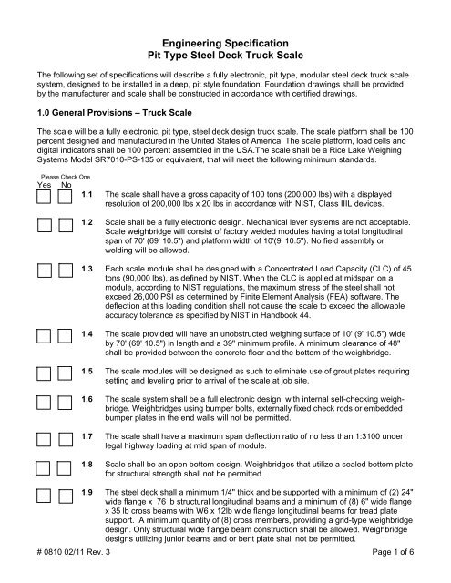
The following set of specifications will describe a fully electronic, pit type, modular steel deck truck scale<br />
system, designed to be installed in a deep, pit style foundation. Foundation drawings shall be provided<br />
by the manufacturer and scale shall be constructed in accordance with certified drawings.<br />
1.0 General Provisions – <strong>Truck</strong> <strong>Scale</strong><br />
The scale will be a fully electronic, pit type, steel deck design truck scale. The scale platform shall be 100<br />
percent designed and manufactured in the United States of America. The scale platform, load cells and<br />
digital indicators shall be 100 percent assembled in the USA.The scale shall be a Rice Lake Weighing<br />
Systems Model SR7010-PS-135 or equivalent, that will meet the following minimum standards.<br />
Please Check One<br />
Yes<br />
No<br />
1.1 The scale shall have a gross capacity of 100 tons (200,000 lbs) with a displayed<br />
resolution of 200,000 lbs x 20 lbs in accordance with NIST, Class IIIL devices.<br />
1.2 <strong>Scale</strong> shall be a fully electronic design. Mechanical lever systems are not acceptable.<br />
<strong>Scale</strong> weighbridge will consist of factory welded modules having a total longitudinal<br />
span of 70' (69' 10.5") and platform width of 10'(9' 10.5"). No field assembly or<br />
welding will be allowed.<br />
1.3 Each scale module shall be designed with a Concentrated Load Capacity (CLC) of 45<br />
tons (90,000 lbs), as defined by NIST. When the CLC is applied at midspan on a<br />
module, according to NIST regulations, the maximum stress of the steel shall not<br />
exceed 26,000 PSI as determined by Finite Element Analysis (FEA) software. The<br />
deflection at this loading condition shall not cause the scale to exceed the allowable<br />
accuracy tolerance as specified by NIST in Handbook 44.<br />
1.4 The scale provided will have an unobstructed weighing surface of 10' (9' 10.5") wide<br />
by 70' (69' 10.5") in length and a 39" minimum profile. A minimum clearance of 48"<br />
shall be provided between the concrete floor and the bottom of the weighbridge.<br />
1.5 The scale modules will be designed as such to eliminate use of grout plates requiring<br />
setting and leveling prior to arrival of the scale at job site.<br />
1.6 The scale system shall be a full electronic design, with internal self-checking weighbridge.<br />
Weighbridges using bumper bolts, externally fixed check rods or embedded<br />
bumper plates in the end walls will not be permitted.<br />
1.7 The scale shall have a maximum span deflection ratio of no less than 1:3100 under<br />
legal highway loading at mid span of module.<br />
1.8 <strong>Scale</strong> shall be an open bottom design. Weighbridges that utilize a sealed bottom plate<br />
for structural strength shall not be permitted.<br />
1.9 The steel deck shall a minimum 1/4" thick and be supported with a minimum of (2) 24"<br />
wide flange x 76 lb structural longitudinal beams and a minimum of (8) 6" wide flange<br />
x 35 lb cross beams with W6 x 12lb wide flange longitudinal beams for tread plate<br />
support. A minimum quantity of (8) cross members, providing a grid-type weighbridge<br />
design. Only structural wide flange beam construction shall be allowed. Weighbridge<br />
designs utilizing junior beams and or bent plate shall not be permitted.<br />
# 0810 02/11 Rev. 3 Page 1 of 6
1.10 <strong>Scale</strong> weighbridge shall be designed to accommodate up to 250 trucks per day for a<br />
period of 25 years without weighbridge fatigue.<br />
1.11 The entire bridge assembly shall be cleaned prior to the addition of any coatings or<br />
paint to the weighbridge modules. Customer reserves the right to inspect the steel<br />
surfaces prior to application of any coatings to the prepared steel surfaces. All steel<br />
surfaces shall be free of all welding gases, residue, oil, mill scale and rust.<br />
1.12 All non-visible steel shall be evenly spray coated with an<br />
asphalt emulsified undercoating.<br />
1.13 All steel elements shall be sandblasted to SSPC-A-SP6 standards.<br />
1.14 All visible steel surfaces will receive a 3-5 mill application of a high solids urethane<br />
primer and a high solids acrylic urethane top coat to a finish of 2-3 mills thickness.<br />
1.15 The scale will be NTEP Certified and shall meet the requirements set forth by the<br />
NIST Handbook 44 for Class IIIL devices. The bidder shall submit a current copy of<br />
Certificate of Conformance (COC) with bid.<br />
1.16 A 1/2" diameter steel rock guard shall be welded to the end modules.<br />
1.18 One Manhole frame and cover 24" square will be provided at each end<br />
of the scale platform.<br />
1.19 Structural steel elements will have a combined minimum weight of 34,700 lbs.<br />
1.20 The scale provided shall be a Rice Lake Weighing Systems SURVIVOR ® Series<br />
Model SR7010-PS-135 or equivalent.<br />
2.0 Load Cells and Junction Boxes<br />
Load Cells are rigidly mounted utilizing a single link suspension to provide equal and consistent and<br />
evenly distributed force to the load cell. Load cells are totally self-contained, and come complete with<br />
mounting stands, single-link suspension, and 60’ of cable to junction box. Compression or rocker style<br />
load cells shall not be permitted.<br />
2.1 Load cells shall be rigidly mounted in fabricated steel stands parallel to traffic flow.<br />
Suspension system will be E4340 material forged single link suspension hardened to<br />
Rockwell “C” 40-45 to allow self-centering and free-floating platform. Rocker column<br />
or compression type load cells requiring check rods, anti-rotation pins or bumper bolts<br />
will not be permitted.<br />
2.2 Load cells will be of the analog type and have a minimum capacity of 75,000 lbs each<br />
with an overload safety factor of 150 percent. <strong>Scale</strong>s utilizing a lower capacity load<br />
cell than 75,000 lbs will not be permitted.<br />
2.3 <strong>Scale</strong>s utilizing proprietary, adjustable bumper bolts or embedded plates in the wall to<br />
minimize movement of the bridge shall not be allowed.<br />
2.4 Systems utilizing internal circuitry to convert analog to digital conversion of the load<br />
cell signal within the load cell shall not be permitted.<br />
# 0810 02/11 Rev. 3 Page 2 of 6
2.5 <strong>Steel</strong> conduit will be provided within the weighbridge for load cell cable runs.<br />
2.6 A flexible screw-type conduit fitting shall be provided at each load cell for protection of<br />
the cable from rats or other rodents. Load cell cable shall be totally enclosed within<br />
permanent conduit provided within the weighbridge. Load cells using connectors of<br />
any type will not be permitted.<br />
2.7 Load cells shall be of 4340 alloy steel nickel plated and shall be scientifically sealed<br />
with a minimum IP67 rating.<br />
2.8 Replacement load cells shall be available from a multitude of vendors nationally, and<br />
shall not be single sourced or of a proprietary design.<br />
2.9 Load cells shall be non-proprietary in design, including both mechanical operation and<br />
electronic transmission of data. Manufacturers using proprietary load cell technology<br />
available from a single source will not be permitted.<br />
2.10 Fiberglass Reinforced Polyester (FRP) junction box with formed contoured edges and<br />
gasketed top access. Junction box shall have a Gore single directional breather<br />
vent with a hydrophobic membrane for pressure equalization. <strong>Steel</strong> junction boxes<br />
shall not be permitted.<br />
2.11 Load cell stands will be flush mounted to concrete piers and anchored using wedge<br />
locks or similar bolts. A maximum of (2) 3/4" x 7" anchor bolts will be required per<br />
stand and will be included in cost of scale. Grout plates or embedded items in the<br />
foundation concrete will not be allowed.<br />
2.12 A 1" braided copper transient bypass cable shall be provided at each load cell from<br />
the weighbridge to the base stand.<br />
2.13 UPS Duplex Voltage regulating transformer, or equivalent.<br />
2.14 UJB-3T6 DC Transient circuitry protection or equivalent.<br />
2.15 Load cells shall be warranted a full five years against failure of all types including<br />
lightning or surge voltage<br />
2.16 A single-point grounding system will be provided. Systems utilizing a multiple point<br />
ground will not be permitted.<br />
3.0 Digital Instrumentation <strong>Specification</strong>s<br />
The scale instrument shall be a Rice Lake Weighing Systems 920i ® Programmable HMI<br />
Indicator/Controller complete with operator friendly diagnostics for the load cells and<br />
digital j-box or equivalent.<br />
3.1 The scale instrument shall be NTEP Certified and meet or exceed all specifications<br />
set forth by NIST, Handbook 44 for Class II, III, and IIIL devices. Additionally the<br />
instrument shall meet or exceed approvals for UL, C-UL and CE. The manufacturer,<br />
on request, shall provide a Certificate of Conformance to these standards.<br />
# 0810 02/11 Rev. 3 Page 3 of 6
3.2 The scale instrument shall be housed in an all stainless steel, NEMA 4X/IP66<br />
enclosure measuring 10.5" wide x 11.5" high x 4.5" deep with swing-away mounting<br />
base for ease of installation.<br />
3.3 The instrument shall be 100 percent manufactured by the manufacturer<br />
of the weighbridge assembly.<br />
3.4 The instrument shall be microprocessor based.<br />
3.5 The scale instrument shall be fully programmable and configurable according to the<br />
needs of the application. Custom programming for the application will be available<br />
through common programming techniques.<br />
3.6 The scale display shall be a backlit LCD graphical display with minimum size of 3.4"<br />
high x 4.6" wide with characters from 1/4" to 1.2" high. Display must be capable of<br />
displaying alpha and numeric characters or graphic images.<br />
3.7 The instrument shall allow hook up of a QWERTY-type, computer-style keyboard.<br />
3.8 The front panel of the instrument shall have the following operational keys as<br />
standard with tactile feedback:<br />
• Zero<br />
• Print<br />
• Gross/Net • Clear<br />
• Tare<br />
• Decimal Point<br />
• Units • Numeric 0-9<br />
3.9 The instrument shall have the following custom Soft Keys - 5-User<br />
Defined Function Keys:<br />
• Driver Number<br />
• Contract Number<br />
• Weigh In<br />
• Weigh Out<br />
3.10 The instrument shall have the following displayed operational annunciators:<br />
• Gross, Tare, Net, Zero, Motion<br />
• Three units of measurement<br />
3.11 The scale instrument shall have the capability of powering up to 16 - 350<br />
Ohm load cells.<br />
3.12 The instrument shall have the ability to display both gross and net weights and<br />
the ability to recall gross or tare weights in the net mode.<br />
3.13 The instrument shall have the ability to provide in/out, gross/tare/net calculation of<br />
individual truck weights and storage for the following information<br />
• 1,000 open transactions<br />
• 1,000 tare weights<br />
• Data base report<br />
# 0810 02/11 Rev. 3 Page 4 of 6
3.14 The instrument shall have a minimum of four standard bidirectional serial ports with<br />
the following configurations available:<br />
Com. 1 – RS-232<br />
Com. 2 – RS-232<br />
Com. 3 – RS-232, 20mA current loop<br />
Com. 4 – RS-232, 20mA current loop<br />
3.15 Set Points<br />
Four digital I/O ports on board.<br />
3.16 The scale instrument shall be designed to provide noise protection for<br />
RFI, EMI and ESD.<br />
3.17 The excitation voltage shall be 10 VDC.<br />
3.18 The instrument shall have an automatic zero tracking feature that will be<br />
programmable and in compliance with NIST, Measurement Canada<br />
and OIML regulations.<br />
3.19 The instrument shall be fully configurable through the front panel of the instrument.<br />
3.20 The instrument shall include as standard surge voltage protection as recommended<br />
by the manufacturer.<br />
3.21 The digital instrument shall be warranted by the manufacturer for two years<br />
from date of installation.<br />
3.22 The instrument shall have a multi-level digital filtering system for environmental<br />
noise or vibration.<br />
3.23 Individual load cell monitoring and system diagnostics when paired with<br />
iQUBE 2® junction box.<br />
3.24 The scale instrument shall have an internal resolution of 8,000,000 counts.<br />
3.25 Operating temperature for the instrument shall be 14F to 104F (-10C to 40C).<br />
3.26 <strong>Scale</strong> instrument shall have the ability to be panel mounted.<br />
3.27 Customized programmable print formats including 20 auxiliary print formats.<br />
3.28 Operational power input shall be 115 or 230 VAC, ±10 percent @ 3.15 Amp<br />
maximum. 50/60 Hz single phase.<br />
3.29 The scale instrument shall have the capability of receiving custom programs with up<br />
to 256 display widgets and 10 screens.<br />
# 0810 02/11 Rev. 3 Page 5 of 6
3.30 The instrument shall have a real time clock and battery backed feature.<br />
3.31 A/D conversion rate shall be updated at 120 times per second minimum.<br />
3.32 Multi-range/internal selection for setting two or three weight ranges with different<br />
display division sizes.<br />
# 0810 02/11 Rev. 3 Page 6 of 6


